Induction heating of the filling conveyor molds

Author: Timofeev Viktor N., Strombskoy Ilya A., Alekseeva Anna B.
Journal: Журнал Сибирского федерального университета. Серия: Техника и технологии @technologies-sfu
Article in issue: 5 т.14, 2021.
Free access
In the smelting and foundry production of aluminum ingots, filling conveyors are widely used. Aluminum ingots of a certain shape and weight are obtained by crystallizing liquid aluminum (melt) in the molds of the filling conveyor. As the mills move along the conveyor, the melt gradually hardens in them. In high-performance conveyors, the mills move through the water to increase the cooling rate of the melt. Therefore, after the mill is freed from the hardened ingot, water enters it. In order to avoid temperature shock and possible release of liquid metal, the molds must be dried and heated before pouring. At present, gas burners are used in aluminum plants for this purpose [1]. The purpose of this work is to study the possibility of induction heating of the filling conveyor molds.The calculation is carried out using Fourier series in complex form and approximate boundary conditions on the surface of ferromagnetic molds. The approximate boundary conditions avoid the need to calculate the electromagnetic field in a nonlinear ferromagnetic medium.In the heated object, the energy of the induced alternating electric field is irreversibly converted into thermal energy. This dissipation of thermal energy, which leads to the heating of the object, is determined by the presence of conduction currents (eddy currents).Induction heating is widely used in metallurgy for melting, heating and mixing of electrically conductive bodies. The method is based on the absorption of electromagnetic energy by bodies of an alternating magnetic field created by an inductor. The heated product is located in the immediate vicinity of the inductor. There are many publications on analytical and numerical, analysis of physical processes in the inductor-heated billet system. In this paper, an analytical calculation of electromagnetic processes in the system of inductor - ferromagnetic molds of the filling conveyor is carried out. The analytical solution is obtained by using the approximate boundary condition of L. R. Neumann on the surface of nonlinear ferromagnetic molds.
Filling conveyor, induction heating, inductor - mold system, aluminum ingot, magnetic field
Short address: https://sciup.org/146282317
IDR: 146282317 | UDC: 621.365.5 | DOI: 10.17516/1999-494X-0335
Индукционный нагрев изложниц разливочного конвейера
В плавильно-литейном производстве алюминиевой чушки широко используются разливочные конвейеры. Алюминиевая чушка определенной формы и веса получается путем кристаллизации жидкого алюминия (расплава) в изложницах разливочного конвейера. По мере движения изложниц по конвейеру расплав в них постепенно затвердевает. В высокопроизводительных конвейерах для увеличения скорости охлаждения расплава изложницы двигаются по воде. Поэтому после освобождения изложницы от затвердевшей чушки в нее попадает вода. С целью исключения температурного шока и возможного выброса жидкого металла изложницы необходимо перед заливкой просушить и подогреть. В настоящее время на алюминиевых заводах для этого используют газовые горелки [1]. Целью данной работы является исследование возможности индукционного нагрева изложниц разливочного конвейера.Расчет осуществляется с использованием рядов Фурье в комплексной форме и приближенными граничными условиями на поверхности ферромагнитных изложниц. Приближенные граничные условия позволяют избежать необходимости расчета электромагнитного поля в нелинейной ферромагнитной среде.В нагреваемом объекте энергия индуцированного переменного электрического поля необратимо превращается в тепловую энергию. Эта диссипация тепловой энергии, приводящая к нагреву объекта, определяется наличием токов проводимости (вихревых токов).Индукционный нагрев широко применяется в металлурги для плавления, нагрева и перемешивания электропроводящих тел. Метод основан на поглощении телами электромагнитной энергии переменного магнитного поля, создаваемого индуктором. Нагреваемое изделие располагается в непосредственной близости от индуктора. Существует много публикаций по аналитическому и численному анализу физических процессов в системе индуктор - нагреваемая заготовка. В данной работе проведен аналитический расчет электромагнитных процессов в системе индуктор - ферромагнитные изложницы разливочного конвейера. Аналитическое решение получено благодаря использованию приближенного граничного условия Л. Р. Неймана на поверхности нелинейных ферромагнитных изложниц.
Text of the scientific article Induction heating of the filling conveyor molds
The structure and the principle of operation of the filling conveyor with induction heating of the molds is described
Figure 1 schematically shows the filling conveyor for the production of aluminum ingots. Here, 1 is a filling wheel; 2 is a mold; 3 is a water-cooling system; 4 is a solid ingot; 5 is a gas burner; 6 is an inductor of an alternating magnetic field.
The device works as follows. From the filling wheel 1, the melt enters the mold 2, which moves from point A to point B. Along the way, the metal mill passes through a water-cooling system. The melt in the molds crystallizes and at point B the solid ingot 4 falls out of the mold and is placed in a bag for transportation. Gas burners 5 can be used to dry and heat the molds before pouring the melt at point A. In this paper, we will consider the possibility of using an induction heating system for molds. The variable magnetic field inductor 6 is installed at the bottom of the conveyor. The inductor 6 consists of a magnetic circuit 7 and a winding 8 laid in the grooves of the magnetic circuit. When the winding 8 is connected to an alternating voltage source, an electric current occurs in it, creating an alternating magnetic field. According to the law of electromagnetic induction, an alternating magnetic field induces eddy currents in steel mills, the energy of which leads to an increase in the temperature of the molds.
To increase the temperature of the mill by a value of Δ T 21 = T 2 – T 1 , an amount of energy (1) is required.
θ 21 = mC p Δ T 21 , (1)
where m – the weight of the mold, kg;
Cp – specific heat capacity, J/kg * K;
T 1 – the temperature of the mold at the point G (before entering the inductor zone), K;
T 2 – the temperature of the mold at point D (at the exit from the inductor zone), K.
The active power P entering the mold from the inductor must ensure that the energy balance is maintained
Pt 1 = θ 21 + Δ P p t 2 , (2)
where t 1 – the time of movement of the mold in the zone of the inductor, sec; t 2 – the time of the mold movement from the inductor to the melt filling, sec;
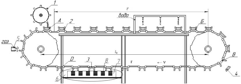
Fig. 1. Schematic drawing of the filling conveyor
Δ Pp – the power of energy dissipation when cooling the mold, when moving from the inductor zone to the metal casting point (point A), WA.
Computational and mathematical models of the inductor-mill system
When constructing the computational model, we consider the following assumptions [2]:
-
1. We present the molds as a homogeneous ferromagnetic medium with a specific electrical conductivity of γ c and a magnetic permeability of μ a , as a function of the magnetic field strength of μ a = μ 0 ∙ μ c = f ( H ). The homogeneous medium moves comparative to the inductor at a constant speed υ.
-
2. The magnetic core of the inductor is represented by a smooth medium with a specific electrical conductivity of γ c = 0, and a magnetic permeability of μ c = ∞, the grooves with the winding conductors are conditionally accepted as surface currents with a linear density, A / m.
j _ j^i^t-ax) , (3)
where ω0 = ωs; ω – angular frequency, C ; s – slip; α = π / τ.
(4, 5)
The dimensions of the device in the transverse direction (y-axis) are assumed to be infinitely large. The coordinate system is considered to be rigidly connected to the ferromagnetic medium.
The calculation model that meets the accepted conditions is shown in Figure 2.
z A
) Po;v
T и
6'
////////////////////////////////к
Ho; y=o
L 2pr , I
T7777777777777T777777777777777777777V.
ц=о° j
Y=o
Fig. 2. Calculation model of the system of inductor-ferromagnetic molds
The vectors of the electric and magnetic field strengths have component values
E(/,x,z) = ey -Ey; H(t,x, -) = exHx (t,x,z) +ezHz (t,x,z) . (6, 7)
It is advisable to solve the problem of calculating the electromagnetic field through the complex component of the electric field strength E^x.z^ , which can be represented in accordance with (3).
E^x.z^E/z^"
The mathematical model for determining Ey(-) , in accordance with the calculation model, has the form:
The Laplace equation
.
Boundary conditions
Ях(0) = 7;^(5) = (1 + /0,6).
“^ й ^ ,
Yc
(10, 11)
where μ c ( H ) is the value of the magnetic permeability on the surface of the ferromagnetic medium, determined from the universal magnetization curve by the effective value of the magnetic field strength H 0 [3]. Due to the pronounced surface effect H 0 ≈ Hx . Expression 11 is an approximate boundary condition of L. R. Neumann [4].
From Maxwell's equation rotE = -ico^H , we get
Considering (12), the boundary conditions (10) and (11) are transformed to the form
--^0> = /о)ц07; ЕД5) = -^ Ц5), dz ’ 5 =
(13, 14)
where
.
ModtoN Yc
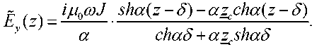
The presented mathematical model (9–15) allows us to obtain an expression for the electric field strength in the form:
In accordance with (12), we write the expression for the component of the magnetic field strength
~ сИа^-б^-ауИа^-б^)
Hx (^) = 7-- cha6 + azsha6
.
We introduce a dimensionless coefficientf
л цс (Я)
T^Vro^ Yc
In this case, in accordance with (15), we have
α z c = –0,6ζ + iζ .
On the surface of ferromagnetic molds z = δ, the expression (17) takes the form
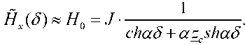
From here we get
J = H 0 ∙ | chαδ + (–0,6ζ + iζ ) shαδ |.
Equation (21) is non-linear, since the quantity ζ included in 1 depends on

For a wide class of steels, the dependence

= /(Я0) is presented in Table 1 [2].
The third row of Table 1 shows the values of the relative coefficient ζ, calculated by (18), for the following values: ω = 2πf = 314 ∙ c -1; τ = 0,2 m; μ 0 = 4π ∙ 10–7 Gn/m. The fourth line shows the value of the current density J , determined by (21).
For a given value of the linear current load J , we determine the value H 0 from Table 1 and find the value — .
Table 1. Basic parameters
|
H 0 ∙ 102, A/m |
|
|
ЬМ4(ь, \ у m Ch сч Ch m h- ,—। oo Om·сек-1 |
о |
|
оо^-с^^^г^^-оочо m Г n P О г-н сп ^ сп мь т сч ^ г^ ^ ^ сч ζ, о. е. 1 ^^ i-1 СЧ ^O x] 1 1 1 *^h i—i O^ b^ 1 1 V*) V V rn r/ r/ r/ ^ ^ ^ o' o' o' o' |
o' |
|
J ∙ 102, A/m S г^^^с^сп^-чо^^с^^-^^ |
Electromagnetic power of the inductor
The complex electromagnetic power transmitted by the inductor to the gap is equal to
8ЭМ =-bL-Ev^y J , (22)
where, l and L are the width and length of the inductor, m; J is the conjugate complex of the current density.
From (16) we write где
5/0) =
. n0coJn shad + z^achad a chad + zashad
Substituting (23) in (22), we write the expression for the electromagnetic power
8™ = рЭМ + ^эм = IL№t .J2^x + i к
, shad + z achad
(JT + /У) = I -------— .
chad + z a shad
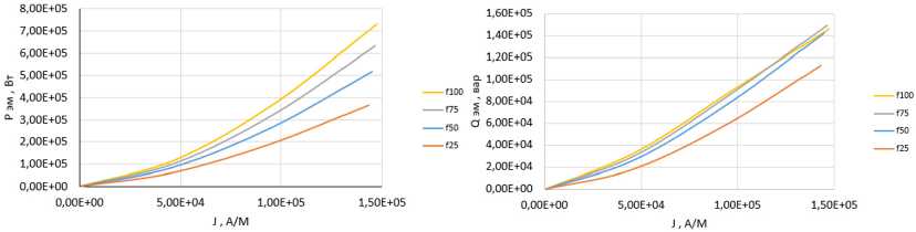
Fig. 3. Dependence of active and reactive power on frequency
Here, the active and reactive electromagnetic power.
P ЭМ = Re{ S ЭМ} и Q ЭМ = Im{ S ЭМ}. (26,27)
Fig. 3 shows the dependences of the active P ЭМ and reactive Q ЭМ powers on the linear current density, at different frequencies of f , Hz.
Conclusions
-
1) On the basis of the accepted assumptions, a mathematical model is constructed for determining the vectors of the electromagnetic field, in which the nonlinear properties of the ferromagnetic medium are considered by using the approximate boundary condition of L. R. Neumann.
-
2) The dependences between the magnetic field strength and the corresponding magnetic permeability value on the linear current density of the inductor at different values of parameter ζ are obtained, all values are given in Table 1.
-
3) At the required value of the active power providing the set temperature of the mold at the melt supply point, the value of the linear current load of the inductor is determined and all the electromagnetic characteristics of the inductor – mold system are calculated.
References Induction heating of the filling conveyor molds
- Patent of the Russian Federation No. 2014146976/02, 2014.11.21. Complex for pouring liquid metal into molds on a conveyor // RU2 578 272 C1 / Trusov Vladimir Alexandrovich
- Voldek A. I. Electric machines: Textbook for electrical engineering. spec. vuzov. Leningrad: Energy, 1974. 839 p.
- Maergoiz I. D. Calculation of the surface effect in ferromagnetic bodies covered with a conducting layer. Electricity, 1970, 2, 83-86 p.
- Neiman L. R. Surface effect in ferromagnetic bodies. M.: Gosenergoizdat, 1949. 190 p.
