Influence of hydrodynamic regimes of oil and gas mixtures on the efficiency of heat exchange

Author: Salimov Zakirzhan Salimovich, Ismailov Oibek Yulibaevich, Saydahmedov Shamshidinhuzha Muhtarovich, Zaikov Gennadiy Efremovich
Journal: НБИ технологии @nbi-technologies
Section: Технико-технологические инновации
Article in issue: 1 (16), 2015.
Free access
The results of experimental studies identify the degree of intensification of the processes of oil and gas mixtures heating in horizontal pipe due to changes in hydrodynamic regimes. So, at oil and gas mixtures heating processes it is desirable to consider their implementation in a turbulent flow, which will help to develop energy-saving technology of thermal preparation of hydrocarbons to the primary distillation in refineries by optimizing the hydrodynamic conditions in tubular heat exchangers.
Physical and chemical properties of oil and gas mixture, similarity criteria, calorific efficiency, heat transfer coefficient, the amount of transferred heat, degree of process intensification, heat exchange efficiency
Short address: https://sciup.org/14968378
IDR: 14968378 | UDC: 665.7:66 | DOI: 10.15688/jvolsu10.2015.1.4
Влияние гидродинамических режимов нефтяных и газовых смесей на эффективность теплообмена
В работе приведены результаты экспериментальных исследований для определения степени интенсификации процессов нефтяных и газовых смесей в горизонтальной трубе отопления вследствие изменения гидродинамических режимов. Показано, что для развития энергосберегающих технологий при термической подготовке углеводородного сырья к первичной обработке целесообразно учитывать турбулентность нефтяных и газовых смесей.
Text of the scientific article Influence of hydrodynamic regimes of oil and gas mixtures on the efficiency of heat exchange
DOI:
The problem of rational and efficient use of energy resources is one of the most important. With increasing of energy capacity and output more and more weight and dimensions of heat exchangers use are increasing. For their operation a huge amount of electricity and heat is in use. Improving the efficiency of heat transfer and reducing the weight and dimensions of these devices depends on the rational organization in their hydrodynamic regimes of heat exchanging traffic flows. Horizontal pipe and tubular devices are characterized with the fact that they can organize any hydrodynamic regimes of flow: laminar ( Re < 2 300), transitional (2 300 < Re < 10 000) and turbulent ( Re > 10 000), which differ with varying intensity of hydro, thermal and mass transfer processes [6].
At refineries of the Uzbekistan a hydrocarbon feedstock oil-gas mixture is used. The share of gas condensate in the mixture varies in the redistribution of 20 to 80 %.
Objects and methods
To study the heating of hydrocarbons (oil, gas condensate, and mixtures thereof) with vapors of gas condensate and to establish the influence of operating parameters of the efficiency of heat transfer in tubular heat exchangers, we collected the experimental setup the concept of which is shown at Fig. 1. The experimental setup consists of steam generator 15, the heat exchanger of the “tube in tube” with pipes 8 and 9 are mounted on the supporting stands 16, meters for metering gas 13 and hydrocarbon feed 4, the centrifugal pump 2 for pumping the raw material, expenditure feedstock tank 1 and the dipstick 11 collecting the heated feed. The unit is equipped with valves 3 and 12 to control the flow of natural gas and hydrocarbon mercury thermometers 5 and 7 for measuring the temperature of the raw material in the inner tube and the heating medium in the annulus apparatus and gauges 6 for measuring the differential pressure of heating medium in the end portions of the heat exchanger. The heat transfer tube 9 has an inner diameter of 20 mm and effective length 2 000 mm. The housing unit 8 is made of pipes with an inner diameter of 50 mm [4].
To the surface of the inner tube with pitch size 500 mm five pockets with outer sleeve are welded, into which in an oil bath thermometers are laid for temperature measurement control
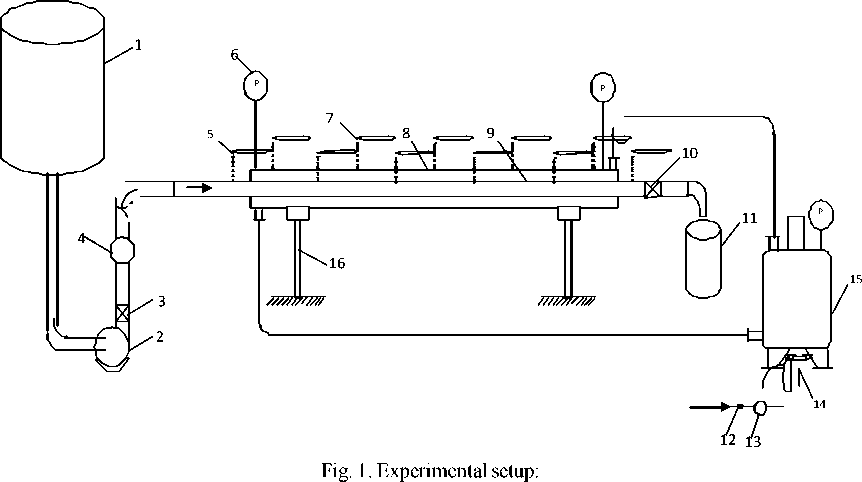
1 – the storage container for hydrocarbon raw materials; 2 – centrifugal pump; 3 , 10 and 12 – valve;
4 – counter flow of raw materials; 5 – thermometers for raw materials; 6 – pressure gauges;
7 – thermometers for heating agent; 8 – outer pipe (casing); 9 – inner tube; 11 – dimensional container heated raw materials;
13 – gas flow meter; 14 – burner gas; 15 – steam generator; 16 – support column
of hydrocarbon feedstock flowing through it. A cylindrical gap formed between the pocket layer and the liner is filled with insulating material. Such an arrangement allows the pocket to minimize the influence of temperature heating medium that is streamlined sleeve for temperature measurement accuracy of the hydrocarbon feedstock in the inner tube in the experiments. To the outer tube with 400 mm step six pockets are welded with oil for bookmark thermometers that measure the temperature of the heating agent in the annulus of the machine. To prevent heat losses to the environment the entire outer surface of the pilot plant and the steam generator is coated with glass wool and sealed with aluminum foil.
In experiments gas condensate vapors were used as a coolant, basic parameters of which are given in Table 1. The experiments were performed at a rate of hydrocarbon feedstock in the inner pipe 0.1061; 0.2123; 0.3184; 0.4246; 0.5307; 0.6369; 0.7431 and 0.8492 m/s. The process was organized in countercurrent movement of heat exchanging flows. The limits of speed variation of hydrocarbons provide the establishment of various hydrodynamic modes of their motion in the experimental apparatus.
Using the results of the experiments, the basic physical, chemical and thermal properties of the investigated materials and coolant were studied and then the heat transfer coefficients of the heating medium to the outer wall of the inner tube and a 1 from the inner wall of the pipe to the heated feedstock a 2 along the length L of the device were calculated.
The criterion equation to calculate the heat transfer coefficient a 1 is selected on the basis on the value of the Reynolds number Re [2; 3]:
R e = u ( D in - d ex ) p / Ц , (1)
where u = 4 V / p ( D 2 in - d 2 ex ) - average speed of heating medium (steam condensate) in the annulus system, m/
s; V – volumetric flow rate, m3/s; Din – inner diameter of the housing unit, m; dex – the outer diameter of the inner tube, m; p and m - respectively, the density (kg / m3) and dynamic viscosity ( Pa . s ) of coolant.
Re meaningfully turbulent motion of vapor condensate in the annulus experienced exchanger was set, as the Reynolds number is in the redistribution of 147.683 + 162.985 (see Table 25). In this case, the criterion equation to determine the Nusselt number is:
Nu = 0023 • Re 08 • Pr 0 . 4 •

where Pr = ( S m ) / l - Prandtl number; C and l, respectively – specific heat (kJ / kg) and the coefficient of thermal conductivity (W/m . K) of the coolant.
According to the calculated values of the criteria Nu heat transfer coefficient a 1 from the heating medium to the outer wall of the heat exchange tube was determined [6]:
Nu • x « 1 = ——, d eq
where deq – equivalent diameter of the annulus section of the apparatus; deq = din – dex = 0.025 m.
Values of the coefficient of heat transfer from the inner wall of the pipe unit to a heated environment, a 2 are determined depending on the mode of flow in a horizontal pipe.
The value of the Reynolds number, which determines the modes of movement of hydrocarbons in a horizontal pipe system, was determined by the well-known formula Re/, = -in—ex" - where u - speed test liquid, m/s; n n - thVkmematic W, ™2/s.
To calculate the Nusselt number in laminar flow in a horizontal pipe the following criterion equation was used [2]:
Table 1
The main parameters of gas condensate
|
Heating agent |
Pressure, P , kPa |
Temperature, t , 0С |
Velocity, to , m/s |
Density at 20 0С temperature, p , kg/m3 |
Kinematic viscosity at 20 0C temperature, v , 10-6 m2/sec |
|
Vapors of gas condensate |
250 |
120 |
6.8 |
759 |
1.03 |
0,25
I } ,
Nu . = 0,17 Re”"IV Gr- —I • e t ,
V wa J
An approximate calculation of the criterion Nuli when forced movement of the fluid flow in the pipe in the transition mode is performed by the following equation:
Nu i = 0,008 Re” -9 Pr^^. (5)
Criterion equation of heat transfer for turbulent movement of oil in double-tube apparatus is as follows:
Nu i = 0,021 Re” - 8 Pr”-43
0,25 ,
r
-
l L- I
Г) ^ t ,
Pr )
wa J
where Nu i =din -a 2 / 1 - is a Nusselt number characterizing the similarity of heat transfer processes at the interface between the wall and the flow of the sample liquid; Prli = C ■ v - p / 1 - is a Prandtl number at an average temperature of fluid flow; Gr i = g - d3 / v - is a Grashof criterion at an average temperature of fluid flow; Pr wa = C ■ v ■ p / 1 - is a Prandtl number at the average temperature of the pipe wall; e t = fL / d ) - is a coefficient taking into account the effect of the size of the heat exchange tube to increase the heat transfer coefficient a2 .
Coefficient of heat transfer from the wall to the liquid heat exchange tube a 2 is calculated from the following expression:
α2
Nu li • X
The value of heat transfer coefficient K for 1 m length of experienced heat exchanger was defined by the equation set out in the source [3]:
— + — +12 , 3 Ig ^ + — + (8)
α r α r λ r r r
-
1 ex 2 in in pol ex pol in
where rex и rin – are outer and inner radius of inner tube, m; rpol ex and rpol in – are external and internal thermal conductivity of contamination of the inner tube, W/(m2K).
To determine the amount of heat transferred from the coolant to heated liquid the basic heat transfer equation was used:
Q = KL ^ t av , (9)
where K is the heat transfer coefficient, W/(m2K); A tav - the average temperature difference, °C; L -length of horizontal pipe, m.
The degree of intensification (or increasing of the efficiency of heat exchange) with heating of oil and gas mixtures by changing the hydrodynamic regime is determined from the following relations:
i = a£= K L . = QL a a 2’ К K'. q Q',
where i a iK and i q - are the degree of intensification of heat transfer and heat transfer coefficients K, increasing the amount of heat transferred Q due to changes in hydrodynamic regimes; a ' 2, K ’ и Q - accordingly, are heat transfer, heat transfer and the quantity of heat transferred in a laminar flow regime coefficients; a ’ 2 , K '' and Q'' – values of factors transfer and heat transfers, and also quantity of transferable heat – with transitional and turbulent motion of oil and gas mixtures in a horizontal pipe.
Results and discussion
The results of studies on determination of the degree of influence of hydrodynamic conditions on the efficiency of heat irradiation and heat transfer coefficients as well as the amount of heat transferred at oil and gas flow moving in a horizontal pipe were summarized and presented in Tables 2-5.
The data in Table 2 indicate that the regimes of the oil in the inner tube of a double-tube heat exchanger do smoothly transit from laminar (at u ex = 0.1061 x 0.4246 m/s) to the transition mode ( u ex > 0.5307 m/s). However, under the conditions of the experiment the turbulent regime was not formed. In laminar flow heat transfer coefficient of the wall to the heated oil a 2 increases from 420 to 681 W/(m2K), the coefficient of heat transfer K increases from 7.3 to 10.9 W/(m2K), and the amount of transferred heat Q varies in the redistribution of 8.7 to 219 watts. In the transient mode the coefficient of heat transfer from a wall to the heated oil a 2 increases from 681 to 1011 W/ (m2K), the coefficient of heat transfer – from 10.9 to 14.9 W/(m2K), and the amount of transferred heat varies at the redistribution of 219.5 to 1 162.9 watts.
Table 2
|
Heat transfer agent (vapors of gas condensate) |
Heated medium (oil) |
Performance of heat transfer |
|||||||||||
|
Change in the temperature of heat carrier, 0С |
Re |
Nu |
α 1 , W/m2K |
Rate of hydrocarbons raw materials, w , m/s |
Change in the temperature of heat carrier, 0С |
Re |
Nu |
α 1 , W/m2K |
K , W/m2K |
Δ t av , 0С |
Q, W |
||
|
t н |
t к |
t н |
t к |
||||||||||
|
120 |
76 |
165138 |
4122 |
3495 |
0.1061 |
20 |
66 |
615 |
66.23 |
420 |
7.3 |
0.6 |
8.69 |
|
120 |
72 |
163872 |
4073 |
3457 |
0.2123 |
20 |
63 |
1136 |
84.1 |
516 |
8.7 |
1.2 |
20.96 |
|
120 |
71 |
163241 |
4029 |
3447 |
0.3184 |
20 |
61 |
1826 |
94.2 |
587 |
9.7 |
4.7 |
91.45 |
|
120 |
67 |
162581 |
4012 |
3428 |
0.4246 |
20 |
56 |
2021 |
102.4 |
681 |
10.9 |
10 |
219.5 |
|
120 |
63 |
196257 |
3975 |
3386 |
0.5307 |
20 |
50 |
2326 |
125.4 |
762 |
11.9 |
15.8 |
378.7 |
|
120 |
58 |
158364 |
3962 |
3378 |
0.6369 |
20 |
42 |
2456 |
142.7 |
976 |
14.4 |
23.4 |
677.5 |
|
120 |
54 |
156435 |
3921 |
3354 |
0.7431 |
20 |
34 |
2531 |
153.8 |
1012 |
14.8 |
30.5 |
905.9 |
|
120 |
50 |
156421 |
3892 |
3298 |
0.8492 |
20 |
23 |
2623 |
146.2 |
1011 |
14.9 |
39.3 |
1162.9 |
Table 3
|
Heat transfer agent (vapors of gas condensate) |
Heated medium (oil) |
Performance of heat transfer |
|||||||||||
|
Change in the temperature of heat carrier, 0С |
Re |
Nu |
α 1 , W/m2K |
Rate of hydrocarbons raw materials, w , m/s |
Change in the temperature of heat carrier, 0С |
Re |
Nu |
α 1 , W/m2K |
K , W/m2K |
Δ t av , 0С |
Q , W |
||
|
t н |
t к |
t н |
t к |
||||||||||
|
120 |
57 |
157354 |
3921 |
3335 |
0.1061 |
20 |
82 |
3412 |
69.52 |
475 |
8.1 |
1.75 |
28.4 |
|
120 |
53 |
155231 |
3901 |
3321 |
0.2123 |
20 |
80 |
6913 |
136.8 |
889 |
13.5 |
2.93 |
79.1 |
|
120 |
49 |
152123 |
3756 |
3301 |
0.3184 |
20 |
77 |
9152 |
161.2 |
1349 |
18.1 |
8.21 |
297.2 |
|
120 |
45 |
152872 |
3834 |
3127 |
0.4246 |
20 |
72 |
12894 |
279.3 |
1958 |
22.5 |
13.5 |
607.5 |
|
120 |
41 |
151293 |
3885 |
3246 |
0.5307 |
20 |
66 |
14589 |
326.8 |
2258 |
24.7 |
19.3 |
953.4 |
|
120 |
36 |
150251 |
3812 |
3241 |
0.6369 |
20 |
58 |
16492 |
365.2 |
2654 |
26.9 |
26.9 |
1447.2 |
|
120 |
32 |
143284 |
3735 |
3184 |
0.7431 |
20 |
50 |
17294 |
397.5 |
2816 |
27.5 |
34.0 |
1870 |
|
120 |
28 |
147683 |
3725.3 |
3112 |
0.8492 |
20 |
39 |
18657 |
439.6 |
3087 |
28.5 |
42.8 |
2439.6 |
Table 4
Improving the efficiency of heat transfer by heating a mixture of oil and gas condensate consisting of 20 % oil and 80 % gas condensate, due to changes in hydrodynamic regimes
|
Heat transfer agent (vapors of gas condensate) |
Heated medium (oil) |
Performance of heat transfer |
|||||||||||
|
Change in the temperature of heat carrier, 0С |
Re |
Nu |
α 1 , W/m2K |
Rate of hydrocarbons raw materials, w , m/s |
Change in the temperature of heat carrier, 0С |
Re |
Nu |
α 1 , W/m2K |
K , W/m2K |
Δ t av , 0С |
Q , W |
||
|
t н |
t к |
t н |
t к |
||||||||||
|
120 |
63 |
159267 |
3980 |
3383 |
0.1061 |
20 |
77 |
2750 |
63.05 |
431 |
7.5 |
1.75 |
26.2 |
|
120 |
59 |
157814 |
3950 |
3357 |
0.2123 |
20 |
75 |
5600 |
118.7 |
811 |
12.5 |
2.34 |
58.5 |
|
120 |
55 |
156382 |
3919 |
3331 |
0.3184 |
20 |
72 |
8032 |
167.1 |
1144 |
16.2 |
7.62 |
246.8 |
|
120 |
51 |
154968 |
3890 |
3306 |
0.4246 |
20 |
67 |
10240 |
256.4 |
1757 |
21.5 |
12.9 |
554.7 |
|
120 |
47 |
153575 |
3860 |
3281 |
0.5307 |
20 |
61 |
12129 |
301.0 |
2066 |
23.6 |
18.7 |
882.6 |
|
120 |
44 |
152542 |
3838 |
3262 |
0.6369 |
20 |
51 |
13306 |
340.3 |
2343 |
25.2 |
26.4 |
1330.6 |
|
120 |
38 |
150510 |
3794 |
3226 |
0.7431 |
20 |
45 |
14710 |
376.5 |
2596 |
26.5 |
33.4 |
1770.2 |
|
120 |
34 |
149180 |
3766.3 |
3201 |
0.8492 |
20 |
34 |
15231 |
407.8 |
2821 |
27.6 |
42.3 |
2334.9 |
Table 5
Improving the efficiency of heat transfer by heating a mixture of oil and gas condensate consisting of 40 % oil and 60 % gas condensate, due to changes in hydrodynamic regimes
The data in Table 3 shows that the regimes of gas condensate movement in the inner tube of a double-tube apparatus smoothly transit from the transitional regime (at u ex = 0.1061 + 0.3184 m/s) to turbulent (at u ex > 0.4246 m/s). In the transient mode the coefficient of heat transfer from a wall to the heated oil a 2 increases from 475 to 1349 W/(m2K), the coefficient of heat transfer K – from 8.1 to 18.1 W/(m2K), and the amount of transferred heat Q changes in the redistribution of 28.4 to 297.2 watts. At a turbulent flow the coefficient of heat irradiation from the wall to the heated oil a 2 increases from 1 958 to 3 087 W/(m2K), the coefficient of heat transfer – from 13.5 to 42.8 W/(m2K), and the amount of transferred heat varies within the redistribution of 607.5 to 2 439.6 watts (Table 4).
At heating of oil and gas condensate mixture (20 % oil + 80 % gas) in a horizontal pipe, the driving modes seamlessly move from transitional (with u ex = 0.1061 + 0.3184 m/s) to turbulent (at u ex > 0.4246 m/s). In the transient mode the coefficient of heat irradiation from the heated wall to the sample liquid a 2 increases from 431 up to 1.144 W/(m2K), the coefficient of heat transfer K – from 7.5 to 16.2 W/(m2K), and the quantity of heat transferred Q changes in the redistribution of 26.2 to 246.8 watts. At a turbulent flow the coefficient of heat irradiation from the heated wall to fluid a 2 does increase
from 1 757 to 2 821 W/(m2K), the coefficient of heat transfer – from 21.5 to 27.6 W/(m2K), and the amount of transferred heat varies within the range of 554.7 to 2 334.9 watts.
The data in Table 5 shows that the regimes of hydrocarbon feedstock (a mixture of oil and gas condensate 40 % oil + 60 % gas) in the inner tube of a double-tube unit smoothly transit from moving (at u ex = 0.1061 m/s) to the turbulent regime (when u ex > 0.2123 m/s). In the transient mode the coefficient of heat irradiation from the heated wall to the sample liquid a 2 is 481 W/(m2K), the coefficient of heat transfer K – 8.2 W/(m2K), and the amount of transferred heat Q has reached 19.2 W. In the turbulent flow the heat irradiation coefficient from the heated wall to the feedstock a 2 increases from 704 to 2 553 W/(m2K), the coefficient of heat transfer – from 11.2 to 26.3 W/(m2K), and the amount of transferred heat varies in a range of 52.4-2 224.9 watts.
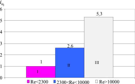
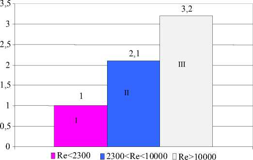
From the analysis of the experimental data presented in Tables 2-5, it follows that the efficiency of heat transfer by heating the oil-gas condensate mixtures depends on their flow regimes. For example, improved efficiency of heat transfer of oil and gas condensate by heating a mixture consisting of 40 % oil and 60 % of gas condensate (i.e., increasing of a 2 K, Q values) due to changes in hydrodynamic conditions are illustrated in the diagrams (see Fig. 2-4).
|
Heat transfer agent (vapors of gas condensate) |
Heated medium (oil) |
Performance of heat transfer |
|||||||||||
|
Change in the temperature of heat carrier, 0С |
Re |
Nu |
α 1 , W/m2K |
Rate of hydrocarbons raw materials, w, m/s |
Change in the temperature of heat carrier, 0С |
Re |
Nu |
α 1 , W/m2K |
K , W/m2K |
Δ t av , 0С |
Q , W |
||
|
t н |
t к |
t н |
t к |
||||||||||
|
120 |
63 |
159267 |
3980 |
3383 |
0.1061 |
20 |
77 |
2750 |
63.05 |
431 |
7.5 |
1.75 |
26.2 |
|
120 |
59 |
157814 |
3950 |
3357 |
0.2123 |
20 |
75 |
5600 |
118.7 |
811 |
12.5 |
2.34 |
58.5 |
|
120 |
55 |
156382 |
3919 |
3331 |
0.3184 |
20 |
72 |
8032 |
167.1 |
1144 |
16.2 |
7.62 |
246.8 |
|
120 |
51 |
154968 |
3890 |
3306 |
0.4246 |
20 |
67 |
10240 |
256.4 |
1757 |
21.5 |
12.9 |
554.7 |
|
120 |
47 |
153575 |
3860 |
3281 |
0.5307 |
20 |
61 |
12129 |
301.0 |
2066 |
23.6 |
18.7 |
882.6 |
|
120 |
44 |
152542 |
3838 |
3262 |
0.6369 |
20 |
51 |
13306 |
340.3 |
2343 |
25.2 |
26.4 |
1330.6 |
|
120 |
38 |
150510 |
3794 |
3226 |
0.7431 |
20 |
45 |
14710 |
376.5 |
2596 |
26.5 |
33.4 |
1770.2 |
|
120 |
34 |
149180 |
3766.3 |
3201 |
0.8492 |
20 |
34 |
15231 |
407.8 |
2821 |
27.6 |
42.3 |
2334.9 |
Re = 2059 Re = 4231÷9164 Re = 10144÷11509
-
Fig. 2. Increase of the heat irradiation coefficient a 2 at heating oil and gas condensate mixture with a change in hydrodynamic conditions:
I – laminar; II – transitional regime; III – turbulent regime iК
Re = 2059 Re = 4231÷9164 Re = 10144÷11509
-
Fig. 3. Increase of the value of heat transfer coefficient K by heating a mixture of oil and gas condensate at the hydrodynamic regimes change:
I – laminar regime; II – transitional regime; III – turbulent regime

Re = 2059 Re = 4231÷9164 Re = 10144÷11509
-
Fig. 4. Increase of the number of values to overeat heat Q at heating of oil and gas condensate mixture (40 % oil and 60 % gas) with a change in hydrodynamic regimes
Conclusion
Based on these studies it can be noted that the hydrodynamic regimes of oil and gas mixtures in the horizontal pipe strongly influence the efficiency of heat exchange during heating. If the efficiency of heat transfer in laminar regime could be taken as one, the transient mode of the heat transfer coefficient from the inner wall to the oil and gas condensate mixture a 2 would be increased twice, while at the turbulent regime a 2 value would be increased by 5.3 times. Thus, the heat transfer coefficient K increases accordingly in 2.1 and 3.2 times, and the amount Q of heat transferred increases significantly with the change of hydrodynamic conditions. If at the transition from laminar to transitional regime, the Q value increases in 4.2 times, then at the turbulent regime it increases in 5.5 times.
The positive effect of liquid hydrocarbons heating in the horizontal pipe is explained as follows. At the core of the flow the heat transfer is carried out simultaneously with conduction and convection effects. The mechanism of heat transfer in the core of the flow in the turbulent motion of the medium is characterized by intensive mixing due to turbulent fluctuations. As approaching the tube wall heat transfer rate decreases, since near the wall the thermal boundary layer is formed, where increasingly important thermal conductivity is becoming. With the development of turbulence boundary layer becomes so thin that convection begins to exert a dominant influence on heat transfer. Whereby the heat irradiation coefficient
is increased at turbulent regime of oil and gas flows in a horizontal pipe more then 5 times in comparison with laminar flow of the liquid.
So, at oil and gas mixtures heating processes it is desirable to consider their implementation in a turbulent flow, which will help to develop energysaving technology of thermal preparation of hydrocarbons to the primary distillation in refineries by optimizing the hydrodynamic conditions in tubular heat exchangers.
REFERENCES
-
1. Grigoryev E., Vasilyev A., Dolgov K. The Influence of the Arrangement Scheme on Balancing and Mass Dimension Parameters of Engines. Mekhanika , 2006, vol. 61, no. 5, pp. 46-50.
-
2. Kasatkin A.G. Basic Processes and Devices of Chemical Technology . Moscow, Khimiya Publ., 1971. 301 p. (in Russian).
-
3. Pavlov K.F., Romankiv P.G., Noskov A.A. Examples and Tasks at the Rate of Processes and Devices of Chemical Technology . Leningrad, Khimiya Publ., 1987. 531 p. (in Russian).
-
4. Salimov Z.S., Ismailov O.Yu., Radzhibaev D.P. Effect of Movement of Oil and Gas Condensate in the Heat Transfer Coefficient in a Double-Tube Unit. Uzbek Oil and Gas Journal , 2014, no. 1, pp. 39-42.
-
5. Vasilyev A. Simulation of Valve Gear Dynamics Using Generalized Dynamic Model. Mekhanika , 2006, vol. 58, no. 2, pp. 37-43.
-
6. Zakharov A.A., Bakhshiyeva L.T., Kondaurov B.P., et al. Processes and Devices of Chemical Technology. Moscow, Akademiya Publ., 2006, pp. 30-53. (in Russian).
-
ВЛИЯНИЕ ГИДРОДИНАМИЧЕСКИХ РЕЖИМОВ НЕФТЯНЫХ И ГАЗОВЫХ СМЕСЕЙ
НА ЭФФЕКТИВНОСТЬ ТЕПЛООБМЕНА
References Influence of hydrodynamic regimes of oil and gas mixtures on the efficiency of heat exchange
- Grigoryev E., Vasilyev A., Dolgov K. The Influence of the Arrangement Scheme on Balancing and Mass Dimension Parameters of Engines. Mekhanika, 2006, vol. 61, no. 5, pp. 46-50.
- Kasatkin A.G. Basic Processes and Devices of Chemical Technology. Moscow, Khimiya Publ., 1971. 301 p..
- Pavlov K.F., Romankiv P.G., Noskov A.A. Examples and Tasks at the Rate of Processes and Devices of Chemical Technology. Leningrad, Khimiya Publ., 1987. 531 p..
- Salimov Z.S., Ismailov O.Yu., Radzhibaev D.P. Effect of Movement of Oil and Gas Condensate in the Heat Transfer Coefficient in a Double-Tube Unit. Uzbek Oil and Gas Journal, 2014, no. 1, pp. 39-42.
- Vasilyev A. Simulation of Valve Gear Dynamics Using Generalized Dynamic Model. Mekhanika, 2006, vol. 58, no. 2, pp. 37-43.
- Zakharov A.A., Bakhshiyeva L.T., Kondaurov B.P., et al. Processes and Devices of Chemical Technology. Moscow, Akademiya Publ., 2006, pp. 30-53..
