Influence of plasma jets of electric jet engines on spacecraft functional characteristics

Author: A. B. Nadiradze, S. G. Kochura, I. A. Maximov, R. E. Tikhomirov, S. V. Balashov
Journal: Siberian Aerospace Journal @vestnik-sibsau-en
Section: Aviation and spacecraft engineering
Article in issue: 4 vol.21, 2020.
Free access
The issues of compatibility of correcting electric jet engines (EJE) and large-size transformable antennas (LTA) used in high-orbit communication satellites are considered. The paper deals with the erosive and polluting effect of EJE jets interacting with knitted mesh material (grid mesh), which is used for manufacturing LTA reflectors. The erosive effect of the EJE jets on the LTA mesh is characterized by the fact that the angles of ions incidence on the surface of the threads in the mesh are in the range from 0 to 90, i. e. such effect takes place at practically any angle of ions incidence on the mesh surface. The research includes both mathematical description of physical processes and conducting a wide series of experiments, which makes it possible to achieve the necessary reliability of the results. It has been established that the effect of plasma jets of correcting engines can lead to significant sputtering of the reflecting coating from the surface of a large-size antenna reflector. The authors obtained experimental data on the degradation of the reflection coefficient of electromagnetic radiation from the mesh, depending on the degree of plasma jet influence. It was found that the sputtering of reflecting coating from the surface of threads does not significantly affect the reflection coefficient. The sputtering of the coating at the points of threads contact is much more significant. Strong dependence of the reflection coefficient on the type of mesh weaving was also found. The mechanism of sputtering products deposition on reflecting coatings of the thermal control system radiators was investigated. The results of calculations of the sputtering coefficient and the sputtering indicatrix of the reflecting coating applied to the mesh threads were obtained. The degradation of the functional characteristics of thermoregulatory coatings (TRC) during the deposition of thin films of gold, which is one of the possible materials for a reflecting coating, was experimentally determined. Estimates of the maximum permissible level of TRC contamination were obtained. It is shown that, subject to the relevant design rules, it is possible to use EJE and LTA together in high-orbit communication satellites.
Electric jet engines, large-size transformable antennas, mesh, contamination, plasma, thermoregulatory coatings.
Short address: https://sciup.org/148321776
IDR: 148321776 | UDC: 629.7 | DOI: 10.31772/2587-6066-2020-21-4-524-534
Text of the scientific article Influence of plasma jets of electric jet engines on spacecraft functional characteristics
Introduction. The main operational characteristic of any satellite system is its durability, i.e. the ability to fulfill the assigned target tasks during the required active life (RAL) by all spacecraft (SC) included in its composition.
A modern SC includes hundreds of radio-electronic units, optical devices and working surfaces, thousands of structural elements and cable assemblies. This entire technical complex must function for a long RAL (up to 15 years) under the conditions of the negative impact of space environment.
The range of factors affecting a SC during its orbital operation is extremely wide. As a result of their impact, various physicochemical processes occur in the materials of a SC structure and elements of onboard equipment (OE), leading to the deterioration of their operational parameters, as well as to the occurrence of abnormal situations in the operation of a SC and catastrophic failures of SC onboard systems. Therefore, one of the main problems in the field of applied cosmophysics when creating and ensuring the reliable functioning of SC is the problem of ensuring its resistance to the effects of space factors and factors of a technogenic nature.
Research on the influence of the space environment on SC in the world and in our country has been carried out for several decades. JSC “ISS” has many years of experience in the space environment study, the result of which is the refinement of the physics and mechanisms of the impact of the space environment on SC, the development and testing of methods and means of protection, the use of which allows ensuring a long active life of the SC being developed [1–17]. The work is carried out in close cooperation with such leading Russian research institutes as MAI, Research Institute of Nuclear Physics of Moscow State University, NSU, TPU, etc.
Modern trends in the development of space communication systems require the creation of large-size transformable antennas (LTA) with a diameter of 5–10 m and more, installed on SC board. The reflectors of such antennas are made of mesh materials knitted from metal threads and covered with thin electrically conductive films to ensure the required values of the reflection coefficient in the operating frequency range.
Electric jet engines (EJE) with a high specific impulse are used as correcting engines (CE) to correct the orbit of communication satellites operating in geostationary orbits. It allows saving the mass of the working flood of the engines and obtaining a significant (hundreds of kilograms) gain in SC payload mass.
However, design practice shows that when the EJE and LTA are used together in communication satellites, situations may arise when plasma jets of the EJE hit the antenna reflectors, causing a number of negative effects that can significantly affect the normal SC functioning. The most significant effects include the erosion of the reflecting coating and the contamination of the SC optical surfaces with the products of sputtering of the coating and the mesh cloth warp. Erosion of the reflecting coating can lead to decreasing the reflection coefficient of electromagnetic radiation of the LTA reflector. Contamination of the SC optical surfaces leads to degradation of their operating characteristics and, as a consequence, to the disruption of the normal operation of the SC onboard systems.
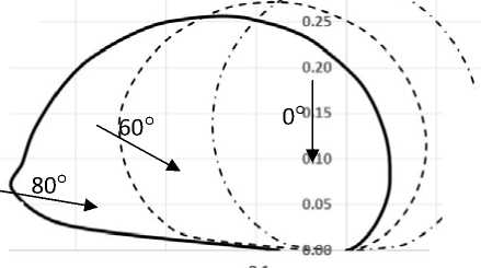
Erosion of mesh when exposed to a plasma jet.The mechanisms of the erosive effect of plasma jets of EJE on the SC were discussed in detail in [1; 18]. A peculiarity of the erosive effect of the EJE jets on the LTA mesh is that the angles of incidence of ions on the surface of the threads are in the range from 0 to 90 ° at practically any angle of incidence of ions on the surface of the LTA mesh θ [19]. To illustrate this effect, fig. 1 shows the results of calculating the depth of erosion of a reflecting coating at different values of the angle θ.
Fig. 1 shows that the nature of the coating wear weakly depends on θ. Erosion occurs almost uniformly over the entire irradiated surface of the threads, which is due to the nature of the dependence of the sputtering relative coefficient of a continuous surface on the angle of ions incidence S (6) [20]. At the points of the threads facing the engine, θ = 0 (if a thread is perpendicular to the jet axis) and S (6) = 1.
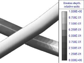
θ = 0°
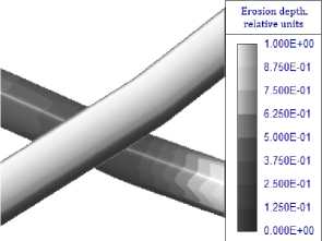
θ = 30°
Fig. 1. Erosion depth of conducting coating (in fractions of thickness) for different angles of ion incidence on the mesh surface θ (axis Y – erosion depth)
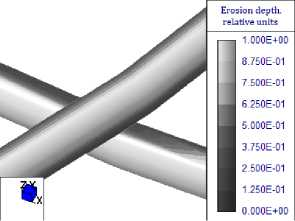
θ = 60°
Рис. 1. Глубина эрозии проводящего покрытия (в долях толщины слоя) при различных углах падения ионов на поверхность сетеполотна θ
а
b
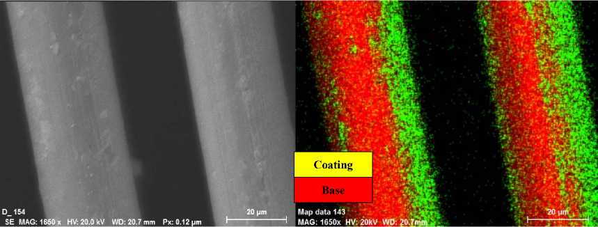
Fig. 2. Micrographofmesh threads ( a ) and a map of the elemental composition of their surface ( b ) in the vicinity of the point of complete sputtering of the reflecting coating
Рис. 2. Микрофотография нитей сетеполотна ( а ) и карты элементного состава их поверхности ( б ) вблизи точки полного распыления отражающего покрытия
On the lateral surface of the threads θ increases, and the ion flux density decreases proportionally to cos (θ). But in this case S (θ) increases, which compensates for the decrease in the current density. Thus, over most of the irradiated surface of the threads, the sputtering rate changes insignificantly.
This type of wear leads to the fact that at some point of time the reflective coating disappears immediately from almost the entire irradiated surface of the threads; thereafter the wear of the base begins.
Fig. 2 shows a micrograph of the surface and a map of the elemental composition of the mesh threads in the vicinity of the point of complete sputtering of the reflecting coating, obtained by SEM.
As it can be seen from fig. 2, the boundary of the complete sputtering of the reflecting coating is rather sharp, which confirms the conclusion about the complete coating sputtering from the entire irradiated surface of the thread.
Degradation of the mesh reflection coefficient . The degradation of the mesh reflection coefficient when the reflecting coating is sputtered is associated with decreasing the conductivity of the surface layer and increasing the contact resistance of the threads. In a complete formulation, the construction of a mathematical model of this effect is an extremely difficult task; therefore, in the framework of this work, the dependence of the reflection coefficient on the degree of exposure to the plasma jet of the EJE was determined experimentally.
Measurements of the reflection coefficient of the mesh samples in the operating frequency range were carried out before and after the impact of the jet. The degree of jet impact on the mesh was determined by calculation. In this case, the following parameters of the reflecting coating wear were used:
, (1)
ϑ = s =
Sputtered reflecting coating mass
9 m = ТТ^НТПУПГТЗТТТТГТ??^ (1.а)
9 = ?/£^™^Э^^ (1.b)
b where 9s is wear rate for area; 9m is wear rate for mass; 9b is wear rate for thickness.
The calculation of 9 $ and 9 m was carried out by integrating the corresponding parameters over the surface of the threads on the area of a fragment containing a sufficiently large number of mesh cells. The calculation took into account the mutual shielding of the threads. The value 9 h was determined from the ratio of the maximum erosion length (the depth of erosion of a semi-infinite target) to the initial layer thickness h 0 . The calculated dependences of the wear degree of the reflecting coating on the exposure time at different angles of ions incidence are shown in fig. 3.
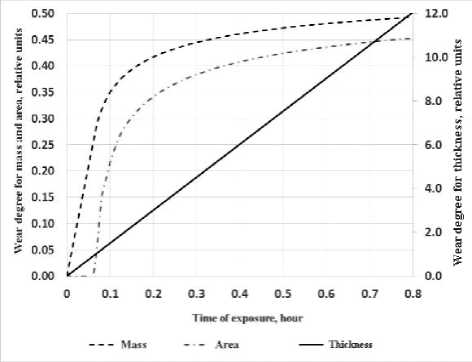
Fig. 3. Dependence of wear degree of reflective coating on the time of exposure to a plasma jet
Рис. 3. Зависимость степени износа отражающего покрытия от времени воздействия плазменной струи
Fig. 3 shows that the degrees of wear for area and mass asymptotically approach their limiting value of 0.5, and the degree of wear for thickness increases linearly with time. The degree of wear for area does not start to change immediately, but only after some time, corresponding to the sputtering of the reflecting coating to the entire depth, i. e. when 9 h ~ 1. The wear degree for mass initially grows rapidly, but the growth rate slows down after sputtering a significant part of the coating.
It should be noted that 80 % of wear for mass is achieved when the reflecting coating is sputtered to a depth of about (2–3) h 0 , and 80 % of wear for area is achieved when the reflecting coating is sputtered to a depth of about 6 h 0 . This indicates that the side surfaces of the threads are sputtered much more slowly than the surfaces facing the engine. Apparently, the coating at the points of threads contactis sprayed even more slowly.
The analysis showed that the degree of wear for thickness 9h is the most suitable for constructing an empirical dependence of the reflection coefficient on the degree of reflecting coating wear. Application of 9$ and 9m leads to significant errors, since the calculation of 9$, 9m near their limiting value (at 9h >> 1) is inaccurate due to the inaccuracy of the geometric model of the mesh.
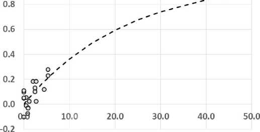
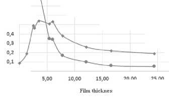
Fig. 4 shows the results of measurements of the mesh reflection coefficient depending on the degree of wear for the reflecting coating thickness. In the experiment the ion current density and the time of exposure to the samples were varied. In total, 18 samples were irradiated. Values of 9 h from 0.5 to 44 were realized on them.
Taking into account the large variations in the measured values of the reflection coefficient, the following function was used to approximate the dependence of the reflection coefficient of the electromagnetic radiation of the LTA reflector mesh on the degree of the reflecting coating wear (in fig. 4 it is shown by a dotted line):
^ R = R max { 1 - exp ( -P-9 h ) } , (2)
where Δ R max is the maximum degradation of the reflection coefficient of the mesh electromagnetic radiation; β is an adjustable parameter determined from the experiment.
As it can be seen from fig. 4, the value of Δ R ≈ R max is achieved at 9 h >> 1. Allowable JR values were maintained at 9 h < 15-20 depending on the signal frequency. In this case 9 s and 9 m ~ 0.5. This fact suggests that the sputtering of reflecting coating from the surface of the threads does not significantly affect the reflection coefficient. Apparently, sputtering of the coating at the points of threads contacts is more significant. This hypothesis is confirmed by a significant change in the reflection coefficient when changing 9 h from 5 to 44 (see fig. 4).
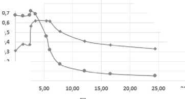
In addition, strong dependence of the reflection coefficient on the type of mesh weaving was found during the experiment. Fig. 5 shows the values of Δ R/R max of two mesh samples differing in the type of weaving.
Fig. 5 shows that the mesh of type 1 has significantly higher resistance to the effect of a plasma jet than the mesh of type 2. The reason for such strong difference is, apparently, the different degree of protection of the points of threads contacts from the action of ions. Hence it follows that the type of weaving is an important parameter and it must be taken into account when choosing mesh and assessing the resistance of LTA to the effect of plasma jets of an EJE. To confirm the durability of the mesh, it is necessary to test it.
Since the effect of the plasma jet on the LTA occurs unevenly over the surface of the reflector and, accordingly, the degree of wear is different for each section of the reflector, the calculation of the change in the LTA reflection coefficient as a whole is performed by averaging over all sections:
R = Z R i S i , (3)
Stot i where Stot is the total area of the reflector; Si is the area of the section; Ri is the reflection coefficient of the section (calculated by the formula (2) for the estimated degree of wear of the section 9hi).
The authors calculated the wear degree of the LTA reflector mesh of the experimental SC. The calculation was carried out for the case of the simultaneous action of two CEs (correcting engines) located on opposite sides of the SC body and installed at different angles. The operating time of both engines corresponded to the SC RAL.
In the course of the calculation it was found that at the end of the RAL the reflecting coating will be completely sputtered over about 35 % of the reflector area. The reflecting coating remains on the rest of the surface. The maximum degree of the coating wearin depth reaches 17, the wear of the base is less than 1 %.
At this level of exposure, the change in the reflection coefficient at the point with the maximum coating wear ( 9 h ~ 17) is close to the maximum permissible value of Δ R per . But since the coating wear is much less on most of the reflector, the degradation of the antenna reflection coefficient as a whole is guaranteed not to exceed Δ R .
per
However with a different structural-layout scheme (SLS) of the SC the impact on the LTA may be critical, therefore, the problem of choosing the SC SLS in which the effect of the CE plasma jet on the LTA will not exceed the permissible level is very urgent.
The TRC contamination with the products of the mesh sputtering. Particles of metal, mainly reflecting coating, sputtered from the surface of the mesh threads, can be deposited on the surface of the TRC changing their thermo-optical characteristics. In this regard it becomes necessary to determine the thickness of the contamination films formed on the surface of the TRC during the entire time of the SC operation in orbit, as well as the optical properties of these films and their influence on the thermo optical characteristics of the TRC.
The deposition fluxes of particles on the TRC surface are calculated by integrating the sputtering fluxes over the entire surface of the LTA exposed to the plasma jet:
nV c = J I n—L 2 1 n d (9 A , r AB ) cos ( 9 b ) dS , (4)
s П |ГАв| where rAB is the radius vector connecting the point of the sputtered surface "A" and the point of the surface on which the sputtered products "B" are deposited; nvc is flux density of sputtered particles at point "A"; θA is the angle of incidence of ions on the sputtered surface at point "A"; θB is the angle of incidence of sputtered particles at point "B"; In d (oA, rab ) is the sputtering indicatrix. In its turn, nvs is calculated as:
J, cos(0J 7
nvs = - b ' J f ( E ) ■ S ( E , o A w , (5)
where Ji is the ion current density; E is the ion energy; f ( E ) is the ion distribution function according to energy; S ( E , 0 A ) is the dependence of the sputtering coefficient on the energy and the angle of ions incidence; e is the electron charge.
Thus, to calculate nv c in addition to the parameters of the plasma jet, it is necessary to know the characteristics of the mesh sputtering, namely, the sputtering indicatrix I n d ( o A , r ab ) and the sputtering coefficient S ( E , 0 A ).
Just as for smooth solid surfaces, the coefficient of sputtering of the mesh surface can be defined as the ratio N
S = N a- , where N a is the number of atoms sputtered from the surface of the mesh threads per unit time; N i = J i cos ( 0 ) / e is the number of ions falling on the reflector surface.
However, unlike smooth surfaces Na is calculated by integrating the flux density of sputtered particles nvS over the surface of the threads.
1.0
Wear degree for thickness, relative units
о Exponential ---Approximation
Fig. 4. Change in the mesh reflection coefficient depending on the degree the reflective coating wear
Рис. 4. Изменение коэффициента отражения сетеполотна в зависимости от степени износа отражающего покрытия
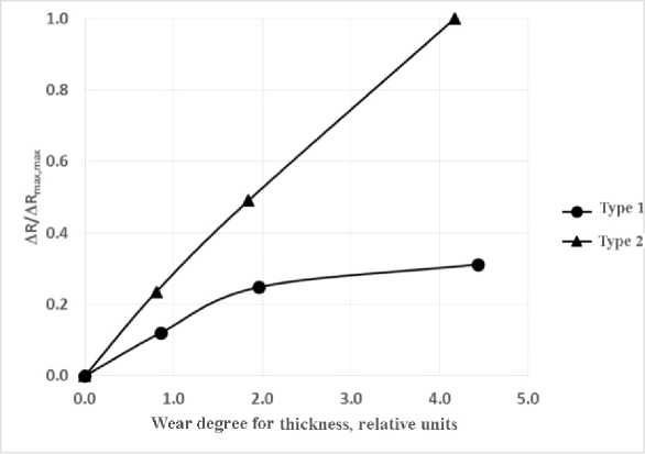
Fig. 5. Influence of weaving type on the change of the mesh reflection coefficient (values at all points are normalized by maximum value Δ R/R max ), axis Y – degree of wear for thickness
Рис. 5. Влияние типа плетения на изменение коэффициента отражения сетеполотна (значения во всех точках нормированы по максимальному значению Δ R max , max )
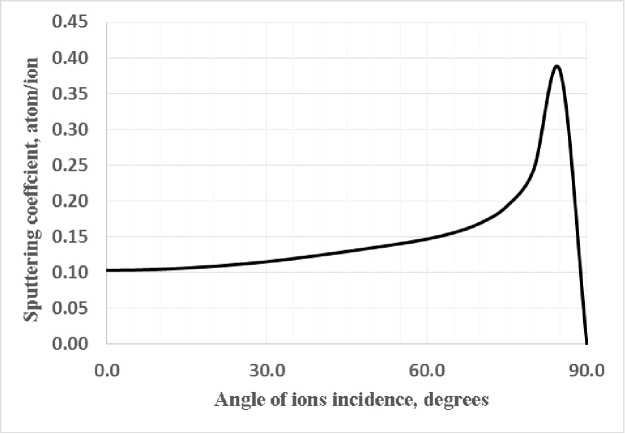
Fig. 6. Dependence of the mesh sputtering coefficient on the angle of ions incidence
Рис. 6. Зависимость коэффициента распыления сетеполотна от угла падения ионов
A three-dimensional computational model of the mesh containing a sufficiently large number of elementary cells is used to calculate nvS .
Fig. 6 shows the calculated dependence of the mesh sputtering coefficient when it is exposed to a plasma jet of the EJE.
As you can see from fig. 6, the angular dependence of the mesh sputtering coefficient differs significantly from the angular dependence of a solid surface [20]. At 9 < 60-70° the ion flux Ni decreases proportionally to cos (9), while Na changes only slightly, since the total cross section of threads interacting with the flux remains almost unchanged.
At 9 > 60-70 ° the mesh geometric transmittance tends to zero and almost all the ions of the jet fall on the surface of the threads. Therefore, there is a rapid growth of S here. At 9 = 90 ° N i = 0 and, correspondingly, S = 0.
Let us note that the mesh sputtering coefficient at 9 = 0 corresponds to the sputtering coefficient of the solid material, corrected for the mesh geometric transmittance:
S « S au -( 1 - T ) , (6) where T is the mesh geometric transmittance.
The mesh sputtering indicatrix (fig. 7) also has a number of significant differences from the sputtering indicatrix of smooth materials.
From fig. 7 it can be seen that at sliding angles of incidence, most of the mesh sputtering products are directed towards the ion source, while on smooth surfaces it is directed away from the source. This is due to the fact that the sections of the threads that are directed to the source are sputtered at an oblique incidence of ions.
It should also be noted that when sputtering mesh surfaces, the streams of sputtered particles also spread to the rear hemisphere, since particles from the surface of the threads are emitted in almost all directions.
The calculation of the contamination of the of the surfaces of the experimental SC developed by JSC Academician M. F. Reshetnev “Information Satellite Systems” by sputtering products of the reflecting coating of the LTD reflectorwas carried out.
Calculations show that the maximum thickness of the deposited film on the side surface of the SC body is about 1.5 nm, and the surface density of contaminants is 3 ∙ 10-6 g / cm2. It should be noted that the film will consist not only of gold atoms, but also of the mesh base atoms (tungsten or molybdenum), as well as of particles of its own external atmosphere [3], captured by the film.
Changes in the characteristics of TRCdepending on the level of contamination will be considered in the next section.
Degradation of the TRC thermo-optical characteristics . The deposition of thin metal films (products of the sputtering of the reflecting coating and the base of the mesh threads) on the surface of the TRC can lead to a significant change in their thermo-optical characteristics. Experiments to determine the dependence of the solar radiation absorption coefficient – A s and the emissivity (emissivity factor) – ε on the thickness of the deposited gold film on the surface of the TRC were carried out to study this issue at the PP-2 stand of Moscow Aviation Institute. A detailed description of these experiments and the data obtained is given in [21]. The objects of research were “mirror” coating of the OSO-S type and a film coating of the PM-OA type. The use of gold as a metal for deposition is due to the fact that it does not form oxide films in air. Films of other metals are rapidly oxidized, while their properties change greatly.
Mirror coating OSO-S is a thin plate made of K-208 glass with one-sided deposition of a layer of silver, glued to the metal plate with glass outside. Initial characteristics of the coating: A s = 0.08; ε = 0.85. The PM-OA film coating is made on the basis of the PM-1EU polyimide film with one-sided aluminum sputtering. Coating initial characteristics: As = 0.31; ε = 0.68.
The samples were rectangular plates 20x20 mm in size (OSO-S) and 30 × 25 mm (PM-OA), onto which thin gold films with a thickness of 1 to 24 nm were deposited by cathodic sputtering.
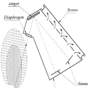
To apply the films, the TRC samples were placed in a protective casing (fig. 8), which protected the samples from sputtering products from the walls of the vacuum chamber.
The sputtering target was also placed inside the casing and was protected from sputtering products from the walls of the vacuum chamber. The jet ions passed through a special collimating hole (ceramics) and hit the target. A Hall engine of the M50 type was used as an ion source, accelerating xenon ions to the energy of ~ 300 eV. For the gas (recombined xenon ions) to escape from the casing, holes were made in its side walls, covered with plates, excluding the direct visibility of the target and samples from the side of the vacuum chamber. The sputtering products of the target were deposited on the TRC samples located immediately in front of it. The control of the mass deposited on the TRC samples was carried out using a quartz microbalance with a resonance frequency of 6 MHz (sensitivity 1.1 ∙ 10–8 g / cm2 / Hz). The sputtering process continued until the change in the frequency of the quartz resonator reaches a predetermined value.
Fig. 9 shows the results of measuring the thermo-optical characteristics of TRC with deposited gold films of various thicknesses.
It can be seen from these graphs that the nature of the change in the coefficients A s and ε, depending on the thickness of the contamination film d , is the same for both types of TRC. In the range d from 0 to 4 nm ε practically does not change. At d > 4 nm, ε rapidly decreases and at d = 24 nm reaches values comparable to ε of a monolithic material (for polished gold from 0.018 to 0.035).
The A s behavior is more complex. At d from 0 to 3 nm, a sharp increase in As is observed, in the range from 3 to 7 nm As reaches maximum and reaches a plateau, and at d > 7 nm it gradually decreases to values comparable to the A s of a monolithic material.
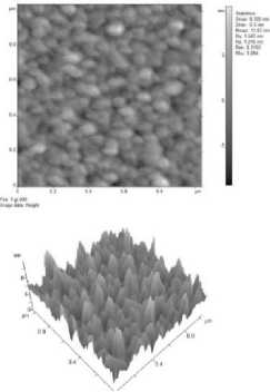
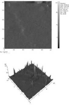
Such an unusual behavior of A s and ε is explained by the fact that the gold film with a thickness of up to 3–5 nm is granular. This is confirmed by the AFM images shown in fig. 10.
From fig. 10 it can be seen that at d = 2.7 nm almost all the granules have coalesced, and at d ≥ 6 nm, the film is almost a monolithic substance. With a small film thickness, while the granules have not coalesced yet, the film has very low conductivity. As d increases, the granules coalesce and the conductivity of the film rapidly increases, reaching the level of a monolithic material.
The presence of a thick reflective film leads to the fact that thermal radiation does not leave the material and its ε is comparable to ε of the film material. As long as the reflecting layer is not formed, the value of ε remains practically unchanged and is equal to ε of an uncontaminated TRC.
The nature of A s change is completely different. The rapid growth of A s at d from 0 to 3 nm is associated with resonant absorption of radiation arising on the grid structure of the film. With further increase in d , the value of the As coefficient gradually decreases, approaching the As of gold on the substrate.
Since the degradation of TRC is characterized by a change not in the individual As or ε, but in the As/ε ratio, films with thickness of less than 2–3 nm are critical for TRC, when a significant increase in As occurs with relatively small changes in ε.
|
/Z / / * ! 0 |
25'>x \ |
|
/ \60° i 0 / >'\a 1 d |
io | ! ' |
|
-/во ° X \ |
/ ' z 05 / Z / у # #* |
|
-0.4 -0.3 -0.2 -0.1 — ■ — 0 Degrees — — — 60 Degrees |
0.0 0.1 0. ^^^ 80 Degrees |
а
Fig. 10. AFM-images of contamination films on the OSO-S surface with a film thickness of 2.7 nm ( a ) and 6 nm ( b )
b
Рис. 10. АСМ-изображения пленок загрязнения на поверхности ОСО-С при толщине пленки 2,7 нм ( а ) и 6 нм ( б )
If we assume that the change in the ratio As/ε of TRC should not exceed 50 % of the initial value, from the data obtained it can be found that the permissible level of contamination of OSO-S with gold films is dlim = 0.3 nm (6 ∙ 10–7 ∙ g / cm2 ), and PM-OA – dlim = 1.7 nm (3.5 ∙ 10–6 g / cm2).
When thicker films are deposited ( d > 10–5 g / cm2), the characteristics of the TRC change catastrophically. The emissivity decreases to 0.3, and the absorption coefficient increases 2–3 times. In this case, the As /ε ratio can increase by a factor of 5–10.
It should be noted that since under real SC operating conditions, pollution films contain not only metals, but also other particles (carbon, silicon, organic matter), the conductivity of the films and, accordingly, the change in the As coefficient will be less than that of films made of pure metal. Therefore, the above dlim estimates are worst case estimates.
Conclusion. As a result of a set of theoretical and experimental work to determine the effect of the plasma jet of correcting electric jet engines on the functional characteristics of spacecraft, results were obtained that are of significant interest and practical importance in the field of designing and ensuring the resistance of modern automatic spacecraft to the impact of man-made factors.
It has been established in this work that the effect of plasma jets of correcting engines can lead to significant sputtering of the reflective coating from the surface of the reflector of a large-size antenna.
It has been shown experimentally that the sputtering of the coating at the points of contact and interweaving of the threads under the action of the jet plasma of the engines occurs much less intensively, which causes relatively high values of the reflection coefficients measured on the samples of the mesh with high degrees of wear.
It has been established that the contamination of the optically sensitive SC surfaces with the products of LTA sputtering can be significant and should be taken into account when choosing the structural-layout scheme (SLS) of the SC.
The paper shows the fundamental possibility of creating modern automatic spacecraft, which include large-size antennas and electric jet engines. The implementation of this opportunity can be achieved by the appropriate choice of the SLS, taking into account this impact.
References Influence of plasma jets of electric jet engines on spacecraft functional characteristics
- Testoyedov N. A., Kochura S. G., Maksimov I. A. [Study of the mechanisms and levels of the impact of the space environment on the spacecraft]. Vestnik SibGAU 2016, No. 6, P. 77–90 (In Russ.).
- Maksimov I. A., Kochura S. G. Issledovaniye vliyaniya faktorov kosmicheskogo prostranstva i tekhnogennykh faktorov na kosmicheskiye apparaty, razrabotka metodov i sredstv zashchity [Study of the influence of space factors and man-made factors on spacecraft development of methods and means of protection]. Krasnoyarsk, 2011, 182 p.
- Novikov L. S., Mileev V. N. et al. [Spacecraft charging in the magnetospheric plasma]. Model kosmosa, 2007, Vol. 2, 1127 p. (In Russ.).
- Testoyedov N. A., Kochura S. G., Maksimov I. A. et al. [Erosion impact of plasma jets of electric propulsion engines on the network of large-size aerials of automatic spacecraft]. Naukoyemkiye tekhnologii. 2016, No. 7, P. 17 (In Russ.).
- Vlasova N. A., Getselev I. V., Ivanova T. A. et al. [Monitoring the level of radiation conditions on highapogee spacecraft]. Kosmonavtika i raketostroenie. 2003, No. 1(30), 6 p. (In Russ.).
- Sosnovets E. N., Vlasova N. A., Ivanova T. A. et al. [Control of the level of radiation impact of cosmic radiation on geostationary spacecraft Express-A2, A3 in maximum of 23th solar activity cycle (2000–2002)]. Voprosy atomnoy nauki i tekhniki. Seriya: fizika radiat sionnogo vozdeystviya na radioelektronnuyu apparaturu. 2003, No. 1–2, P. 3–7 (In Russ.).
- Nadiradze A. B., Rakhmatullin R. R., Kochura S. G. et al. [Features of the experimental determination of the resistance of composite materials to the erosion effect of STP]. Vestnik SibGAU. 2012, No. 1 (41), P. 91–96 (In Russ.).
- Tverskaya L. V., Balashov S. V., Veden’kin N. N. et al. [Outer radiation belt of relativistic electrons in the 23rd solar cycle minimum]. Geomagnetizm i aeronomiya. 2012, Vol. 52, No. 6, P. 779–784 (In Russ.).
- Ivanov V. V., Maksimov I. A., Nadiradze A. B. et al. [Methodology for ensuring the durability of onboard equipment and the spacecraft as a whole under SPT plasma conditions]. Vestnik SibGAU. 2006, No. 1 (8), P. 76–81 (In Russ.).
- Nadiradze A. B., Maksimov I. A., Smirnov V. A. et al. [An experimental study of the contaminating effect of its own external atomosphere at the stage of orbital operation of a spacecraft]. Vestnik SibGAU, 2006, No. 1 (8), P. 91–96 (In Russ.).
- Smirnov V. A., Shatrov A. K., Maksimov I. A. et al. [Study of the polluting effect of its own external atmosphere and plasma of SPT on spacecraft Express-AM]. Vestnik SibGAU. 2006, No. 2 (9), P. 46–50 (In Russ.).
- Nadiradze A. B., Chirov A. A., Shaposhnikov V. V. et al.[Computional model of plasma penetration of electric propulsion engines into instrumental compartments of spacecraft]. Vestnik SibGAU. 2006, No. 3 (10), P. 49–52 (In Russ.).
- Nadiradze A. B., Chirov A. A., Shaposhnikov V. V. et al. [Evaluation of the degassing time of a leaking equipment compartment]. Vestnik SibGAU. 2007, No. 1 (14). . 95–99 (In Russ.).
- Maksimov I. A., Smirnov V. A., Ivanov V. V., Nadiradze A. B. [Increasing the reliability of the leaky compartment of the spacecraft]. Vestnik SibGAU. 2007, No. 1 (14), P. 88–91 (In Russ.).
- Smirnov V. A., Tibil’deyeva V. V., Maksimov I. A. et al. [Study of impact of SPT jets on structural elements of large-sized antennas]. Vestnik SibGAU. 2007, No. 1 (14), 7 p. (In Russ.).
- Ivanov V. V., Maksimov I. A., Nadiradze A. B., Shaposhnikov V. V. [Mechanisms of the effect of the plasma of electric rocket engines on the operation of the onboard equipment of spacecraft]. Vestnik SibGAU. 2007, No. 3 (16), P. 87–91 (In Russ.).
- Nadiradze A. B., Shaposhnikov V. V., Maksimov I. A. et al. [Selection of a ctriterion and cosiderration of the composition of pollution films when assessing the joint polluting effect of its own external atmosphere and stationary plasma engines]. Vestnik SibGAU. 2007, No 4 (17), P. 91–94 (In Russ.).
- Nadiradze A. B., Shaposhnikov V. V., Smirnov V. A. et al. [Study of the erosion effect of jets of SPT on radioreflecting set-cloth of large-sized aerials of spacecraft]. Vestnik SibGAU. 2008, No. 4 (21), P. 120–124 (In Russ.).
- Ivanov V. V., Maksimov I. A., Nadiradze A. B., Shaposhnikov V. V., Smirnov V. A. [Model of penetration of plasma formations formed during the operation of electric propulsion engines into non-hermetic equipment compartment of spacecraft]. Materialy mezhdunarodnoy konferentsii “Aviatsiya i kosmonavtika”. Moscow, 2006, P. 357 (In Russ.).
- Kim V. P., Nadiradze A. B., Popov G. A. et al. [Problems of using electric rocket engines on spacecraft]. V kn. “Model’ kosmosa”, Vol. 2 «Vozdeystviye kosmicheskoy sredy na materialy i oborudovaniye kosmicheskikh apparatov». Ed. L. S. Novikova. Moscow, Universitet Publ., 2007, P. 615–659.
- Balashov S. V., Blyakharskiy Ya. S., Nadiradze A. B. [Calculation of sputtering characteristics of mesh surfaces when exposed to them by plasma jets of SPT]. tezisy dokladov XXI Mezhdunarodnoy konferentsii po Vychislitel’noy mekhanike i sovremennym pricladnym programmnym systemam (VMSPPS’2019). 2019, Alushta (In Russ.).
