Information-measuring system of pyrometric type for small-sized unmanned aircraft

Author: Akzigitov A. R., Pisarev N. S., Statsenko N. I., Neverov U. A., Akzigitov R. A.
Journal: Siberian Aerospace Journal @vestnik-sibsau-en
Section: Aviation and spacecraft engineering
Article in issue: 4 vol.20, 2019.
Free access
A new trend of science and technology is now rapidly developing both in Russia and abroad – the development of miniature unmanned aerial vehicles. The key system of on-board control equipment (avionics) of an unmanned aerial vehicle (UAV) is the orientation system for determining UAV attitude relative to reference system. In small-size UAV, we can meet the application of strapdown attitude reference systems, magnetometric, pyrometric, video systems, etc. Rapid development of mini- and micro-UAVs requires the development of information-measuring systems (operating on different physical principles) in order to determine UAV attitude parameters in flight. With UAV mass and wingspan reduction, there are growing requirements for these systems, concerning the accuracy of positioning parameters and more compact dimensions. Manufacturing of most information-measuring and control systems of manned aircraft and heavy UAVs rely on traditionally used gyroscopes and accelerometers. They are complex fine-mechanics instruments of considerable power consumption, rather large size, weight and high cost. A significant improvement of the accuracy in UAV angular coordinates determination is achieved by integrating orientation systems of various types. The use of GPS / GLONASS signals also improves the accuracy and reliability of determining UAV angular coordinates and supplies the additional function of measuring its geographical coordinates.
Information-measuring system, unmanned aerial vehicle, pyrometric sensor.
Short address: https://sciup.org/148321706
IDR: 148321706 | UDC: 656.7.076 | DOI: 10.31772/2587-6066-2019-20-4-452-457
Text of the scientific article Information-measuring system of pyrometric type for small-sized unmanned aircraft
Introduction . The proposed model relates to devices measuring aircraft (AC) attitude, and can be used as a device for orientation and stabilizing of small-size unmanned aerial vehicles.
There is a free-running orientation system that supplies the angle values of a moving object successive revolutions, known as Krylov angles, to be taken as orientation parameters. It consists of three angular velocity sensors, the sensitivity axes of which are normal to each other, and the angle calculators, the main elements of which are angular velocity calculators for Krylov angles, plus integrating and summing devices [1–3].
The disadvantage of the free-running orientation system is time-dependent errors in determining the object’s attitude, due to the presence of integrating links in the attitude rate sensor.
Pyrometric vertical. The closest analogue is the pyrometric vertical as part of the Co-Pilot CPD4 (fig. 1) model aircraft autopilot designed by FMA Inc (USA, Maryland).
This vertical consists of four pyrometric sensors (pyrometers) located horizontally on the printed board in the aircraft plane [2–5]. The principle of attitude determination is based on measuring the difference in infrared (thermal) radiation from the earth surface and from the sky (fig. 2). Since the earth is always warmer, there is a certain gradient distributed vertically from the zenith to the nadir.
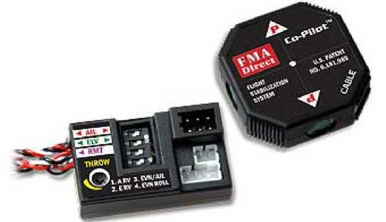
Fig. 1. Co-Pilot CPD4
Рис. 1. Co-Pilot CPD4
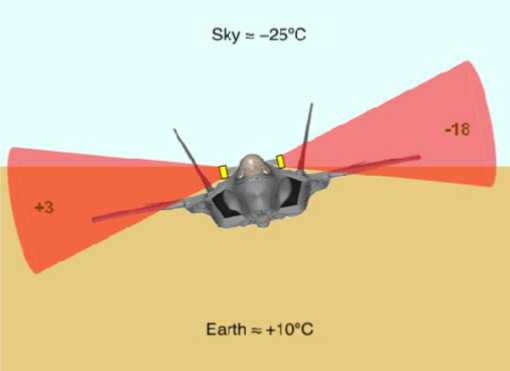
Fig. 2. Gradient between sky and earth
Рис. 2. Градиент между небом и землей
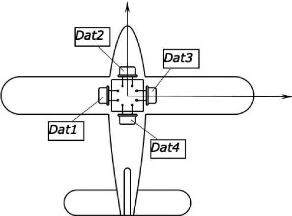
Fig. 3. Pyrometric sensors location
Рис. 3. Расположение пирометрических датчиков
Measuring the temperature with four perpendicular pyrometers located along the axes of symmetry of the aircraft, it is possible to determine bank and pitch angles without accumulating errors due to the absence of integrating links [6–9].
The known pyrometric vertical has the drawback of inability to operate in the absence of visible horizon (when flying in deep gorges, tunnels, along city streets) and with uneven thermal pattern on the opposite sides of the aircraft (for example, when there is a forest fire to the right and a cold sea to the left) [10; 11]. In the first case, the pyrometric vertical will not be able to function at all; the second case implies a significant error in determining bank and pitch angles (fig. 3).
Technical objective. The technical objective of the proposed device is to expand the capabilities of the pyrometric vertical by adding the function of controlling the accuracy of angles calculated by that pyrometric vertical and of bank and pitch angle calculation in the absence of visible horizon or in conditions of uneven thermal pattern [12–14].
The technical problem is solved by additional installation into the pyrometric vertical (containing four pyrometers on a printed board set perpendicularly in the same plane), a biaxial or three-axis unwedging angular velocity sensor independent of the pyrometers, and with the sensitivity axis parallel to the symmetry axes of the aircraft. The angular velocity sensor itself is located in the aircraft center of mass, and has the function of controlling the accuracy of bank and pitch angles. The pyrometers’ readings are taken to calculate only dryness; the calculation of bank and pitch angles is also performed, but only by indications of the angular velocity sensor within a limited period (when the bank and pitch angles supplied by pyrometers are considered incorrect). In conditions unfavorable for the pyrometric vertical, it becomes possible to instantly switch the task of attitude calculation from the pyrometric vertical to the angular velocity sensor
(AVS), using the last correct reading of the pyrometric vertical as the initial bank and pitch angle value, and also to detect unfavorable conditions according to the AVS readings.
The utility model is illustrated by drawings, where fig. 4 shows a configuration of the pyrometric vertical together with non-serviceable AVS. The proposed device contains a printed board 1, on which four pyrometers 2 are perpendicular to each other and in the same plane, located in the same plane (the printed board 1 is installed in the aircraft so that the direction of pyrometers’ sensitivity axes is parallel to the aircraft axes of symmetry), and two- or three-axis AVS 3 located in the aircraft center of mass with sensitivity axes parallel to the axes of symmetry of the aircraft. Pyrometers and AVS are linked with computer 4.
The introduced device performs as follows: in the standard mode, the calculation of bank and pitch angles is performed only by the readings of the pyrometers 2. In flight, the bank and pitch angles are continuously measured according to the readings of the pyrometers 2 integrated in the pyrometric vertical, and AVS 3; the recent readings are accumulated in the RAM of computer 4, and compared (fig. 4).
The execution of sensor readings’ inequalities means that the readings of the pyrometric vertical and of independent AVS for the latest meterage are correlated, and the pyrometric vertical works correctly. With this φg, AVS pitch angle is assigned the value of the pyrometric vertical pitch angle, and the AVS bank angle – the value of the pyrometric vertical bank angle, and the reading of the AVS angular position restarts every time from the last value supplied by the pyrometric vertical. Thus, continuous monitoring of the angle accuracy supplied by the pyrometric vertical is supported. As the integration errors do not get accumulated, the reliability and multi-functional operation of the given device are perfected, as compared with the known units [15].
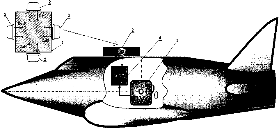
Fig. 4. Location of pyrometric sensors together with angular velocity sensor
Рис. 4. Расположение пирометрических датчиков совместно с датчиком угловой скорости
In case of the inequalities’ non-execution, the assignment of angles does not occur. If the inequalities are not executed in succession of times set by the construction, the operating conditions of the pyrometric vertical are considered unfavorable, and the task of bank and pitch angle calculations is fully transferred to AVS, by integrating the readings of which the current bank and pitch angles relative to their last correct values are obtained. Switching to AVS can also be performed at the command of the aircraft pilot or UAV operator. The values of other parameters are assigned specially for the presently operated aircraft and autopilot.
The most commonly used AVS have their own reduction rate of 0.33 degrees per minute. As the aircraft configuration allows, they may be able to maintain the stabilization with bank and pitch angle error from 1 (for not self-stabilizing aerodynamic designs) to 5 degrees (for self-stabilizing aerodynamic designs). Thus, with the accumulation of errors of bank and pitch angle readings at the rate of 0.33 degrees per minute, the aircraft can go on stable using the readings of the non-serviceable AVS from 3 to 15 minutes, which allows not only to get out of the zone unfavorable for the pyrometric vertical operation, but also to carry out short-term flights in gorges, tunnels and city streets.
Returning to stable flight by the pyrometric vertical readings is possible with execution of inequalities several times running.
As the stable flight according to the pyrometrical vertical readings is resumed, the values of bank and pitch angles are reset, and the attitude reading by AVS starts again as before, from the last correct value determined by the pyrometric vertical – that allows to exercise AVS control many times over without accumulation of integration errors.
Thus, the combination of device attributes appropriate for implementation allows to extend the pyrometer functions as to the vertical – in the absence of the visible horizon or in conditions of uneven thermal pattern – by intro- ducing the control of accuracy calculated only by bank and pitch angle pyrometer readings, and calculation of the same angles only by indications of the angular velocity sensor within a limited period, when the bank and pitch angles supplied by pyrometers are considered incorrect.
Conclusion. The article analyzes the characteristics of information-measuring system of pyrometric type in application for small-sized unmanned aerial vehicle. The advantages of applying the system are evident on the background of drawbacks demonstrated by the orientation system used to determine UAV attitudes relative to the reference system.
The reviewed way of using pyrometric sensors can help to considerably improve the accuracy of UAV angular coordinates determination.
References Information-measuring system of pyrometric type for small-sized unmanned aircraft
- Gal'kevich A. I. Nizkoorbital'naya kosmicheskaya sistema personal'noy sputnikovoy svyazi i peredachi dannykh [Low-orbit space system of personal satellite communication and data transmission]. Moscow, Yulis Publ., 2013, 170 p. (In Russ.).
- Kuzovnikov A. V., Testoedov N. A., Agureev V. A. [Problems of development of low-orbit multifunction personal satellite communication system GONETSD1M]. Vestnik SibGAU. 2013, Vol. 52, No. 6, P. 158–163 (In Russ.).
- Akzigitov A. R., Statsenko N. I., Pisarev N. S., Efimova A. N., Andronov A. S. Aircraft monitoring in remote areas via the low-orbit satellite communications system IRIDIUM along with the GSM data transmission through ASC-6 telemetry terminal. Siberian Journal of Science and Technology. 2017, Vol. 18, No. 3, P. 552–557.
- Shevchuk D. V. [The time estimate message delivery system "GONETS" for various variants of construction of the orbital group]. Radiotekhnika. 2012, No. 11, P. 127–130 (In Russ).
- Mukhin I. E., Shevtsov A. N., Shchitov A. N. [Prospects for the use of the multifunctional personal satellite communication system MSPSC GONETS]. Infokommunikatsii i informatsionnaya bezopasnost': sostoyanie, problemy i puti resheniy a: Materialy II Vserossiyskoy nauchno-prakticheskoy konferentsii [Infocommunication and information security: status, problems and ways of solution: materials of the II all-Russian scientific-practical conference]. Moscow, 2015, P. 151–155 (In Russ.).
- Zharov A. A. [Multifunctional system for personal satellite communications “Gonets-D1M”: state and prospects of development]. Tekhnologii i sredstva svyazi. 2013, Vol. 2, No. 6, P. 72–78 (In Russ.).
- Akimov A., Poleshchuk V. [Spatial accessibility and operational readiness of the low-orbital group of communication spacecraft]. Tekhnologii i sredstva svyazi. 2014, Vol. 2, No. 6, P. 76–81 (In Russ.).
- Antamoshkin O. A. [Design of highly reliable real-time systems]. Trudy MAI. 2011, No. 45, P. 61–63 (In Russ.).
- Marinich A. N., Pripotnyuk A. V., Ustinov Yu. M. [Monitoring of ships along the Northern sea route using satellite communication systems]. Vestnik Gosudarstvennogo universiteta morskogo i rechnogo flota im. Admirala S. O. Makarova. 2016, No. 6, P. 184–205 (In Russ.).
- Akimov A., Shevchuk D., Danilov D. [Efficiency of information transfer in low-orbit communication system with message transfer onboard spacecraft]. Tekhnologii i sredstva svyazi. 2015, No. 1, P. 69–72 (In Russ.).
- Akimov A., Shevchuk D., Danilov D. [Efficiency of information transfer in low-orbit communication system with message transfer onboard spacecraft]. Tekhnologii i sredstva svyazi. 2015, No. 2, P. 72–75 (In Russ.).
- Tsisar L. [The best satellite communications expands standards]. Tekhnologii i sredstva svyazi. 2008, No. 64, P. 40–42 (In Russ.).
- Bisterfel'd O. A. [The algorithm for moving data through communication channel with the segment of satellite communications]. Nauka i obrazovanie. 2014, No, 10, P. 41–43 (In Russ.).
- Kartavtsev D. V., Oblienko A. V., Oblienko M. V. [Organization of communication via satellite stations such as VSAT]. Pozharnaya bezopasnost': problemy i perspektiv. 2014, No, 5, P. 360–363 (In Russ.).
- Nazarov S. N. [Improving communication efficiency of mobile subscribers through the integration of cellular and satellite communication systems]. Vestnik Ul'yanovskogo gosudarstvennogo tekhnicheskogo universiteta. 2010, No. 52, P. 53–56 (In Russ.).
