Integrating Occlusion and Illumination Modeling for Object Tracking Using Image Annotation
Author: Amarjot Singh, Devinder Kumar
Journal: International Journal of Image, Graphics and Signal Processing(IJIGSP) @ijigsp
Article in issue: 10 vol.4, 2012.
Free access
Tracking occluded objects at different depths has become as extremely important component of study for any video sequence having wide applications in object tracking, scene recognition, coding, editing the videos and mosaicking. This paper experiments with the capabilities of image annotation contour based tracking for occluded object. Image annotation is applied on 3 similar normal video sequences varying in depth. In the experiment, one bike occludes the other at a depth of 60 cm, 80 cm and 100 cm respectively. The effect on tracking is also analyzed with illumination variations using 3 different light sources in video sequences having objects occluding one another at same depth. The paper finally studies the ability of annotation to track the occluded object based on pyramids with variation in depth further establishing a threshold at which the ability of the system to track the occluded object fails. The contour of both the individual objects can’t be tracked due to the distortion caused by overlapping of the object pyramids. The thresholds established can be used as a bench mark to estimate the capability of different softwares. The paper further computes the frame by frame error incurred by the system, supported by detailed simulations. This system can be effectively used to achieve flawless tracking as the error in motion tracking can be corrected. This can be of great interest to computer scientists while designing surveillance systems etc.
Image Annotation, Object Tracking, Depth, Occlusion, Contour
Short address: https://sciup.org/15012448
IDR: 15012448
Text of the scientific article Integrating Occlusion and Illumination Modeling for Object Tracking Using Image Annotation
Published Online September 2012 in MECS
Motion tracking plays an important role in the analysis of any video sequence. Over the years motion tracking is being applied widely in multiple fields like biomechanics [2], avionics [3], sport analysis [4], medical [5] etc. Despite the ability of the present systems, occlusion, depth variation, and blurriness are some of the issues which can hinder the effective object tracking. The real world video sequences consist of complex cases of occlusion that are difficult to handle thus occlusion. One of the tedious areas of interest with multiple applications like scene recognition, surveillance, object tracking etc is tracking occluded objects at different depths.
This paper focuses on using the annotation tool provided in [1] to label and track different objects in three similar video sequences varying in depth. The system provides a robust algorithm to track object in above mentioned complex occluded video sequences. The effort in labeling and tracking the object is greatly decreased by allowing the user to make as well as label the contour of object in any one frame followed by the automatic tracking of the contour in other frames. The human interaction plays a pivotal role in labeling the objects as the user can correct the label in different frames thus removing the error produced by the computer vision system, hence increasing the efficiency of the system.
The paper tries to analyze a very important and crucial aspect related to tracking occluded objects. Three similar videos having two moving objects, one occluding the other with variation in depth, were analyzed. In the videos two bikes, one occluding the other at depth 60 cm, 80 cm and 100 cm were analyzed. The results were explained on the grounds of pyramids. The effect on tracking is also analyzed with illumination variations using 3 different light sources in video sequences having objects occluding one another at same depth. The paper also computes the frame by frame error incurred by the system, supported by detailed simulations. Finally we establish a threshold at which the tracking ability of the systems fails. The threshold is established by computing the percentage overlap of contours of the two objects till both are not distorted. The contour of both the individual objects can’t be tracked due to the distortion caused by overlapping of the object pyramids after this threshold.
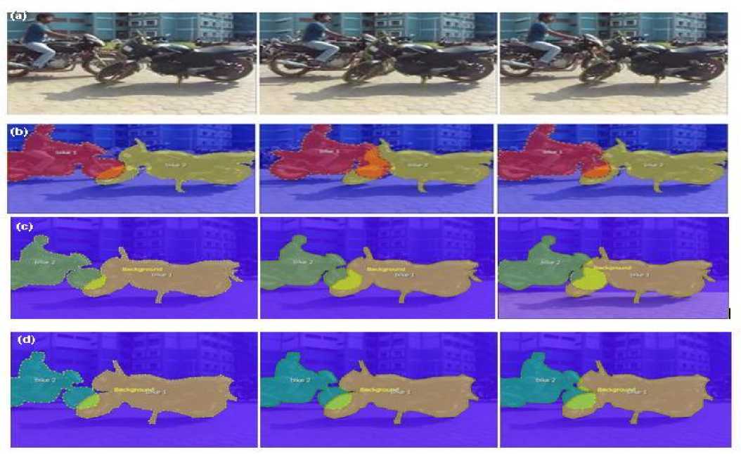
Figure. 1 a) Contour generated on the objects b) Annotated sequence for 60 cm depth c) Annotated sequence for 80 cm depth d) Annotated sequence for 100 cm depth
The following paper has been divided into four sections. The next elaborates the algorithm implemented by the paper for tracking the contour of the object. Section three explains the simulation results while the final section four, discusses the summary of the paper.
-
II. HUMAN BASED ANNOTATION
The system used in the paper makes use of human assisted layer segmentation, and automatic estimation of optical flow for object contour tracking. In order to increase the robustness of the system, the objective functions of flow estimation and flow interpolation are modeled on lagrange's L1 form [1]. Many techniques such as iterative reweighted least square (IRLS) [5, 6] and pyramid based coarse-to-fine search [4, 6] were used at large for the optimization of these non linear object functions.
-
A. Human assisted layer segmentation
This module works on the basis of human interaction with the labeling. The first step is the Initialization of contour in one frame. Due to background cluttering or other changes like shadow etc in the frame, errors can occur in the contour formed by the user. The error in contour can be corrected anytime by the user in any frame which is further automatically passed to the other frames. The forward and backward tracking of the target is simulated automatically by the system. Particle filter is used to track the object in the system as real time performance is considered more important than accuracy [7]. In addition, Occlusion handling technique has also been included in the contour tracker itself [1]. Suppose a function is defined using landmarks points as M = {ap : ap e R }, p=1 at frame F1. The motion vector p represents each landmark at frame F 2 . Depending upon whether the tracking is back or forth, the frame F 2 can be after or before F 1 . Instinctively, we want the movement of contour to be persistent and should match with the image features. In order for the movement to be persistent, we use optimization. The objective function is defined as:
TT
B ({ v p })= EE m p ( c ) | F 2 ((a , +Y p +c)-F i (a , + c)| + ю ^ S p |v p - V p+i | p = 1 c e Tp p = 1
v T + 1 = v T , where v is the motion vector. In the equation, the length between the contour points a p and a p + 1 is
l
Sp = -----=7
calculated by using the weightSp; we define lp + l where lp =|| ap ap+1|| and l is the average of lp . It’s evident from these equations that closer the points in the contour formation, more the probability that the points move together. Variable Tp is a square neighborhood at ap , while mp is the region of support for ap , a binary mask which indicates the presence of each neighboring pixel c inside the pixel, modulated by a two dimensional Gaussian function. In Eqn. (1) the objective function mentioned is nonlinear, hence taylor expansion is used to linearize the data term followed by the optimization of objective function performed through iterative reweighted least square (IRLS) [5, 6] and pyramid based coarse-to-fine search [4, 6]. In order to account for the changes in the lighting condition, the images in F 1 and F 2 contain the first and second order derivative of luminance instead of just RGB channels. The rigidity of the object is controlled by the coefficient ® .The user can set the value of ® before tracking.
For handling occlusion, the user is allowed to specify relative depth and the depth is automatically interpolated (as time function) for the rest of the frames. The contour tracker is driven by a 2nd-order dynamical model for prediction. The prediction is used as an initialization for optimizing Eqn. (1). The tracking algorithm iterates between the following two steps to handle occlusion:
-
(1) Check whether each landmark zp is occluded by other layers with smaller depth values. If occlusion is detected for z then set r p ( c ) = 0 , V c e N p in Eqn. (1). This means there is no region to support tracking zp .
-
(2) Optimize Eqn. (1) using the coarse-to-fine scheme.
The contour tracker worked fine for most of the cases, but it fails in case of drift from the position especially when the object rotates. To overcome this drawback, the system allows the correction of a landmark to be made at any frame and the change is transferred to the other frames. In the temporal propagation [1], to reconstruct the point modified by the user, the linear regression coefficients for the other points are estimated. The algorithm proposed works astonishingly well. In comparison to the complicated contour tracking/modification algorithm proposed in [8], are too expensive to be implemented for real-time long distance environments.
-
B. Layer by layer optical flow estimation
The mask showing the visibility of each layer is the main difference between layer by layer optical flow estimation and traditional flow estimation for the whole frame. The pixels lying inside the mask are only used for matching. For occlusion handling problem, apart from the normal procedure, outlier detection is also performed to segregate occlusion in the evaluation of optical flow to compensate the irregularity caused in the evaluation due to arbitrary shape of the mask.
For baseline line model for optical flow estimation the system uses optical flow algorithm [5,6], while to improve the accuracy symmetric flow, computation is included. Let E 1 and E 2 be the visible mask of a layer at frame F 1 and F 2 , ( g 1, h 1) be the flow field from F 1 to F 2 , and ( g 2, h 2) the flow field from F 2 to F 1 .
Following terms constitute the objective function for approximating the layer by layer optical flow. In the first step, the matching of images with the visible data term is formulated as mentioned in below:
B da L = J u * E 1( x , У ) I F 1( x + g 1 , У + h 0 - F 2 ( x , У ) I
B (2)
Where, u is the Gaussian filter. The data term data for ( g 2, h 2) is similarly defined. To account for outliers in matching, L1 norm is used. In the second step, smoothness is imposed by:
B S^ = J (| V g 1 | 2 + | V h 1 | 2 ) Y
Where Y varies between 0.5 and 1. Finally, symmetric matching can be achieved by:
B (1) = f| g 1( x + У ) + g 2 ( x + g 1, У + h 1)1 + sym J | h 1 ( x + у ) + h 2 ( x + g 1 , у + h 1 ) |
The sum of the above three equation objective function described below:
( j ) ( j ) ( j )
B (g 1 h 1-g 2- h 2) ^ Bdato + UBsmooth + ° Bsym j=1
(4) gives the
IRLS proposed in [5,6] is used as equivalent to outer and inner fixed-points, together with the coarse-to-fine search [4,6] and image wrapping for the optimization of this objective function. After computing the flow at each level of pyramid, the visible layer mask E 1 is approximated on the basis of estimated flow:
-
• if B 2 ( x + g i , y + h i ) = 0, then set B 1( x - y ) = 0 ;
-
• If in the Eqn. (4), the symmetry term is beyond the threshold at ( x , y ), then set E 1( x , y ) = 0 .
Same rule can be used to update E 2 . As coarse to fine technique is used for the algorithm, we get two bidirectional flow fields and cropped visible layer masks that exhibit occlusion. The user is allowed to change the values of G , ° and Y in Eqn. (5).
-
C. Human assisted motion labeling
On failure of optical flow estimation fails, the user by the help of feature points can specify the sparse correspondence between two frames. The system then automatically produces a parametric motion or interpolates a dense flow field based on the specified sparse correspondence. For the specification of sparse correspondence the user can either use the help of computer for increasing efficiency or manually, taking full control of motion annotation. Minimum SSD matching and Lucas-Kanade transform [7] is used by the system for finding the best match in the next frame for the feature point specified by user in previous frame. The system depends on the number of feature points specified to determine the mode of parametric motion i.e.
translation, affine transform or homography followed by the estimation of the motion parameters accordingly. The modes mentioned above can also be selected by the user directly and the user even have an option to choose to generate a smooth flow field interpolated using the preconditioned conjugate gradient algorithm.
However, defining corner like features for sequences in which only line structure is present can be a difficult task for these kinds of sequences. In order to solve this problem, uncertainty matching and probalisitic parametric motion were included in the algorithm so that the user can have a freedom to choose any pixel for correspondence. In the case of uncertainty matching, a probability map
w p ( x )
is produced to match the feature point p at location cp ∈ R. A mean χp and
∑ covariance matrix p are used to approximate the probability map Hp(x).For the determination of the probabilistic motion estimation, the system loops around two points. In the first step, the current estimate of mean and covariance are used for motion approximation. Mathematically, let s(cp;φ) : R → R be a parametric motion applied to the estimation of parametric motion computed by
φ * = argmin ∑ ( s ( c p ; φ ) - τ p ) T ∑ ( s ( c p ; φ ) - τ p ) φ p
p
In second step, estimation of the mean and covariance is done where a new probability map is used which is reweighted by the current motion
{ τ p , ∑ р } ← i p ( x ) Ν ( s ( c p ; φ *), ϕ 2 F )
Convergence of this algorithm occurs within a few iterations. A dense flow field (i.e. φ ) can also be obtained for the motion s ( cp ; φ ) . Also, the feature point specified by the user can be used in the next frame. For providing the human assistance the users interact with the tool through the interface provided in the system developed by the authors of [1].
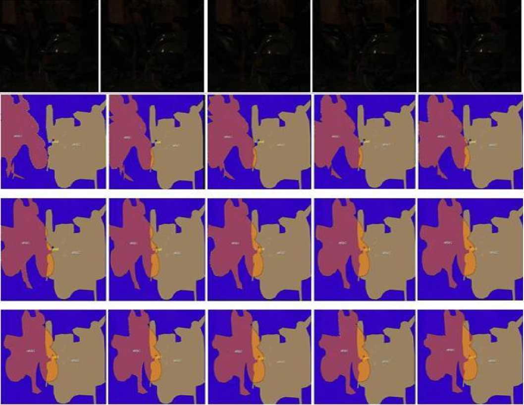
Fig. 2 a) Contour generated on the objects video with illumination variation b) Annotated sequence for 60 cm depth c) Annotated sequence for 80 cm depth d) Annotated sequence for 100 cm depth
Table 1. Error incurred during contour based tracking of each frame with respect to ground truth frame in percentage and pixels for at depth a) 60 b) 80 c) 100 (in cm)
|
Frame (a) |
Number of pixels |
Error in pixels with ground frame |
Error (%) w.r.t ground truth frame |
|
2 |
70339 |
0006 |
0.009 |
|
3 |
70295 |
00050 |
0.071 |
|
4 |
69337 |
01084 |
1.433 |
|
5 |
69063 |
01282 |
1.822 |
|
6 |
68244 |
02101 |
2.987 |
|
7 |
67851 |
02494 |
3.546 |
|
8 |
66375 |
03970 |
5.643 |
|
9 |
64420 |
05925 |
8.423 |
|
10 |
60496 |
09849 |
14.001 |
|
11 |
58082 |
12263 |
17.432 |
|
Frame (b) |
Number of pixels |
Error in pixels with ground frame |
Error (%) w.r.t ground truth frame |
|
2 |
70229 |
00009 |
0.012 |
|
3 |
70197 |
00041 |
0.058 |
|
4 |
69374 |
00864 |
1.234 |
|
5 |
69052 |
01186 |
1.689 |
|
6 |
68517 |
01721 |
2.45 |
|
7 |
68161 |
02077 |
2.957 |
|
8 |
66893 |
03345 |
4.763 |
|
9 |
64667 |
05571 |
7.932 |
|
10 |
61918 |
08320 |
11.843 |
|
11 |
59308 |
10930 |
15.561 |
|
Frame (c) |
Number of pixels |
Error in pixels with ground frame |
Error (%) w.r.t ground truth frame |
|
2 |
10054 |
001 |
0.009 |
|
3 |
10064 |
009 |
0.089 |
|
4 |
10055 |
000 |
0.000 |
|
5 |
10136 |
081 |
0.805 |
|
6 |
10161 |
106 |
1.050 |
|
7 |
10340 |
285 |
2.832 |
|
8 |
10357 |
302 |
2.990 |
|
9 |
10402 |
247 |
3.450 |
|
10 |
10458 |
403 |
4.010 |
|
11 |
10918 |
863 |
8.58 |
Table 2. Error incurred during contour based tracking with illumination variation of each frame with respect to ground truth frame in percentage and pixels for at depth a) 60 b) 80 c) 100 (in cm)
|
Frame (a) |
Number of pixels |
Error in pixels with ground frame |
Error (%) w.r.t ground truth frame |
|
2 |
65279 |
40 |
0.060 |
|
3 |
63810 |
1509 |
2.310 |
|
4 |
61759 |
3560 |
5.450 |
|
5 |
60165 |
5154 |
7.890 |
|
6 |
58878 |
6441 |
9.860 |
|
7 |
57212 |
8107 |
12.410 |
|
8 |
55227 |
10092 |
15.450 |
|
9 |
52346 |
12973 |
19.860 |
|
10 |
49191 |
16128 |
24.690 |
|
11 |
46520 |
18799 |
28.780 |
|
Frame (b) |
Number of pixels |
Error in pixels with ground frame |
Error (%) w.r.t ground truth frame |
|
2 |
65825 |
27 |
0.041 |
|
3 |
64166 |
1686 |
2.560 |
|
4 |
62829 |
3023 |
4.590 |
|
5 |
61762 |
4090 |
6.210 |
|
6 |
59978 |
5874 |
8.920 |
|
7 |
58700 |
7152 |
10.860 |
|
8 |
57673 |
8179 |
12.420 |
|
9 |
54979 |
10873 |
16.510 |
|
10 |
52800 |
13052 |
19.820 |
|
11 |
49514 |
16338 |
24.810 |
|
Frame (c) |
Number of pixels |
Error in pixels with ground frame |
Error (%) w.r.t ground truth frame |
|
2 |
65107 |
21 |
0.032 |
|
3 |
63551 |
1577 |
2.420 |
|
4 |
62190 |
2938 |
4.510 |
|
5 |
60738 |
4390 |
6.740 |
|
6 |
59390 |
5738 |
8.810 |
|
7 |
58458 |
6670 |
10.240 |
|
8 |
56973 |
8155 |
12.520 |
|
9 |
55156 |
9978 |
15.310 |
|
10 |
53567 |
11561 |
17.750 |
|
11 |
51339 |
13729 |
21.080 |
-
III. RESULTS
From the error analysis data as shown in table. 3, we can state the ability of the system to track the occluded objects fails completely at 3.54 % error at 60 cm depth at frame 7, at 4.76 % error at 80 cm depth at frame 8 and at 3.45 % error for 100 cm depth at frame 9. The object can be tracked effectively if the percentage error of tracking is below 3.54 % for 60 cm depth, 4.76 % for 80 cm depth and 3.45 % error for 100 cm.
Similarly, from the error analysis as shown in Table. 4, we can state the ability of the system to track the occluded objects fails completely at 5.45 % error at 60 cm depth at frame 4, at 6.21% error at 80 cm depth at frame 5 and at 6.74 % error for 100 cm depth at frame 5. The object can be tracked effectively if the percentage error of tracking is below 1.45 % for 60 cm depth, 2.76 % for 80 cm depth and 2.85 % error for 100 cm.
-
IV. CONCLUSION
It is observed that the deformations in the contour in case of smallest depth (60 cm depth) are much more as compared to the other two sequences. The above statement is justified as the pyramids of both the object contours are near to each other causing distortion in the contour hence hindering the tracking capabilities. It can be also justified by the error thresholds computed as the ability of the system to track the occluded object fails at frame 6 for 60 cm depth while at frame 8 and 9 for 80 and 100 cm depth respectively, hence proving that the occluded object can be tracked more efficiently with larger depth between the occluded and non occluded objects. In case of illumination variations, apart from the distance between the object pyramids, the grayscale of objects becomes extremely difficult to be identified at low intensities, which sharply decreases system’s capability to track object efficiently. Hence, the systems will be able to track the object less accurately leading to more error. In addition, the ability system to track will fail at lower threshold values. The ability of the system to track the occluded object fails at frame 4 for 60 cm depth while at frame 5 and 5 for 80 and 100 cm depth respectively, hence proving that the occluded object can be tracked more efficiently at one frame with larger depth between the occluded and non occluded objects. Moreover the threshold for 60 cm, 80 cm and 100 cm depth for normal video sequence is more than the threshold for illumination variation sequence as there will be more distortion in contour in the second case as mentioned above. The thresholds established can be used as a bench mark to estimate the capability of different softwares. The system has vast application in areas where flawless tracking is of great importance. The summary can be effectively used by computer scientists in designing system using image annotation for tracking.
References Integrating Occlusion and Illumination Modeling for Object Tracking Using Image Annotation
- Ce Liu ,William T. Freeman, Edward H. Adelson and Yair Weiss : ‘Human-Assisted Motion Annotation’ Computer Vision and Pattern Recognition, 2008.
- J.T.long, N.Jannetto, S.Bakker, S.Smith and G.F. Harris, ‘Biomedical of cranial dynamics during daily living artivities’. Proc: 26th IEEE EMBS Sept 2004.
- George M. Siouris, Guanrong Chen and Jianrong Weng: ‘Tracking of Incoming ballistic missile using an extended Interval kalman filter’. Trans on Aerospace abd Electronic System, Jan 1997 vol.33 No.1
- Alberto Tomita, Tomio Echigo, Masato Kurokawa, Hisahi Miyamori, Shun-ichi Iisaku: ‘A visual tracking system for sports video annotation in unconstrained environments’. Proc. International conference on image processing, 2000.
- Ting Chen, Member, Xiaoxu Wang, Sohae Chung, Dimitris Metaxas, and Leon Axel ‘Automated 3D Motion Tracking Using Gabor Filter Bank, Robust Point Matching,and Deformable Models’. IEEE Trans. on Medical Imaging, Jan 2010. vol. 29.
- B. Lucas and T. Kanade: ‘An iterative image registration technique with an application to stereo vision’, In Proc. Of the Intl Joint Conf. on Artificial Intelligence, 1981, pp (s) 674–679.
- M. J. Black and P. Anandan: ‘The robust estimation of multiple motions:parametric and piecewise-smooth flow fields’, Computer Vision and Image Understanding, January 1996, 63(1): pp(s)75-104.
- T. Brox, A. Bruhn, N. Papenberg and J. Weickert: ‘High accuracy optical flow estimation based on a theoryfor wrapping’, In Proc. ECCV, 2004, pp(s) 25–36,
- A.Bruhn, J Weickert, and C. Schnorr: ‘Lucas/Kanade meets Horn/schunk: combining local and global optical flow methods’, IJCV, 2005, vol. 61(3): pp(s): 211–231.
- M. Isard and A. Blake: ‘Condensation – conditional density propagation for visual tracking’. IJCV, 1998, vol. 29(1): pp(s) 5–28.
- L. Alvarez, R. Deriche, T. Papadopoulo, and J. S´anchez: ‘Symmetrical dense optical flow estimation with occlusions detection’, In Proc ECCV, pp(s) 721–735, 2002.
