Inter-satellite optical communication link

Author: Aleksandrov A. V., Vasilenko A. V., Korolev D. O.
Journal: Siberian Aerospace Journal @vestnik-sibsau-en
Section: Aviation and spacecraft engineering
Article in issue: 2 vol.20, 2019.
Free access
A two-level system of data transmission in the optical range is considered between a low-orbit spacecraft located in a sun-synchronous orbit and a repeater satellite located in a geostationary orbit. This topic is rather relevant due to the fact that the rapid development of remote sensing satellites resulted in the increase of the amount of transmitted information, which in consequence introduced new requirements for communication systems. The increase of data transmission rate and severization of requirements for communication systems contributed to the development of one of the most promising areas of space communications, based on the information transmission via a laser channel, due to a high energy concentration and a much higher carrier frequency. The prospects for the application of optical communication systems are designated by lower power consumption, dimensional specifications and the mass of the transceiver equipment of the optical range (compared to radiofrequency range systems). The article describes the solution of application of optical communication link between a low-orbit spacecraft and a repeater satellite. The main factors that contribute to the attenuation in the process of signal propagation along the route are presented and analyzed. A model of a communication channel between a low-orbit spacecraft and a repeater satellite is provided for a visual image. Two different approaches of mutual guidance and tracking of laser terminals are described for using beacons and without ones. EDRS foreign system is considered as an analogue. The estimation of the main parameters of the communication link is given. The communication system considered in the article will allow for greater carrier capacity of the data transmission in the optical range between the low-orbit spacecraft and repeater satellite. The application of this system will allow solving problems, including in the interests of any departments and structures of the Ministry of Defense of the Russian Federation, for which the rate of obtaining information is one of the basic requirements for a satellite communication system. The tasks of precise targeting of receiving and transmitting devices arising as a result of narrow beam patterns can be solved with current technical means.
Optical communication, low-orbit spacecraft, repeater satellite, channel parameters
Short address: https://sciup.org/148321679
IDR: 148321679 | UDC: 621.391.64 | DOI: 10.31772/2587-6066-2019-20-2-204-209
Text of the scientific article Inter-satellite optical communication link
Introduction. One of the promising areas for the development of space communication systems is the application of an optical communication system (OCS). These systems allow for greater carrier capacity with less power consumption, dimensional specifications and weight of transceiver equipment than the radiofrequency range systems currently in use. Wireless laser communication is a type of optical communication using electromagnetic waves of the optical range (light) generated by a laser source transmitted in free space.
Potentially, optical communication systems can provide a high rate of information flow – up to 1–10 Gbit/s and higher, with onboard equipment weight of 35–70 kg [1].
These advantages of optical communication systems in comparison with radiofrequency range systems cause a growing interest to transmitting data between spacecraft in the optical range in the space industry.
At the same time, the application of optical antennas with narrow radiation patterns in laser terminals of low-orbit spacecraft (LOS) and repeater satellites (RS) defines firm requirements for the mutual guidance of antennas axes, which results in a number of technical difficulties.
System description. Fig. 1 shows a schematic image of the considered communication system, which solves the problem of delivering the information from a low-orbit spacecraft (LOS) to a ground information receiving station (GIRS) via a repeater satellite (RS). Information is delivered from the LOS to the RS in the optical range, and from the RS to the GIRS – in the radiofrequency range.
An Earth remote sensing satellite is considered in the function of a LOS. The Earth remote sensing satellite receives the information about the Earth’s surface and objects on it, the atmosphere, the ocean, and the upper layer of the earth's crust by means of noncontact methods, when the data recorder is distant from the object under study.
Requests of military departments serve as an effective stimulus for the development of Earth remote sensing systems [2; 3]. In this case, the speed of information delivery to the consumer plays a particularly important role.
The system in question operates in a session mode. The duration of communication sessions is limited by the time of a line-of-sight coverage of laser terminals. In addition, the time of communication sessions is limited by the possible exposure of a solar radiation into the optical receivers, as well as by arrangement features of the communication terminal on the LOS.
Ensuring of mutual detection and guidance of LOS and RS is carried out by using lasers-beacons installed on each spacecraft. These lasers-beacons emit at a wavelength close to 800 nm, ensuring a high visibility of the spacecraft. The use of this wavelength is due to the convenience of recording by means of widely available charge coupled device (CCD) matrices, as well as the possibility of application of spectral separation of the target information (TI) transmitter signal and the beacon signal [4; 5].
During the procedure of mutual detection, the antennas axes of both laser terminals are turned to the calculated angles, the RS laser terminal switches on a beacon radiation source. The LOS laser terminal generates a response in the RS direction during the registration of the beacon beam from the RS at a wavelength close to 800 nm as well. This signal is received by the RS and the system entries into a tracking mode. The tracking mode requires using beacons to maintain the spatial orientation of both spacecraft [6; 7].
The use of beacons is not always necessary, thus in a foreign EDRS system, spatial guidance is performed by means of a collimated beam (TI at 1.06 µm) with using of quadrature detectors instead of an additional beacon [8; 9]. The application of such an approach imposes some limitations – the measurement of the spacecraft orientation requires a very high accuracy.
The system under consideration uses an amplitude modulation of the radiation, which makes it possible to apply the methods of incoherent signal reception. This approach allows reducing the requirements for the applied component base, since it eliminates the need for a device that compensates for the Doppler shift of the carrier wave of the optical range.
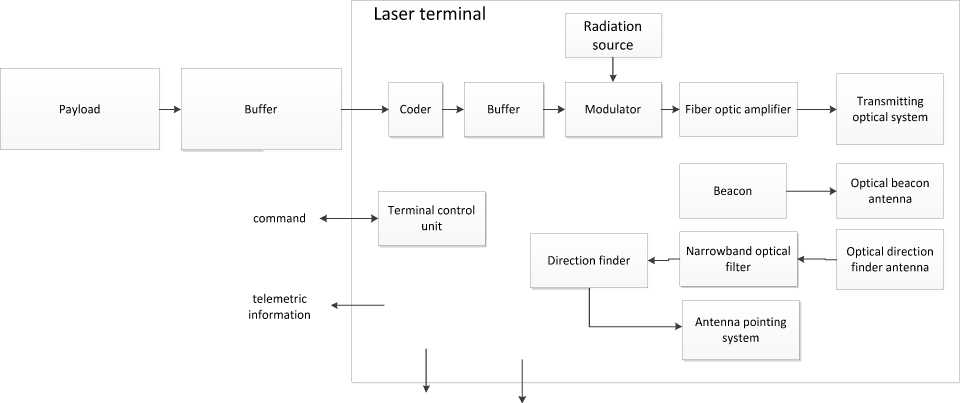
In the mutual tracking mode, the LOS laser terminal starts transmitting the TI via the transmitting optical system at a wavelength of 1.55 μm.
At the RS, the optical signal is fed to the avalanche photodetector, then data processing takes place, the useful signal is extracted and formed for delivering to the ground station (GS) in a radiofrequency range. The schematic block diagram of the LOS laser terminal is presented in fig. 2.
The presented parameters of the communication link (table) are calculated for the case when the LOS moves in a sun-synchronous orbit of 700 km in altitude, and the RS is at an altitude of 35.786 km.
Below there are the calculated formulas of the communication channel of LOS – RS.
The power supplied to the receiver is calculated by formula (1) [10]:
Р rec = P tr G tr G rec L weak L sist ,
where Ptr is the transmitter power, Grec is the effective gain of the receiving antenna, Gtr is the effective gain of the transmitting antenna, Lweak is the signal attenuation coefficient in free space, Lsist is the path loss of the transmitting and receiving equipment.
The diagram of the radiation power and the power supplied at the receiver input (taking into account the attenuation of the communication link) is presented in fig. 3
The effective gain of the receiving antenna is calculated by formula (2) and depends on the wavelength, and the diameter of the receiving telescope [10]:
G rec

where λ is the wavelength, D is diameter of the receiving telescope.
The effective gain of the transmitting antenna:
G tr = 72 , (3)
и
where θ is the width of the angular pattern.
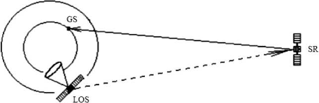
GS - ground station
LOS - low-orbit spacecraft
SR - satellite-repeater
-
Fig. 1. Schematic block diagram of a transmission channel
Рис. 1. Структурная схема канала передачи
digital exchange interface
power source
-
Fig. 2. Schematic block diagram of the LOS laser terminal
Рис. 2. Структурная схема лазерного терминала НКА
Channel parameters of low-orbit spacecraft – repeater satellite
|
Parameters |
Designation |
Value |
Units |
|
Wavelength |
λ |
1.55 |
um |
|
Transmitting antenna diameter |
D tr |
0.05 |
m |
|
Receiving antenna diameter |
D rec |
0.25 |
m |
|
Link length of LOS-RS |
R |
35086 – 41000 |
km |
|
Transmitter power |
P tr |
3 |
dbw |
|
Radiation power at the receiver |
rec |
–79.8 |
dbw |
|
Effective gain of transmitting antenna |
G tr |
114.4 |
w |
|
Effective gain of receiving antenna |
G rec |
105.5 |
db |
|
Attenuation caused by link length |
Lweak |
–289.08/ –290.4 |
db |
|
Path loss of receiver, transmitter |
L sist |
5 |
db |
|
Receiver bandwidth |
dF |
200 |
MHz |
|
Angular pattern width |
θ |
6.18 |
sec |
|
Noise power equivalent |
NEP |
–86.4 |
db |
|
NEP |
M |
6.6 |
db |
|
Number of photons studied in 1 sec |
N stud |
3.89∙1018 |
amount |
|
Number of photons arriving at the receiver in 1 sec |
N rec |
1.09∙1011/ 8.04∙1010 |
amount |
|
Number of photons in 1 bit |
N |
549.5/402.4 |
amount |
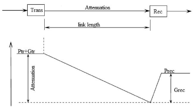
Fig. 3. Diagram representing a communication channel
Рис. 3. Диаграмма представления канала связи
Attenuation in free space depends only on the length of the link [10]:
The number of photons received during the time t is calculated as follows [10]:
L weak

p -t rec
N rec = 7 г , h ■ f
where R is the length of the communication link.
For a complete analysis of the system, we calculate the number of photons emitted by the transmitter and received by the receiver per unit of time.
The number of emitted photons is calculated by formula (5) [10]:
A
Nbm ~ „ ’
E
where A = P tr ∙ t , t is time, E is a quantum energy, calculated by formula (6) [10]:
E = T , (6)
Л
where h is Planck's constant ( h = 6,63∙10-34 J∙с), c is the speed of light ( с = 3∙108 m/s).
where f is a radiation frequency.
Since the relative velocity of a low-orbit spacecraft and a geostationary spacecraft can reach 8 ∙ 103 m/s, and the distance between them is 3.086 ∙ 107 m, it becomes necessary to take into account such effects as light aberration and the Doppler effect [11; 12].
Light aberration. Light aberration refers to the difference in a visible direction of a light source from the real direction to it which is caused by the finiteness of light speed [13]. Let us consider fig. 4, which shows the exchange of signals by LOS and RS. Suppose, at time A , the LOS emits a signal in the direction of the RS. At time B , when the RS receives a signal from the LOS, the latter will have time to move some distance l , and at time B , when the signal from the RS reaches the LOS orbit, it will have time to move from position A to 2 l . In order to “get”
into the LOS, the RS must send a response at a certain angle θ with respect to the direction of the received signal. The angle θ can be calculated as:
where R is the distance between the LOS and RS at time B .
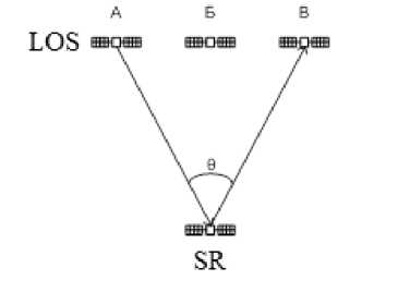
Fig. 4. Aberration of the speed of light
Рис. 4. Аберрация скорости света
When the LOS is moving along a sun-synchronous orbit, its relative speed can be estimated from above as 8 km/s, and the angle which the transmitting antenna of the RS should be deflected at, relative to the visible direction to the LOS, is 11 arc/s. To account for this effect, it is necessary to install a high-speed corrector for light aberration, which is an additional device.
Doppler effect
Let us consider the longitudinal “linear” Doppler effect as the strongest [14; 15], which is described by formula (9):
where v׳ and v are radiation frequencies in fixed and moving coordinate systems, V is the velocity of a mutual motion of the coordinate systems, c is the speed of light.
The change in wavelength caused by the longitudinal Doppler effect can be written as:
АХ = с - с. (10) v v‘
For an optical channel using a wavelength of 1.55 μm, the calculated change in wavelength caused by the Doppler effect was 0.04 nm.
Conclusion. The considered two-level communication system will provide greater carrier capacity, with less power consumption, dimensional specifications and weight of the transceiver equipment, than the radiofrequency range systems being currently in use. The application of this system will allow solving problems, including in the interests of any departments and structures of the Ministry of Defense of the Russian Federation, for which the rate of obtaining information is one of the basic requirements for a satellite communication system.
The communication channel of LOS – RS is a homogeneous medium, where signal attenuation is determined by the length of the communication link in the process of propagation.
However, there is a number of technical problems which have to be solved for the implementation of laser communication channels between LOS and RS:
– high guidance accuracy, mutual tracking at long distances and at space velocities of carriers are necessary;
– electrooptical equipment is becoming more complex: precision optics, micrometrical mechanics, semiconductor and fiber lasers, highly sensitive receivers.
The following conditions are to be considered as well:
– the influence of solar illumination, resulting from exposure of sun beams directly into the viewing sector of the optical receiver;
– ensuring the thermal mode of antennas.
References Inter-satellite optical communication link
- Maral G. Satellite communication system. John Wiley & Sons Ltd, Publication, 2009, 743 р.
- Atrohov A. Yu. [Problems of remote sensing of the earth by modern radar methods]. XXXVI mezhdunarodnaya nauchno-prakticheskaya konferentsiya “Nauchnoe soobshchestvo studentov XXI stoletiya. Tekhnicheskie nauki” [XXXVI International Scientific and Practical Conference “Scientific community of students of the XXI century. Technical Sciences]. Novosibirsk, 2015, No. 9 (35), P. 168 (In Russ.).
- Akimov A., Terekhov S., Danilov D., Shevchuk D. [Prospects for increasing the frequency of observation by space remote sensing Systems]. Tekhnologii i sredstva svyazi. 2016, No. 6 (117), P. 85–91 (In Russ.).
- Heine F., Troendle D. Heine F. Progressing towards an operational optical data relay service. Free-Space Laser Communication and Atmospheric Propagation XXIX, 2017. P. 7.
- Glindemann A., Hippler S. Adaptive optics on large telescopes. Germany, Heidelberg, 1999, 44 p.
- Zuev V. E. Rasprostranenie lazernogo izlucheniya v atmosfere [Propagation of laser radiation in the atmosphere]. Moscow, Radio i Svyaz' Publ., 1981, 288 p.
- Henniger H., Wilfert O. An introduction to freespace optical communications. Germany, Wessling, 2010, 10 p.
- Sodnik Z., Sans M. Extending EDRS to Laser Communication from Space to Ground. Proc. International Conference on Space Optical Systems and Applications (ICSOS), 2012, October 9–12 P. 6.
- Maini A., Agrawal V. Satellite Technology. John Wiley & Sons Ltd, Publication. 2011, P. 696.
- Wilfert O., Kolka Z. Statistical model on freespace optical data link. Proceedings of SPIE. 2004, Vol. 5550, P. 203.
- Vasilenko A. V., Kashkin V. B. [Evaluation of the influence of astronomical refraction on an optical satellite link]. Zhurnal Sibirskogo federal'nogo universiteta. Inzheneriya i tekhnologiya. 2012, Vol. 5, No. 3, P. 353–357 (In Russ.).
- Aleksandrov A. V., Melnikov P. V., Tverdochlebov S. S., Reshetnikov S. Yu., Milko D. S. [Protected satellite communication model based on System Vue]. Nauchnaya sessiya TUSUR [Scientific session TUSUR]. Tomsk, 2015, P. 60–62 (In Russ.).
- Caplan D. Laser communication transmitter and receiver design. Journal Optical and fiber communication report. 2007, P. 138.
- Roddy D. Satellite communication, Prentice-Hall Inc., Publication, 1989, P. 656.
- Heine F., Troendle D. Progressing towards an operational optical data relay service. Free-Space Laser Communication and Atmospheric Propagation XXIX, 2017. P. 7.
