Intravascular Ultrasound Image Segmentation Using Morphological Snakes
Автор: Mrabti Mohamed Amine, Hamdi Mohamed Ali
Журнал: International Journal of Image, Graphics and Signal Processing(IJIGSP) @ijigsp
Статья в выпуске: 5 vol.4, 2012 года.
Бесплатный доступ
From the first use of the technics of intravascular ultrasound (IVUS) as an imaging technique for the coronary artery system at the 70th century until now , the segmentation of the arterial wall boundaries still an important problem . Much research has been done to give better segmentation result for better diagnostics , evaluation and therapy planning. In this paper we present a new segmentation technics based on Morphological Snakes which developed by Luis Álvarez used for the first time for IVUS segmentation. It is a simple , fast and stable approach of snakes evolution algorithm. Results are presented and discussed in order to demonstrate the effectiveness of this approach in IVUS segmentation.
IVUS Segmentation, Morphological Snakes, Contours detection, LabVIEW
Короткий адрес: https://sciup.org/15012302
IDR: 15012302
Текст научной статьи Intravascular Ultrasound Image Segmentation Using Morphological Snakes
Published Online June 2012 in MECS
-
I. Introduction
From its upturn in the 1970s [1,2], Intra Vascular Ultra Sound (IVUS ) has become a treasured technique for the treatment and diagnosis of coronary artery diseases [3] . Intra Vascular Ultra Sound (IVUS ) is a catheter-based system that offers detailed and accurate measurements and information of lumen like vessel size ,plaque size and location.All these information are given in 2D image format .From this image, we distingue three regions: the lumen, the vessel wall, consisting of the adventitia and the intima layers and the media plus surroundings [4,5] . Studies have revealed the advantage of IVUS in applications where accurate visualization and quantification of atherosclerotic plaques is required [6 – 9] , such as evaluating stent deployment or plaque progression – regression studies of lipid-lowering medical therapy .
Despite the good vulnerability determination, IVUS has the disadvantage that manual analysis of the huge amount of images isdifficult, subjective, and time-consuming .Consequently, there is a big interest for the development of automaticsegmentation technics for IVUS images .This present a challenge due to the noise and image quality .
Much of research on this question has been done using different technics and algorithms like active contours , shape-driven , go snakes , live wire…[ 10-16]. In this study, a new snake formulation, the so-called Morphological snake [17], is employed to detect Lumen and Media /Adventitia contours . We used this new snake in a traditional segmentation pipeline : first , the preprocessing of the image , then , catheter circle detection and finally Snakes initialization . Those themes are presented in the following order 2.preprocesing , 3segmentation and 4 results .
-
II. Theory Of Morphological Snakes
Many technics were used like level set, active snakes, live wire …[ 10-16] to detect the mediaadventitia contour .In our case we propose a solution based on morphological snake.
This algorithm developed by Alvarez and his colleagues uses a morphological discretization of the Partial Differential Equations of curve evolution of the geodesic active contours in a level set framework . The main steps of this algorithm are:(1) the contour is represented in an implicit form included as the level set of an embedding function calculating the contour signed distance function. (2) Solving the Partial Differential Equations in a contour narrow ban. .(3) Keeping the stability of the algorithm by reinitializing of the distance function and the contour [17].
Let C a parameterized 2D curve ; C : [0,1] ->R2 and I an image I :R2 ^ R . Under the effect of the scalar field F the curve is deformed along its inwards normal vector , in other word Ct=N.F .
In the geodesic active contours [21] :F is approached by:
F=g(I)k+g(I) ν - ∇ g(I).N ,with k is euclidian curvature ,ν is a real parameter of the balloon force term [22] and g(I) is a function low at the boundaries of image and selects the region which will attract the contour , In general g(I) is defined by :
()= √ |∇ ∗ | (1)
At the boundaries of the image :
()=| ∗ | (2)
We define u as an implicit representation of C
u: R + xR 2 ^ R , C(t)= {(x, y); u(t, (x, y)) = 0}.
As illustrated previously , the curve evolution has the form C t =N.F so we can see that the evolution of any function u(x,y) embeds the curve such as one of its level set is :
= |∇ | (3)
at
The curvature parameter K is calculated with the information on u :k=div( ∇ ).Arranging all those equations , the geodesic active contours in a level set frame work became :
= ()| ∇ |( (∇ )+ )+ ∇ ( ) ∇ (4)
| ∇ |
The solution of the previous equation can be spitted into in 3 terms : (1) the Balloon force term, (2) the smoothing term and (3) the attraction force term and we will explore those elements separately
-
A. The Balloon force term
The two known morphological operators erosion and dilatation defined respectively (E h u)(x)=sup yϵ hb u(x-y) and (Dhu)(x)=inf yϵhb u(x-y) with h is the operator radius , b is a disk with radius 1. In terms of morphology continues scale , the defined function u d (t,x)=D t u 0 (x) is the solution of the PDE :
=| ∇ | (5)
With ud(0,x)= u0(x) , We can deduce that Dh is the infinitesimal generator of the partial differential equation proved by lim →
D h u-u =|∇ u |
h
With an analogous reasoning, we can say that u e (t,x)=E t u 0 (x ) is the solution of the PDE :
=-|∇u| (7)
du , , = ( ) | ∇ | (8)
The strength of each segment of the curve is controlled by g(I) which acts as weight factor :when g(I) increase , the corresponding segment moves away from target zone and the balloon force should be strong , otherwise ,if g(I) decrease , the corresponding segment approaches from its target and balloon force becomes neglected. In effect, according with the sign and value ofν the remaining term (ν |∇u|) bring us to the dilatation and erosion PDEs given above. At n iteration , the balloon force PDE applied over un may be using the morphologic approach [17]:
( )( ) ()( )>
( )={( )( ) ()( )>
( )( ) ℎ
With Ed and Dd are the discrete forms of dilation and erosion. The structure element is formed with eight neighbors of the pixel. Ed and Dd are executed by iterations of 8 or 5 neighborhood minima (or maxima) computation with homogeneous Neumann type borders condition . In our case we used the 5 neighbors version. Additional advantageous option to make evolves this Balloon force term is to use an image interval value :
[ 17-20]
( )=
{
( )( ) ( ) ∈ [ , ]> v >0
( )( ) ( ) ∈ [ , > v <0
( )( ) ℎ
-
B. The smoothing term
Let B a set of all line segments with length of 2 centered at the origin of R2. We define the morphological line operators as:
S^B y€=+^S
(JSdu )(x) = inf sup u(;y)
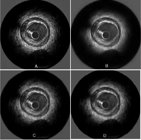
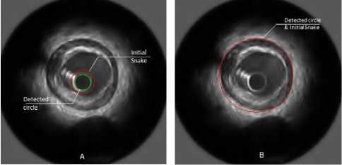
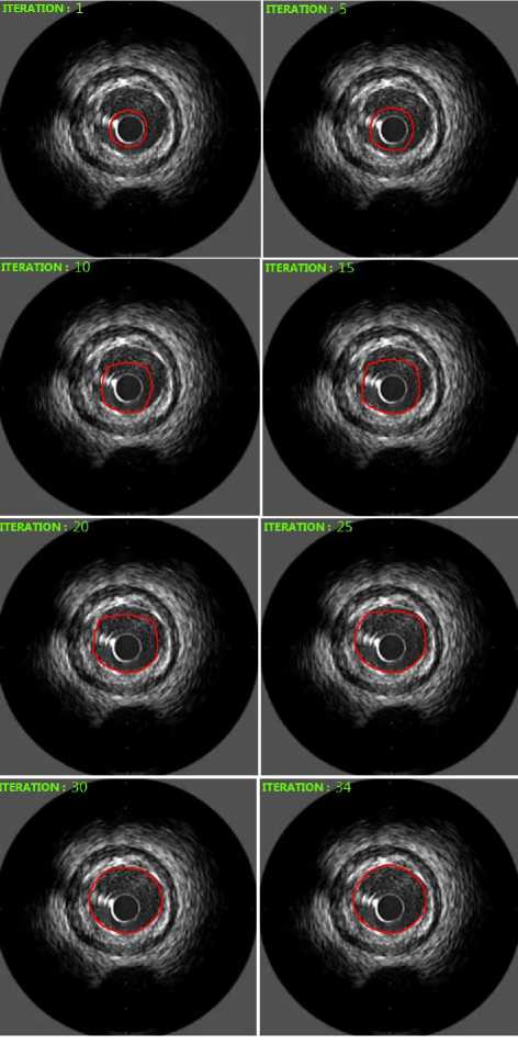
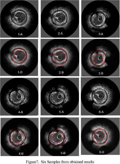
■^^^ y The mean operator is : ( )() ( )( ) ( )()= The called Koepfler -Catté-Dibos- scheme [17] relates the operator Ft with the meancurvature motion in the following way: ( )( )= ( )+ℎ |∇ | .∇/()+ (ℎ ) We get the infinitesimal generator of theFh operator by reorganizing terms and setting a smallh ( √ ( ) ( ) =|∇u |div(|∇∇ |)(x) (14) lim → h Consequently, we can solve the mean curvature motion by means of the Fh operator. But unluckily, we can see that Fh is no longer a morphological operator in the sense that it engenders new level set values. We can resolve this issue using operator composition . For a small h we define two operators and + / / ≈ and their infinitesimal operators and the first order approximation of gives ≈ ( +ℎℎ1( )) +ℎℎ1( )+ ℎ2ℎ( )( +ℎℎ1) TuoThU 2 2 ℎℎℎ ≈ + ℎ( ) + ℎ( ) + ( ) ℎ ℎ( ) We can neglect the last term the equation give us : ( )( ) ~+ - - 22 so the non-morphological operator F can be replace by which will be iterate to approach to the solution of : = ( )|∇ | (∇ ) | | And g(I) is a weight factor which controls the strength of the smoothing operation at each point . By discretizing it another time by means of a threshold t2the above PDE can be approached by using these line morphological operators in this numerical scheme (approximates mean curvature motion) : ( )( ) ( ) ≥ (17) () ℎ ={ With SId and ISd are discrete forms of the aloft morphological continuous line operators. Both SIdand ISd have their specific form of the set B, P, which is a group of four discretized segments centered at the origin: / Fo = {(0.0).(1.0).(—1. 0)} \ P1 = {(O:O):(O:1):(O,-1)} F2 = {(O:O):(L1):H:-1)} Vf3 = {(0:0):(L-1):(-L1)}/ In a binary image u , the SId operator affects only active (white) pixels unlike the ISdwhich works only with inactive(black) pixels .Suppose that u(x0) is a black pixel , in other term u(xo)=0.Then infyϵxoPu(y) will be set to 0 for every segment P in P , so (SId u)(xo)=0. Now , for a white pixel x1 , from this pixel and along 3 pixels , theSIdoperator seeks for straight lines in four possible directions corresponding to the segments ofP .If no straight line find , the pixel is transformed inactive (figure 2) . The combination SId o ISd give us a new morphologic operator which removes the sharp black pixels with ISdand theSIdremoves the sharp white ones(figure 4). We find here some illustrations of the effect of the SIdand ISdoperator on separated pixels of binary images. In first case, if a straight line is found (striking in red), the central pixel remainswhite (a) and (b). In second case , if the central pixel does not fit into a straight line of white pixels, it is became black(c) and (d). For clarification purposes, we take the pixels on the boundaries are not affected by the operator[17-20]. (a) (6) (c) (d) Figure1. Some illustrations of the effect of the SId . In those examples where as straight line is found ( striking in red) , the central pixel remains white ((a)and(b)). When the central pixel don’t belong to a straight line of white pixels , it is made inactive ((c)and(d)) . Figure2. Examples of the ISd operator Figure3. Examples of the ISd o SIdoperator III. Algorithm Implementation A. Preprocessing IVUS images are quite noisy, so to perform the segmentation in an easier way, denoising it is a necessary step to apply filters [24]. Many different types of filters where tested: median filter, Gaussian filter and wavelet transform. Finally we have choose a wavelet transform based filter which gave the best result [23] 1 if Vu"+^Vg(I)(x)>0 u"+^ = 0 if Vu"+^Vg(I)(x) < 0 (un+l if Vu"+^Vg(I)fx) = 0 u‘ SIdo ISd un+1) (x)if g(I)(x)> t2 u"+3 (x) o tieerw ise Figure4. An example of filtered image with three different low pass filters: (A)Original image . (B) Denoised image by using wavelet. (C) Gauss filter. (D) Median filter Which represent the morphological implementation of the PDE. Just a reminder, the input and the output level set is a binary image in other words; these 3 numerical systems are morphological that they don’t make extra level set values, [17-20]. The snake is initialized automatically by detecting the catheter circle which detected by using Hough transform. Figure 5. Snakes initialization .(A) Detection of the catheter circle ( green) and the initial position ofthe Lumen (red)contour snake .(B) Initial position of the Media/Adventitia contour (red) B. Implemantation As explained above, the active contour equation (4) is made up of three different components: a smoothing force, a balloon force and an attraction force. And these components may be solved with morphological operators, so the algorithm is very easy, in each iteration we will apply the morphological smoothing, the morphological balloon force and the discretized attraction over the embedded level-set function u . At n iteration, let un R2^{0,1} and un+1 from un using the following schemes : (Ddu")(x) if |v|y(I)(x) > tt and. v > 0 (Edu")(x')if |v|y(I)(x) > tt add v < 0 a"+l (x) = J (it")(x) о tierrw ise From this circle, a binary level-set image is build u(x) allocating the value 0 outside the contour and 1 inside .For t1 and t2 in expressions (20) and (22) we fit t1 and t2to 0. That is, we provide a number 0 < p< 1 and we take t1such that: |{xen :д(1)(х)>^ }| (22) -------№i-------= p The figure 6 shows the snake evolution at different iteration: Figure6.Morphological active contours on IVUS image For the 50 tested IVUS images, the paired difference between our method and observer, we found a mean difference of -0,04±0,47mm2 for the vessel, and 06±0,26mm2 for the lumen cross-sectional areas TABLE1. Area differences between the automatic segmentation and the manual expert segmentation for Lumen and Media/Adventitia contours . Area Difference (mm2) Lumen Contours 0,06±0,26 Media/Adventitia contours -0,04±0,47 C. Result The mentioned algorithm was tested by using LabVIEW with 50 IVUS images were acquired with a 20 MHz mechanical catheter using motorized pullback (1mm/s) .Image size was 356 X 356 , those images were analyzed by one experienced observer. The observer used a semi-automatic segmentation method to obtain lumen and vessel contours which were then manually corrected where necessary. No images were excluded and differentconfigurations with calcified plaque, shadows, sidebranches, and drop-out regions were present. The pixel size is 27 x 27 µm2 . The following figure shows our results for serval images: In addition, linear regression analysis revealed that the obtained result was strongly correlated with the reference manual, and yielded the following results for Lumen and Media / adventitia contours respectively :y = 0 .944x + .0278 ,r = 0 .9; y = 0 .616x +2.564 ,r = 0 .78 . As shown, the performance of the automated segmentation was remarkably high, even in poor quality IVUS images due to artifacts, calcifications, or speckles noise, additional supporting the detection efficiency of our segmentation approach. With respect to the manual segmentation method, the required analysis time for the dataset of 50 selected images reduced by 98% with our method (2 s per image for morphological snakes versus 105 s per image for manual segmentation), suggesting that apart from applicable and reliable, and the method we propose is markedly rapid. Figure7. Histogram indicating the error surface .(A) for Lumen contours .(B) For Media/Adventitia contours Figure 8 : Linear regression plots of the differences between automated and manual segmentation .(A) Lumen area (mm2). (B) Vessel area (mm2) IV. Conclusions And Prospects In this paper we have presented a new approach for IVUS segmentation based on morphological snakes. The new approach has been applied to IVUS images which were segmented; Lumen and Adventitia /Media contours were detected automatically and compared with expert-corrected contours. Results show good correlation between agents and observer for the lumen areas with r =0.9, and good correlation for the vessel areas with r =0.78. In future, we plan to focus on detecting calcifications and branch openings. We will also take advantage of the continuity of images in the IVUS pullback sequences and enhance our algorithm by extending it to 3D. Acknowledgment We thank anonymous referees for their constructive comments. This research is supported by National Institute of Applied Sciences and Technology of Tunis




Список литературы Intravascular Ultrasound Image Segmentation Using Morphological Snakes
- Lee JT, White RA. Basics of intravascular ultrasound: an essential tool for the endovascular surgeon. Sem Vasc Surg 2004;17(2):110–8.
- Klingensmith JD, Shekhar R, Vince DG. Evaluation of three-dimensional segmentation algorithms for the identification of luminal andmedial–adventitia borders in intravascular ultrasound images. IEEE Trans Med Imaging 2000;19(10).
- Nissen SE, Yock P. Intravascular ultrasound: Novel pathophysiological insights and current clinical applications. Circulation 2001;103: 604–616
- Mintz G, Nissen S, Anderson W, Bailey S, Erbel R, Fitzgerald P, Pinto F, Rosenfield K, Siegel R, Tuzcu E, Yock P. American College of Cardiology Clinical Expert Consensus Document on Standards for Acquisition, Measurement and Reporting of Intravascular Ultra-sound Studies (IVUS). A report of the American College of Car-diology Task Force on Clinical Expert Consensus Documents. J Am Coll Cardiol 2001;37:1478 –1492.
- Nissen SE. Shortcomings of coronary angiography and their implications in clinical practice. Clevel Clin J Med 1999;66(8): 479 – 85
- Mintz GS, Painter JA, Pichard AD, Kent KM, Satler LF, Popma JJ, Chuang YC, Bucher TA, Sokolowicz LE, Leon MB. Atherosclerosis in angiographically normal coronary artery reference segments: an intravascular ultrasound study with clinical correlations. J Am Coll Cardiol 1995;25(7):1479 – 85.
- Tuzcu EM, Berkalp B, De Franco AC, Ellis SG, Goormastic M, Whitlow PL, Franco I, Raymond RE, Nissen SE. The dilemma of diagnosing coronary calcification: angiography versus intravascular ultrasound. J Am Coll Cardiol 1996;27(4):832 – 8.
- Hausmann D, Johnson JA, Sudhir K, Mullen WL, Friedrich G, Fitzgerald PJ, Chou TM, Ports TA, Kane JP, Malloy MJ, Yock PG. Angiographically silent atherosclerosis detected by intravascular ultrasound in patients with familial hypercholesterolemia and familial combined hyperlipidemia: correlation with high density lipoproteins. J Am Coll Cardiol 1996;27(7):1562 – 70.
- Hoffmann R, Mintz GS, Popma JJ, Satler LF, Kent KM, Pichard AD, Leon MB. Overestimation of acute lumen gain and late lumen loss by quantitative coronary angiography (compared with intravascular ultrasound) in stented lesions. Am J Cardiol 1997;80(10):1277 – 81.
- Moraes, M.C . An automatic media-adventitia border segmentation approach for IVUS images . IEEE Computing in Cardiology. 2010 .p 389 - 392
- Unal, G. Bucher, S. ; Carlier, S. ; Slabaugh, G. ; Tong Fang ; Tanaka, K. . Shape-Driven Segmentation of the Arterial Wall in Intravascular Ultrasound Images. Information Technology in Biomedicine, IEEE Transactions on .2008. p 335 – 347
- Katouzian, A. Angelini, E. ; Carlier, S. ; Suri, J. ; Navab, N. ; Laine, A. .A State of The Art Review on Segmentation Algorithms in Intravascular Ultrasound (IVUS) Images . Information Technology in Biomedicine, IEEE Transactions on .2012 Feb .p1
- Cardinal MHR, Meunier J, Soulez G, Maurice R, Therasse E, Cloutier G. "Intravascular Ultrasound Image Segmentation: A Three-Dimensional Fast-Marching Method Based on Gray Level Distributions" IEEE Trans. Med. Imag. 2006 May;vol.25(5):590–601.
- Giannoglou GD, Chatzizisis YS, Koutkias V, Kompatsiaris I, Papadogiorgaki M, Mezaris V, Parissi E, Diamantopoulos P, Strintzis MG, Maglaveras N, Parcharidis GE, Louridas GE. "A novel active contour model for fully automated segmentation of intravascular ultrasound images: In vivovalidation in human coronary arteries" Computers Biol. Med. 2007 Sep;37:1292–1302.
- Brusseau E, de Korte C, Mastik F, Schaar J, van der Steen A. "Fully automatic luminal contour segmentation in intracoronary ultrasound imaging - A statistical approach" IEEE Trans. Med. Imag.2004;vol.23:554–566.
- Giannoglou GD, Chatzizisis YS, Sianos G, Tsikaderis D, Matakos A, Koutkias P, Diamantopoulos N, Maglaveras GE, Parcharidis GE, Louridas V. "In-vivo validation of spatially correct three-dimensional reconstruction of human coronary arteries by integrating intravascular ultrasound and biplane angiography" Coron Artery Dis. 2006;vol.17(6):533–43.
- L. Alvarez, L. Baumela, P. Marquez-Neila and P. Henriquez. "Morphological Snakes", CVPR 2010, San Francisco, U.S.Ahttp://www.sciweavers.org/publications/morphological-snakes
- V. Caselles, R. Kimmel, and G. Sapiro. "Geodesic active contours", International Journal of Computer Vision, 22(1):61–79, 1997.
- [F. Catté, F. Dibos, and G. Koepfler. "A morphological scheme for mean curvature motion and applications to anisotropic diffusion and motion of level sets", SIAM Journal on Numerical Analysis, 32(6):1895–1909, 1995.
- F. Guichard, J.Morel, and R.Ryan. "Contrast invariant image analysis and PDE's". http://mw.cmla.ens-cachan.fr/~morel/JMMBookOct04.pdf.
- R. Goldenberg, R. Kimmel, E. Rivlin, and M. Rudzsky. Fast geodesic active contours .IEEE Transactions on Image Processing, 10( 10) :1467–1475, 2001.
- V. Caselles , R. Kimmel, and G. Sapiro. Geodesic active contours . International Journal of Computer Vision, 22( 1) :61–79, 1997
- M.A. Hamdi "A Comparative Study in Wavelets, Curvelets and Contourlets as Denoising Biomedical Images" International Journal of Image, Graphics and Signal Processing Year: 2012 Vol: 4 Issue: 1 Pages / record No. 44-50
- M.A. Hamdi "Combining an alternating sequential filter (ASF) and curvelet for denoising coronal MRI images " Contemporary Engineering Sciences, Vol. 5, 2012, no. 1-4, 85-90.

