Investigation of the stress state and assessment of the stability of an anisogrid cylindrical shell when changing the parameters of the rib structure under static loading

Author: Kovalchuk L.M., Burnysheva T.V.
Journal: Siberian Aerospace Journal @vestnik-sibsau-en
Section: Aviation and spacecraft engineering
Article in issue: 1 vol.23, 2022.
Free access
The object of the study is a cylindrical mesh shell without a regular structure covering, made of carbon fiber composite material. A distinctive feature of this class of structures is the intersection of families of annular and spiral ribs. Mesh shells are used as power elements of spacecraft, therefore, when designing them, the main re-quirements are a reduction in the mass of the structure, high strength and stiffness characteristics. The re-duction of the shell mass is achieved by varying and selecting the structural and geometric parameters of the ribs. The article considers a set of mesh cylindrical structures of fixed mass. The authors have developed and presented an algorithm for calculating the number of elements of a regular rib structure and calculating the values of geometric parameters of elements of rib families. Two approaches to the formation of rib sys-tems are considered: by changing the heights or thicknesses of the rib structure. A macro has been developed for modeling parametric discrete models of such rib structures in the An-sys Mechanical APD software package. When constructing discrete grid models, a one-dimensional two-node finite element BEAM4 was used. The model was rigidly attached at the nodes along the lower edge, a load was applied to the nodes of the upper edge. Two types of loading were considered. The “non-flight” mode was determined by the axial loading of the shell evenly distributed along the upper edge. Flight mode – additionally took into account the applied moment. The displacement and deformation fields were calculated numerically in the ANSYS finite element package. The article presents the results of a study of the effect of the density of the rib structure on the stability of mesh shells under static axial loading, natural frequencies and waveforms. It is shown that with increasing density, the rib structure becomes thinner. At the same time, the critical load decreases, the values of the natural frequencies of the shells decrease, and the number of waves in the forms increases. The influence of approaches to the modeling of rib structures on the results of numerical calculations is noted.
Mesh shell, ANSYS Mechanical APDL, stress-strain state, finite element method, stability, eigen forms, computational experiment
Short address: https://sciup.org/148329610
IDR: 148329610 | UDC: 519.85 | DOI: 10.31772/2712-8970-2022-23-1-81-92
Text of the scientific article Investigation of the stress state and assessment of the stability of an anisogrid cylindrical shell when changing the parameters of the rib structure under static loading
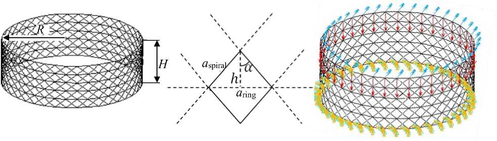
Mesh cylindrical composite shells consisting of the intersection of spiral and annular ribs (Fig. 1, a ) often act as elements of aircraft aggregates [1; 2]. In spacecraft, mesh shells act as power housings, adapters. Shells of this class have high rigidity, strength characteristics and weight efficiency [3]. At the same time, the design of the rib structure of a specific mesh shell, which provides the necessary reliability of the structure with its minimum weight, remains an urgent task.
The article discusses two approaches to the formation of regular rib structures of mesh shells without sheaths with a fixed mass. The results of numerical calculations of the stress-strain state of a series of shells under static axial loading, the results of the analysis of the stability of structures, natural frequencies and vibration patterns of shells are presented.
Algorithm for calculating the values of geometric and structural parameters of mesh ribs of shells without covering with a given mass
The first stage of the algorithm includes the calculation of the mass of the basic structure.
Figure 1, a shows a discrete model of the initial mesh shell, which includes
80 pairs of spiral ribs and 6 annular ribs. Above and below the shell is reinforced with frames.
а б
Рис. 1. Дискретная модель сетчатой оболочки регулярной структуры:
а – геометрические параметры сетки;
б – схема приложения нагрузки «полет» и закрепление узлов нижнего шпангоута
Fig. 1. Discrete model of the mesh shell of a regular structure: a - geometric parameters of the mesh;
b - the scheme of application of the load "flight" and fixing the nodes of the lower frame
Consider an elementary rhombic cell (Fig. 1, a ). Since the tetragonal structure tends to the correct shape, we will consider the cell equilateral. Denote by a спир – the length of the side of the unit cell, by a кол – the length of the diagonal located along the annular rib. Calculating the number of elements included in the annular and spiral ribs and determining the total number of elements for each of the families of ribs allows you to determine the mass of the shell. The mass of the structure is calculated taking into account the families of ribs
M = n1 · mспир + n2 · mкол + n3· mшп, where n 1, n 2, n 3 is the number of structural elements in the families of spiral, annular ribs and frames; m спир is the mass per element of the spiral rib; m кол is the mass per element of the annular rib; m шп is the mass per element of the frame. To do this, the values of the density of the materialp, the angle between the spiral rib and the generatrixa, the height H and the radius R of the structure are entered.
The block diagram for calculating the mass of the initial structure is shown in Fig. 2 (stage 1).
The second stage of the algorithm allows you to calculate the values of geometric and structural parameters of the meshes, which are obtained by modifying the original shell structure.
The number of /annular ribs m is determined by the formula m = H / h = ( H • Nкол) / (4-n-R • cos (a)), where N спир is the number of elements in the family of spiral ribs; h is half the height of the rhombic cell.
Based on the fact that the triangle formed by the ribs is isosceles, the length of the element of the annular and spiral ribs will be calculated using the following formulas:
a спир
a шп
= L / (Nкол/2) = ( 4-п-R) / Nкол, = L /(Nкол/2) = ( 4-п-R)/ Nшп, where is the circumference L = 2 - n • R.
We express the volume and mass of the structural element of each rib family in terms of their geometric parameters. So for an element of a spiral edge , the following is true:
V „ — a -b • h „.
спир спир спир спир , спир спир p, where hспир is the height and bспир is
the thickness of the spiral rib element.
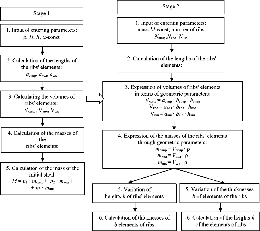
Fig. 2. Block diagram of the algorithm for calculating the values of geometric and structural parameters of the mesh ribs of shells without covering with a constant mass
Рис. 2. Блок-схема алгоритма вычисления значений геометрических и структурных параметров сеток ребер оболочек без обшивки с неизменной массой
Knowing the fixed mass of the structure and its fractional distribution between the three families of ribs, we have the ability to change the density of the rib structure of the shell by varying the values of the heights or thicknesses of the ribs. In the tables 1 and 2 are the indicators of five rib structures of shells obtained by varying different indicators.
The presented structures were implemented as discrete models in the Ansys Mechanical APDL software package.
Table 1 Parameters of the structure of mesh shells when varying the thickness of the ribs
|
Model Number of spiral ribs |
1 |
2 |
3 |
4 |
5 |
|
|
80 |
120 |
160 |
240 |
320 |
||
|
Spiral paired |
Length a (mm) |
211 |
141 |
110 |
70.4 |
53 |
|
Height h (mm) |
30 |
|||||
|
Thickness b (mm) |
5 |
4.4 |
2.5 |
1.7 |
1.3 |
|
|
Number of annular ribs |
6 |
9 |
11 |
16 |
21 |
|
|
Annular |
Length a (mm) |
314.2 |
210 |
157 |
104 |
79 |
|
Height h (mm) |
30 |
|||||
|
Thickness b (mm) |
15 |
8.6 |
6.7 |
4.3 |
3.2 |
|
|
Frames |
Length a (mm) |
314.2 |
210 |
157 |
104 |
79 |
|
Height h (mm) |
40 |
|||||
|
Thickness b (mm) |
40 |
|||||
Table 2
Parameters of the structure of mesh shells when varying the heights of the ribs
|
Model Number of spiral ribs |
1 |
2 |
3 |
4 |
5 |
|
|
80 |
120 |
160 |
240 |
320 |
||
|
Spiral paired |
Thickness b (mm) |
5 |
||||
|
Length a (mm) |
211 |
141 |
110 |
70.4 |
53 |
|
|
Height h (mm) |
30 |
18 |
14 |
9.286 |
6.908 |
|
|
Number of annular ribs |
6 |
9 |
11 |
16 |
21 |
|
|
Annular |
Thickness b (mm) |
15 |
||||
|
Length a (mm) |
314.2 |
210 |
157 |
104 |
79 |
|
|
Height h (mm) |
30 |
18 |
14 |
9.286 |
6.908 |
|
|
Frames |
Thickness b (mm) |
40 |
||||
|
Length a (mm) |
314.2 \ |
210 \ |
157 \ |
104 \ |
79 |
|
|
Height h (mm) |
40 |
|||||
Construction of discrete mesh shell models in Ansys Mechanical APDL
A macro containing a parametric discrete model of a cylindrical mesh shell of a regular structure was developed for modeling mesh shell structures in the ANSYS software package [4; 5].
When constructing a discrete model, a one-dimensional two-node finite element BEAM4 [6] with six degrees of freedom at each node was used. Each family of ribs was assigned its own type of crosssection, its own set of variables and constants was set. The model was rigidly attached at the nodes of the lower edge, a load was applied to the nodes of the upper edge.
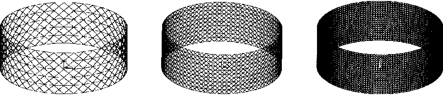
We introduce the density parameter of the rib structure p * . Density refers to the ratio of the surface area of a shell with a discharged mesh to the surface area of a solid shell.
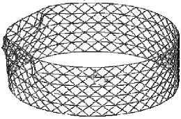
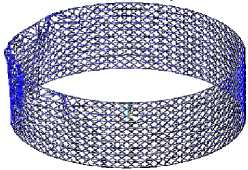
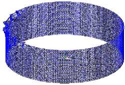
Figure 3 shows discrete models of mesh structures of different densities.
a б в
Fig. 3. Discrete models of mesh structures: а - p* ~ ' p* = 0,15; б - p * = 0,253; в - p * = 0,459
Рис. 3. Дискретные модели сеток: а - p * 3 ' р* = 0,15; б - p * = 0,253; в - p * = 0,459
Two variants of the load F were considered: the "flight" mode included an axial compressive force F = 625 N with a moment M = 80 N · m, distributed along the upper edge of the model; the "non–flight" mode – a compressive axial force F = 625 N, evenly distributed over the nodes of the upper frame.
Stressed state of the mesh shell
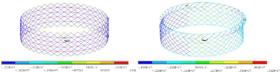
Figure 4 shows the stress fields of the rib structure, density p * = 0.15.
а
б
Fig. 4. Stress fields of the original design with 80 pairs of spiral ribs: а – “non-flight” mode; b – “flight” mode
Рис. 4. Поля напряжений исходной конструкции с 80 парами спиральных ребер: а – режим «не полет»; б – режим «полет»
When the loads described above are applied to the shell, the ribs are deformed: the annular ribs of the structure are stretched, and the spiral ribs are compressed [7].
The influence of the density of the rib structure p*, the height h and the thickness of the ribs b on the stress state of the mesh shell was studied. During the computational experiment, the density of the rib structure p* changed from 0.15 to 0.495, the number of pairs of spiral ribs N from 80 to 320, the thickness b from 15 to 3.2 mm and the height h from 30 to 6.9 mm.
σsmax, b, mm
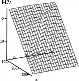
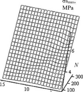
b , mm
а б
Fig. 5. Surfaces of maximum longitudinal stresses σs max in the shell ribs in the “flight” mode from thickness b and the number of pairs of spiral ribs N : a – maximum tensile stresses; b – maximum compressive stresses
Рис. 5. Поверхности максимальных продольных напряжений σs max в ребрах оболочки при режиме «полет» в зависимости от толщины b и числа пар спиральных ребер N : a – максимальные растягивающие напряжения; б – максимальные сжимающие напряжения
Figure 5 above shows the response surfaces of the maximum longitudinal stresses in the spiral and annular ribs of the shell with varying the number of pairs of spiral ribs N and the thickness of the rib structure b . The analysis of the above surfaces shows that the maximum longitudinal stresses linearly depend on the variable parameters; the change in the number of pairs of spiral ribs has a stronger effect.
Figure 6 shows the response surfaces of the maximum longitudinal stresses in the spiral and annular ribs of the shell with varying density of the rib structure p * and the height of the ribs h . The analysis of the surfaces shows that the maximum stresses vary linearly, the change in the density of the rib structure p* has a greater effect.
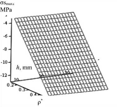
а
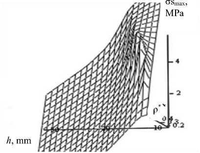
б
Fig. 6. Surfaces of maximum longitudinal stresses σsmax in the shell ribs in the “flight” mode from the height h and the density of the rib structure ρ*: a – maximum tensile stresses; b – maximum compressive stresses
Рис. 6. Поверхности максимальных продольных напряжений σs max в ребрах оболочки при режиме «полет» в зависимости от высоты h и плотности реберной структуры ρ*: а – максимальные растягивающие напряжения; б – максимальные сжимающие напряжения
Analysis of the stability of the mesh shell
An analysis of the above mesh shells for stability was carried out in Ansys Mechanical APDL. The Buckle analysis was used for the study [8; 9], the problem was solved in a linear formulation with the derivation of forms of loss of stability [10]. Fig. 7 shows the values of critical loads F kr and the forms of loss of stability of shells of different densities.
Based on the results of the computational experiment, a graph of the dependence of the critical load on the density of the rib structure p* is constructed (Fig. 8).
N = 80, m = 6, F kr = 1292 N
а
N = 160, m = 11, F kr = 256 N
б
Fig. 7. Forms of loss of stability of rib structures of different densities in the “flight” mode
N = 320, m = 21, F k r = 31 N
в
Рис. 7. Формы потери устойчивости реберных структур различной плотности при режиме «полет»
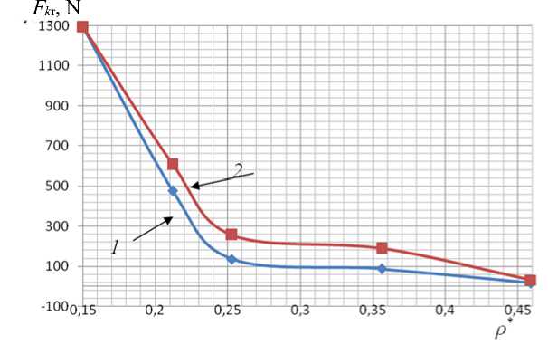
Рис. 8. График зависимости критической нагрузки F кр от плотности реберной структуры ρ*;
1 – варьирование толщины b реберной структуры; 2 – варьирование высоты ребер h
Fig. 8. Graph of the dependence of the critical load of the F kr on the density of the rib structure ρ*; 1 – variation of the thickness b of the rib structure; 2 – variation of the height of the ribs h
The analysis of Fig. 8 showed the following: in the mesh structures obtained by changing the height of the ribs h , when analyzing the stability of the shells, the values of critical loads F are higher than in the rib structures formed by varying the thickness of the ribs b .
In the structures under consideration, with an increase in the number of pairs of spiral ribs, the critical load F kp decreases. This phenomenon can be explained by the fact that with an increase in the density of the rib structure, the shell becomes thinner, since its mass is fixed, therefore, the shell becomes susceptible to critical loads.
Analysis of natural frequencies and waveforms of mesh shells
A study of the mesh shell structure on natural frequencies and waveforms was carried out. MODAL analysis in Ansys Mechanical APDL was used for numerical calculation [11-15].
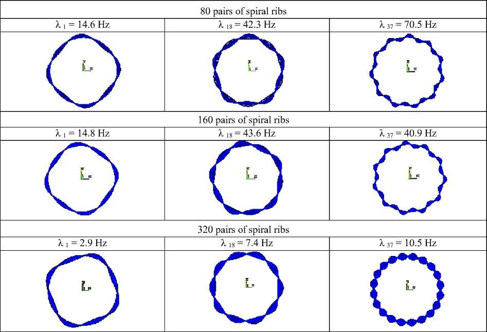
Tables 3, 4 show the eigenvalues and waveforms of shells with different densities of rib structures. As the values of the eigenvalues increase, the number of waves in the structure increases from 8 to 12, and they have a symmetrical structure (Tables 3, 4). This phenomenon is explained by the fact that in the structures there are ribs directed to the right and left with an equal angle of inclination α to the forming shell.
The analysis of frequencies and shell shapes allows us to draw the following conclusions. As the density of the rib structure increases, the shell becomes thinner, and the frequency values decrease. In the mesh structures formed by varying the thicknesses of the ribs b , the values of the natural frequencies are several times greater than the values of the corresponding frequencies in the structures formed by varying the heights of the ribs h .
The numerically obtained values of the natural frequencies of the shells were compared with the values of the frequencies calculated analytically. The method of calculating natural frequencies is given in [16].
The equation of natural frequencies of a mesh cylindrical shell looks the following way:
K1 · ωmn6 – K2 · ωmn4 + K3 · ωmn2 = L, where K 1, K 1, K 1 are coefficients defined by expressions of the form
K 1 = a · L 1 · R 6 / (2 · ρ · F ),
K 2 = a · ( L 2 + L 3 + L 4 ) · R 4 / (2 · ρ · F ),
K3= a · (L5+ L6+ L7) · R2 / (2 · ρ · F), where L i are the determinants of the matrix of generalized stiffness L(i = 1...7); p is the density of the material; R – is the radius of the shell; F is the cross–sectional field; a – is the length of the ribs.
Table 3
Natural waveforms and frequency values with varying edge heights
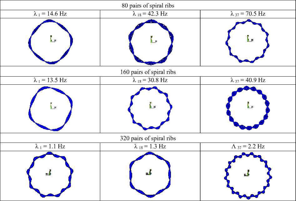
Table 4
Natural waveforms and frequency values when varying the thickness of the ribs
After substituting boundary conditions and some transformations , the expression for finding the natural frequencies of a mesh cylindrical shell has the form
ωmn2 = a · L / (2 · ρ · h · b · L7 · R2), where ω mn is the value of natural frequencies; m and n are integers that determine the number of half– waves in the longitudinal and transverse directions; h is the height of the edges; b is the thickness of the edges.
The analytically and numerically calculated values of the first natural frequencies of the structures are shown in Fig. 9.
а) λ
Hz
б) λ , Hz
16 т
* ρ*
N
Рис. 9. График зависимости значений собственных частот от: а – плотности реберной структуры ρ* ; б – числа пар спиральных ребер N ;
1 –численный расчет; 2 – аналитический расчет
Fig. 9. Graph of the dependence of the values of natural frequencies on: а – densities of the rib structure ρ* ; b – the number of pairs of spiral edges N ;
1 – numerical calculation; 2 – analytical calculation
Analyzing Fig. 9, we note that the values of the first natural frequencies, calculated numerically and analytically, are close and their relative error does not exceed 2%.
Conclusion
The developed and implemented algorithm for calculating the values of geometric and structural parameters of a mesh cylindrical shell without covering with a constant mass allows the formation of rib structures by varying the heights or thicknesses of the ribs with a fixed mass of the structure.
The calculation of the stress-strain state of shells with different rib densities under axial compression showed that the following is true for all structures: annular ribs stretch, and spiral ribs contract.
When choosing approaches to modeling mesh structures, the following should be taken into account:
In the mesh structures formed by varying the thicknesses of the ribs b , the values of the natural frequencies are several times greater than the values of the corresponding frequencies in the structures formed by varying the heights of the ribs h .
– the values of critical loads F kp are higher in mesh structures formed by changing the height of the ribs h than in rib structures formed by varying the thickness of the ribs b .
The formed and given dependences of the maximum longitudinal stresses of the spiral and annular ribs of the shell on the density of the rib structure p* and the height of the ribs h allow us to correctly select the parameters of the mesh structure taking into account its deformation.
References Investigation of the stress state and assessment of the stability of an anisogrid cylindrical shell when changing the parameters of the rib structure under static loading
- Barynin V. A., Bunakov V. A., Vasiliev V. V., Mayorov B. G. [Composite mesh structures (re-view)]. Voprosy oboronnoy tekhniki. Ser. 15. 2001, Iss. 1(123)–2(124), P. 9–16 (In Russ.).
- Azarov A. V. [To the theory of mesh composite shells]. Izv. RAS. MTT. 2013, No. 1, P. 71–83 (In Russ.).
- Vasiliev V. V., Razin A. F. [Composite mesh beam elements for aircraft structures]. Voprosy oboronnoy tekhniki. Ser. 15. Kompozitsionnye nemetallicheskie materialy v mashinostroenii. 2006.
- Burnysheva T. V., Steinbrecher O. A., Ulyanov A. D. [Features of setting boundary conditions in modeling mesh anisogrid structures]. Vestnik Yuzhno-Ural’skogo gos. un-ta. Seriya: Matematich-eskoe modelirovanie i programmirovanie. 2018, Vol. 11, No. 1, P. 137–144 (In Russ.).
- Lopatin A. V., Barylnikova E. A. [Finite element modeling of mesh cylindrical shells]. Resh-etnevskie chteniya: materialy Mezhdunar. nauch.-prakt. konf. [Reshetnev readings: materials of the International Scientific and Practical Conference]. Sib. gos. aerospace. un-t. Krasnoyarsk, 2010, P. 22 (In Russ.).
- Shklovets A. O., Melentyev V. S. Melent’ev. Rabota v CAE-pakete ANSYS MECHANICAL: konstruktsionnyy analiz metodom konechnykh elementov [Work in the ANSYS MECHANICAL CAE package: structural analysis by the finite element method]. Samara, Samara University Publ., 2018, 76 p.
- Kaledin V. O., Razin A. F., Burnysheva T. V., Steinbrecher O. A. [Interpretation of the data of field tests of a shell composite structure under static axial compression]. Zavodskaya laboratoriya. Diagnostika materialov. 2015,Vol. 81, No. 3, P. 53–58 (In Russ.).
- Skvortsov Yu. V., Glushkov S. V. [Using the ANSYS FEM package for solving problems of de-formable solid mechanics [Electronic resource]: interactive. multimed. Manual]. Ministry of Educa-tion and Science of Russia, Samara. state. aerospace. Un-t named after S. P. Korolev (National Re-search un-t). Samara, 2011.
- Ogorodnikova O. M. Konstruktsionnyy analiz v srede ANSYS [Structural analysis in the ANSYS environment]. Yekaterinburg, UGTU-UPI Publ., 2004, 68 c.
- Burnysheva T. V., Kravtsova Yu. A. [Solving the problem of stability of mesh shells made of composite materials under static loading]. Nauch.-tekhnich. vestnik Povolzh'ya. 2012, No. 1, P. 101–105 (In Russ.).
- Zhidkov A. V. Primenenie sistemy ANSYS k resheniyu zadach geometricheskogo i konechno-elementnogo modelirovaniya. Uchebno-metodicheskiy material po programme povysheniya kvalif-ikatsii “Informatsionnye sistemy v matematike i mekhanike” [Application of the ANSYS system to solving problems of geometric and finite element modeling. Educational and methodological material for the advanced training program “Information systems in mathematics and mechanics”]. Nizhny Novgorod, 2006, 115 p.
- Denisov M. A. DZZ komp”yuternoe proektirovanie. ANSYS [Remote sensing computer design. ANSYS]. Yekaterinburg, Izd-vo Ural. un-ta Publ., 2014, 77 p.
- Sachenkov O. A., Sachenkov A. A., Bolshakov P. V., Gerasimov O. V. Avtomatizirovannoe modelirovanie i raschet konstruktsiy v ANSYS: odnomernye modeli [Automated modeling and calcula-tion of structures in ANSYS: one-dimensional models]. Kazan, Kazan. un-t Publ., 2019, 140 p.
- Nasedkin A. V. Praktikum po kursu “Konechno-elementnoe modelirovanie s ispol’zovaniem raspredelennykh vychisleniy”. [Workshop on the course “Finite element modeling using distributed computing”]. Rostov-on-Don, 2011, 46 p.
- ANSYS. Commands Reference. Rel. 11. ANSYS Inc. Houston, 2007. 16. Nemerebaev M. N., Bekmuratov M. M., Orynbayev S. A., Aktaev E. K. Dinamicheskoe povedenie obolochki iz kompozitsionnykh materialov tetrogonal’noy struktury [Dynamic behavior of a shell made of composite materials of tetrogonal structure]. Moscow, Izdat. dom Akad. Estestvoznaniya Publ., 2018, 134 p.
