JPEG Image Steganography based on Coefficients Selection and Partition

Author: Arshiya Sajid Ansari, Mohammad Sajid Mohammadi, Mohammad Tanvir Parvez
Journal: International Journal of Image, Graphics and Signal Processing(IJIGSP) @ijigsp
Article in issue: 6 vol.9, 2017.
Free access
In this paper, we propose a novel JPEG image Steganography algorithm based on partition schemes on image coefficient values. Our method selects the AC and DC coefficients of a JPEG image according to a channel selection method and then identifies appropriate coefficients to store the secret data-bits. As opposed to other reported works, in our algorithm each selected coefficient can store a variable number of data-bits that are decided using the concept called ‘Partition Scheme’. Experimental results indicate the suitability of the proposed algorithm as compared to other existing methods.
JPEG Image Steganography, Partition Scheme, Indicator Sequence, Encoded Shared Key
Short address: https://sciup.org/15014193
IDR: 15014193
Text of the scientific article JPEG Image Steganography based on Coefficients Selection and Partition
Published Online June 2017 in MECS DOI: 10.5815/ijigsp.2017.06.02
Securing the communication tasks has become a prime concern in a world with almost 40% of its population using the Internet [15]. For secure transmissions and communications over Internet, many protocols and algorithms are designed. Steganography is one of these techniques where data or information is hiding in some cover media before transmission. Thus, Steganography can mean camouflage message; the intended secret message must not attract attention to itself. As an object of security, it should be transmitted in such a way that nobody can even suspect it. The information to hide can be text, image, audio or video data. In Image Steganography, secret information or data to be transmitted is called Payload Data / Secret Data / Data Object / Hidden Data Image. The image that is used to hide the secret message is called Cover Object or Cover Image. The cover image encoded with hidden data is called Stego image or Stego Object. Fig.1 shows the basic steps of an Image Steganography method.
Some of the important factors considered in Steganography are confidentiality, integrity and robustness. Confidentiality in Steganography is the ability of Steganographic transmission such that only authorized persons will be able to read the hidden message. Integrity means only authorized persons would be able to modify or change the secret message [3]. Robustness is the ability of the Stego image to withstand under any manipulations such as filtering, compression, etc.
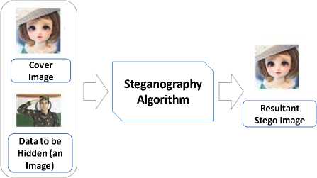
Fig.1. Illustration of the basic steps in Image Steganography.
A qualitative comparison of the proposed method with other related works is given in the next section. Here, the main contributions of this paper are summarized briefly as follows:
-
• Adaptive selection of the fixed number of data bits to be stored in the JPEG image coefficients.
-
• Non-sequential hiding of data bits in DCT block of coefficients, resulting in high security, improved capacity and better PSNR compared to other works.
-
• Ability to work directly on the color JPEG images as cover media.
The rest of the paper is organized as follows. Section II focuses on related works. Section III explains the proposed multiple partition scheme based JPEG image Steganography algorithm. Section IV describes experimental results and analysis. Finally, we conclude the work in Section V.
-
II. Related Work
In this section, we first briefly discuss the file structure of a JPEG image for the completeness of discussion. Then some related works on JPEG image Steganography are discussed. We also briefly compare our method with other reported methods in terms of novelties. A detailed comparative analysis of the proposed method will be given later.
A JPEG image consists of some coefficient matrices along with header information. A typical example of a JPEG image file structure is shown in Table 1 [16]. In the JPEG file structure, we have some metadata about the image. The ‘coef_arrays’ is one of the components in JPEG image file header which is of our interest. This component is a cell array of size 1 × 3 cell, as shown in Table 1. As shown in Fig.3 later, we can divide each cell array into 8 × 8 blocks for easy and fast mathematical operations (less than 8 × 8 block does not contain enough information and greater than 8 × 8 blocks may not be supported by hardware or may take longer time too). Most of the information about the image lies in the DC coefficient, which is the top left corner coefficient of DCT matrix. Other coefficients are known as AC coefficients.
The JPEG coefficient values range from -1024 to +1023. Most of the AC coefficients have values of zero. JPEG compression has two levels: first DCT quantization, which forms the part of the lossy level and the second one, is the Huffman coding that compresses data lossless. JPEG image embedding stores secret data between these two phases [4]. DCT transformed cosine values cannot be calculated back exactly and repeated calculation using limited precision number produces a rounding error hence, it is called lossy compression.
Many algorithms have been proposed for image based Steganography [5-11, 13, 14, 17], some of them work in the spatial domain while others in the frequency domain. Working in spatial domain allows direct modifications of the cover image pixels and provides more capacity. The value of a pixel can be modified according to the scene, like its edges, colors, brightness etc. Spatial domain Steganography techniques include LSB (least significant bit) substitution methods, pixel indicator technique, partition scheme method [12], optimal pixel adjustment procedure, secure key based image realization Steganography, etc.
On the other hand, frequency domain algorithms are more robust compared to spatial domain methods [1]. Frequency domain algorithms work on the rate at which the pixel values change in the spatial domain. Frequency transformation domain can be further divide into two categories: high-frequency domain (deals with edges) and low-frequency domain (deals with smooth and plane areas). Changes in low frequencies are apparent; both DCT (Discrete Cosine Transform) and DWT (Discrete Wavelet Transform) are the two common frequency domain methods that are used for embedding secret data. Literature review reveals that frequency domain is more immune than spatial domain.
Some JPEG Steganography methods that modify the DCT coefficients to embed the secret data are [5, 7, 13]. Zhang et al. [5] proposed JPEG Steganography method based on ‘STCs’ (Syndrome Trellis Coding) and distortion function is used to calculate distortion of DCT coefficient to reduce noise. Wang et al [7] presented JPEG Steganography based on the block entropy of DCT coefficients and STCs. They used uncompressed grayscale images from Core Draw database for embedding and used ‘cost function’ to determine the block complexity and distortion. STC allow embedding messages to a block of coefficients. The proposed distortion function takes into account both the block entropy cost and the flipping cost, to guide the STCs to modify quantized DCT coefficients with minimal flipping distortion in regions of "hard-to-predict". Thus it leads to less detectability in Steganalysis. The different payload test result showed (0.05 to 0.4 bps) at the typical quality factor QF 75. The work in [17] introduced Steganography technique based on integer wavelet transform. The integer wavelet transform is used to extract the coefficients of cover image to embed the secrete data. The coefficients are selected randomly using key.
We now briefly compare our algorithm with other related works and discuss the novelties in the proposed method. The methods in [5, 7, 13] work on the grayscale image and use AC coefficients for embedding data in a zigzag pattern. In our method, we use variable embedding style where we embed data via our partition scheme. A partition scheme selects the numbers of bits (ranging from 1 bit to 8 bits) to be stored in a coefficient, thus providing more security and capacity. Hence, resultant capacity is more than double as compared to the work of Hiney et al. [14]. The proposed algorithm achieves high embedding capacity by using the concept of partition schemes. Our method selects the three JPEG coefficients in every scan and makes one coefficient as an indicator randomly. Indicator coefficient does not store any data; however, it is used to locate the coefficient that will be used to store data bits. Thus, the proposed algorithm store secret data bits in one of the two remaining coefficients based on the coefficient values (coefficient having a lower value). In this approach, our algorithm skips one of the blocks in iteration and puts secrete data in another block. Then in the next iteration, the algorithm puts secrete data in remaining skipped blocks. This approach allows us to reduce distortion and increase security. Our algorithm uses JPEG AC (Alternating Components) as well as DC (Direct Component) to hide secret data bits.
Table 1. Header fields in JPEG file structure. Some values in ‘size’ column are for illustration purposes.
|
JPEG header fields |
Size |
|
image_width |
512 |
|
image_height |
512 |
|
image_components |
3 |
|
image_color_space |
2 |
|
jpeg_components |
3 |
|
jpeg_color_space |
3 |
|
comments |
{} |
|
coef_arrays |
{1x3 cell} |
|
quant_tables |
{[8x8 double] [8x8 double]} |
|
ac_huff_tables |
[1x2 struct] |
|
dc_huff_tables |
[1x2 struct |
|
optimize_coding |
0 |
|
comp_info |
[1x3 struct] |
|
progressive_mode |
0 |
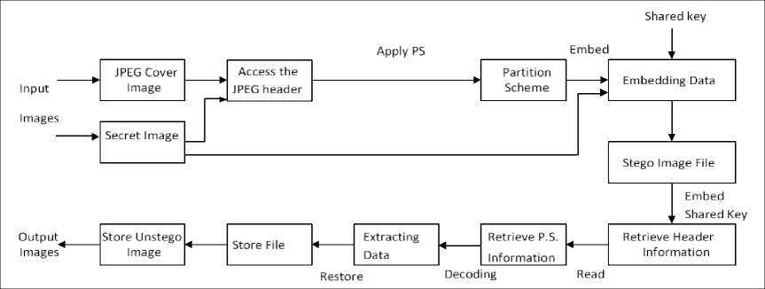
Fig. 2. Block diagram of the proposed method.
-
III. Proposed Method
In this section, we describe our proposed image Steganography algorithm. Fig. 2 shows the functionalities of our method using a block diagram. First, our algorithm reads a cover JPEG image and hidden data (say an image), then it extracts the ‘coef_array’ from the JPEG header from the cover image. It picks up a block of 8 × 8 coefficients non-sequentially. Without any type conversion, like color to grayscale or binary, our algorithm can directly work on AC and DC coefficients to manipulate them. Data is embedding using selected partition scheme and a shared encryption key. It then stores stego file along with this shared key. An exactly reverse process is applied to recover data back at the receiver side. In the following sub-sections, we describe the various steps of the proposed method in more details.
-
A. Coefficient Block and Triodes.
Every JPEG image consists of a coef_array header of size 1 × 3 cells as shown in Table 1. The first cell is of size m × n where m and n are the row and column dimensions of the image under consideration respectively. The second and third cell is of size m /2 × n /2. At a time, the algorithm selects 8 × 8 coefficients from coefficient array as shown in Fig. 3. A triode is a group of three selected coefficients in each 8 × 8 coefficient block. Our algorithm considers four different triodes in each coefficient block named as triode 1, triode 2, triode 3 and triode 4. In each triode, we have three coefficients as shown in Fig.3. The orders of coefficients in a triode are, left to right row wise. The proposed method selects one triode, in turn, its coefficients in every scan and makes one coefficient as indicator randomly. The algorithm then stores secret data bits in one of the two remaining coefficients (whichever is smaller). These processes are explained next.
-
B. Use of a Shared Key.
A shared key is a security mechanism for authentication. It is use to provide security between the sender and valid intended receiver. In this work, we use a shared key (also called Seed key) to generate a matrix of random numbers of the same size as the size of ‘coef_array’ in the cover image. All these random element-values ‘Ev ’ will be in the range 1 > Ev > 0 . Our algorithm uses this ‘ Ev ’ value to make one coefficient as the indicator coefficient in the selected triode, an example is shown in Table 3 later. Our algorithm checks following two cases: Case 1: Ev < 0.33 and Case 2: Ev < 0.66. The algorithm chooses the first coefficient as an indicator if < 0.33 . If Ev > 0.33 but Ev < 0.66 , then our method selects the second coefficient as an indicator. If Ev > 0.66, then the third coefficient is selected as the indicator. For example, consider a matrix element value Ev as 0.5, then our algorithm selects the second coefficient as an indicator. In secret data extraction process at receiver side; the receiver uses the same key value to find the same indicator coefficient. The shared key is common between the sender and receiver to ensure that the stego and unstego processes of the secret data are done correctly.
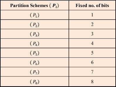
Table 2. Illustration of Multiple Partition Scheme (MPS) as used in this work.
-
C. Multiple Partition Scheme (MPS)
The partition scheme is an arrangement, which decides how many numbers of bits to be stored in a selected coefficient of a selected triode. We have designed a multiple partition scheme (P^), i = 1 to 8, in which a fixed number of bits (either 1-bit or 2-bits….or 8-bits) are chosen to hide in selected coefficient of all triodes of a cover image irrespective of its coefficient values. At a time, only one partition scheme amongst all ( P^) is use as shown in Table 2.
|
Triode 4 |
Triode 3 |
|
0 0 |
0 0 0 0 0 0 |
|
0 0 |
0 0 0 0 0 0 |
|
0 0 |
0 0 0 0 0 0 |
|
0 0 |
0 0 0 0 0 0 |
|
0 0 |
0 0 0 0 0 0 |
|
0 0 |
0 0 0 0 0 0 |
|
0 0 |
0 0 0 0 0 0 |
|
0 0 |
0 0 0 0 0 0 |
|
Triode 2 Triode1 |
Fig.3. Illustration of triodes for embedding data in 8 × 8 JPEG coefficients block.
-
D. Pseudo-Code
The main steps of the proposed MultiplePartitionSchemeStego algorithm are given below. In this proposed MPS algorithm, the cover image is subdivided into nxn blocks of matrices where, n = 8. Here, each block consists of 64 DCT coefficients as shown in Fig.3. The secret data bits are embedded into DCT coefficients to produce stego image. Both the high frequencies as well as the low-frequencies DCT coefficients are used to embed the secret message, an approach which is sometimes called as adaptive method [1]. The proposed algorithm mainly based on the channel selection method introduced in [12] and partition schemes to decide the number of bits to be stored in each selected DCT coefficient. The magnitudes of the coefficients are modifying according to the MPS algorithm.
An example is given in Table 3 for storing data in the DCT coefficients using MPS. Three coefficients of JPEG coefficient matrix get picked up in every scan. Here a , b , and c are the three coefficients with values 50, 30, and 10 respectively in any one of the triodes. Coefficients are sequenced in cyclic order like a -> b -> c -> a.
In Step 1, coefficient ‘c’ is randomly selected as an indicator, which means coefficient ‘c’ will not store any data. In Step 2, since the value of coefficient ‘b’ is lower than coefficient ‘a’, therefore coefficient ‘b’ gets selected to store data. In Step 3, the number of bits gets chosen based on the partition scheme and coefficient value. In addition, coefficient values shown in binary for clarity of presentation. In Step 4, a secret data bit (calculated by partition scheme) is inserted in the lower one bit of coefficient ‘b’, Now the value of ‘b’ changes from 00011110 to 00011111. In Step 5, after changing the bits, the value of coefficients ‘b' changes from decimal 30 to 31. In Step 6, no change in the LSB of coefficient ‘a’ in this case. In case the value of coefficient ‘b’ become greater than ‘a’ after modification, then it will be impossible to retrieve data by the receiver. Therefore, to retrieve the correct data, LSB of coefficient ‘a’ may need to be modified to find the coefficient that stored data at the receiver’s side.
The following rule is use for this purpose. Suppose x and y are the two coefficients other than the indicator. Also, suppose y stores the data. Now, if y comes AFTER x in the cyclic order of coefficients, then LSB of x will be modified so that the LSBs of x and y do not match. Conversely, if y comes BEFORE x in the cyclic order of coefficients, then LSB of x will be modified so that the LSBs of x and y are same (either both are 0 or both 1). Thus, at the receiver, only the LSBs of x and y are checked to decide which coefficient has stored the secret data.
-
IV. Experimental Results
Our proposed algorithm tested on the number of color JPEG images. Some images are resized to 512 × 512 pixel dimensions and some are kept as it is,as shown in Fig 4
-
A. MPS Algorithm Results
For experimentations of this algorithm, we used the multiple partition schemes shown in Table 2. We took secret data image of a soldier as seen in Fig 1. It has 34500 bits of data. We tested our algorithm on different JPEG cover images of different sizes. All cover images along with their sizes are as shown in Fig 4. For simplicity, we took only one image ‘Garden’ as a cover image for illustration purpose. Fig 5 shows output stego images of Garden as a cover image for all partition schemes (P i ) where i = 1 to 8. Their corresponding
PSNR outputs and the percentage coefficient utilizations are shown in Table 4 and Table 5 respectively. The PSNR (Peak Signal to Noise Ratio) is given in formula (1).
PSNR = 10 x log10 C 255^ ’ 5 ) (Decibel). (1)
Where, MSE (Mean Square Error) is given by
П
“^«xs^l^CM-s^ (2)
Here, C ij is cover image and s^ is stego image coordinate’s coefficient values.
If we look at the partition scheme ( P2) in Table 4, we see that for the same size images of Lena, Pepper, and baboon, PSNR are slightly different based on color or other parameters, while the difference in PSNR slightly changes for other arbitrary sized images based on their size, edges and fine details. Up to partition scheme ( P3) or ( P4), PSNR is in the acceptable range but beyond partition scheme ( P4), we can see that value of PSNR starts to decay which is not acceptable.
Algorithm : MultiplePartitionSchemeStego Input : Cover Image, Secrete Image, Shared key
Output : Stego Image
-
1 Begin
-
2 Calculate cover image and data sizes in bits
-
3 Repeat for each 8 × 8 interleaved coefficient block from coef_array header
-
4 Repeat for each triode i where i = 1 to 4
-
5 Assume that a triode has coefficients a , b and c .
-
6 Use the shared key to find indicator coefficient (say a )
-
7 Let, { q, t} ∈ { b , c }, where value ( q ) = min (value ( b) , value(c)) and value (t) = max (value ( b) , value (c)).
-
8 Calculate the number of bits n to be stored in q through partition scheme
-
9 Hide data in q by replacing the lower n bits of q by the n bits from data.
-
10 If value ( q ) > value ( t ), adjust the last bit of t .
-
11 Save new values of a , b , c back into triode i and save 8 x 8 coefficient block to ‘coef_array’ header
-
12 End
Table 3. An example of channel selection method and storing data in the DCT coefficients using multiple partition schemes.
|
Step |
Action |
Coefficient ‘ a ’ |
Coefficient ‘ b ’ |
Coefficient ‘ c ’ |
|
0 |
Pick up the coefficients from selected triple |
50 |
30 |
10 |
|
1 |
Coefficient ‘ c ’ is indicator and is ‘ignored’ |
50 |
30 |
10 |
|
2 |
Smaller coefficient ‘ b ’ is selected |
50 |
30 |
10 |
|
3 |
Select partition scheme and convert Dec-Bin |
00110010 |
00011110 |
10 |
|
4 |
Insert payload data (here 1 bit with value =1) |
00110010 |
00011111 |
10 |
|
5 |
Equivalent decimal |
50 |
31 |
10 |
|
6 |
No change in LSB of ‘ a ’ in this case |
00110010 |
0011111 |
10 |

Fig.4. The list of JPEG cover images used in the experimentations: Lena, Pepper, Baboon, Moon (512 × 512), Doll and Blue Sky (480 × 480), Garden (544 × 544), Cats (456 × 448).
Table 5 shows the percentage of coefficient utilization values for multiple partition schemes. Because of the same image size and same payload data, coefficient utilizations are same for Lena, Pepper and Baboon images and slightly differ for other images. When the partition scheme is changed, percentage coefficient utilization is also changes accordingly. Here percentage (%) coefficient utilization is now decreasing with the increase in partition scheme Pi, which means data hiding is concentric around some part of the image or some area of the image rather than spreading data throughout the image for hiding data. However, concentrated storage of data can give more capacity, thus we can have trade-offs between maximizing capacity and cleanliness or imperceptibility of stego image to better acceptable values.
-
B. Evaluation of Imperceptibility
The imperceptibility evaluation test is based on Embedding Rate & Embedding Capacity utilization of cover image . Let ECCI be the Embedding Capacity of Cover Image under consideration. The ECCI is given by,
ECCI = (^)x ci. (3)
Where, for MPS the constant 'a' has value 16 and it is chosen by experimentations on different JPEG images that keep the stego images undistorted. Variables m and n are the number of rows and columns of the cover image respectively. The value for ECCI is approximately equal to 65536 bits for MPS algorithm for a standard cover image size of 512 x 512 under this value of 'a', while stego image perceptibility is in the acceptable range.
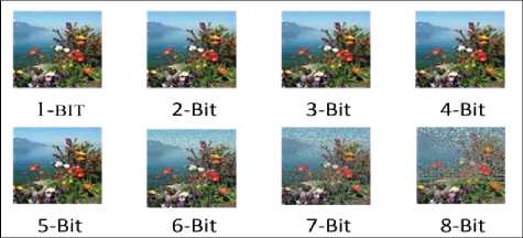
Fig.5. Output results of the proposed algorithm using ‘Garden’ as the cover image with different partition schemes.
Table 4. Multiple partition scheme outputs PSNR comparison for different partition schemes.
PSNR In (dB)
Secrete Data Size (34500 bits)
|
Size / |
Lena |
Pepper |
Baboon |
Moon |
Cake |
Doll |
Garden |
Hoarse |
Cats |
Blue sky |
|
(P i ) |
512 x |
512 × |
512 × |
512 × |
496 × |
480 × |
544 × |
544 × |
456 × |
480 × |
|
512 |
512 |
512 |
512 |
536 |
480 |
544 |
544 |
448 |
480 |
|
|
(P l ) |
66.1163 |
66.1212 |
66.1701 |
66.1256 |
66.0502 |
66.3127 |
65.862 |
65.8669 |
66.5125 |
66.2001 |
|
(P 2 ) |
59.1988 |
58.9499 |
59.2187 |
58.9864 |
59.2153 |
58.266 |
59.4134 |
59.3507 |
58.1284 |
58.0418 |
|
( P s ) |
53.3099 |
53.3099 |
53.3099 |
53.3111 |
53.457 |
52.8503 |
54.2432 |
54.2432 |
52.7578 |
52.7368 |
|
(P 4 ) |
48.5892 |
48.5892 |
48.5892 |
48.5898 |
48.6246 |
48.1741 |
48.8857 |
48.8857 |
47.3327 |
48.1741 |
|
( P s ) |
42.7509 |
42.7509 |
42.7509 |
42.751 |
42.745 |
42.4148 |
43.0369 |
43.0369 |
42.0937 |
42.4148 |
|
(Р б ) |
37.279 |
37.279 |
37.279 |
37.2791 |
37.4374 |
36.7378 |
38.2332 |
38.2332 |
36.4271 |
36.7378 |
|
(P 7 ) |
32.3494 |
32.3494 |
32.3494 |
32.3496 |
32.3944 |
31.4136 |
32.7738 |
32.7738 |
30.7723 |
31.4136 |
|
(P8) |
26.8784 |
26.8784 |
26.8784 |
26.8784 |
26.9106 |
26.431 |
27.2922 |
27.2922 |
25.5382 |
26.431 |
Table 5. Multiple partition scheme outputs comparison for percentage coefficient utilization for different partition schemes.
Percentage (%) Coefficient Utilization
|
Size / |
Lena |
Pepper |
Baboon |
Moon |
Cake |
Doll |
Garden |
Hoarse |
Cats |
Blue sky |
|
(P i ) |
512 × |
512 × |
512 × |
512 × |
496 × |
480 × |
544 × |
544 × |
456 × |
480 × |
|
512 |
512 |
512 |
512 |
536 |
480 |
544 |
544 |
448 |
480 |
|
|
(P 1 ) |
18.75 |
18.75 |
18.75 |
18.75 |
18.889 |
18.75 |
18.75 |
18.75 |
18.859 |
18.75 |
|
(P 2 ) |
13.412 |
13.412 |
13.412 |
13.412 |
13.225 |
15.26 |
11.880 |
11.880 |
17.211 |
15.2604 |
|
( P 3 ) |
8.941 |
8.9417 |
8.9417 |
8.9417 |
8.8168 |
10.173 |
7.9206 |
7.9206 |
11.474 |
10.1736 |
|
(P 4 ) |
6.7062 |
6.7062 |
6.7062 |
6.7062 |
6.6126 |
7.6302 |
5.9405 |
5.9405 |
8.6055 |
7.6302 |
|
(P 5 ) |
5.365 |
5.365 |
5.365 |
5.365 |
5.2901 |
6.1042 |
4.7524 |
4.7524 |
6.8844 |
6.1042 |
|
(P e ) |
4.4708 |
4.4708 |
4.4708 |
4.4708 |
4.4084 |
5.0868 |
3.9603 |
3.9603 |
5.737 |
5.0868 |
|
(P 7 ) |
3.8322 |
3.8322 |
3.8322 |
3.8322 |
3.7787 |
4.3602 |
3.3947 |
3.3947 |
4.9176 |
4.3602 |
|
( P a ) |
3.3531 |
3.3531 |
3.3531 |
3.3531 |
3.3063 |
3.8151 |
2.9702 |
2.9702 |
4.3027 |
3.8151 |
Table 6. PSNR values based on percentage embedding rate and capacity utilization of cover image.
|
Capacity utilized, % RE at (65536 bits) |
100% capacity utilized, % RE = ~ 100% at (65536 bits) |
75% capacity utilized, % RE = ~ 75% at (49152 bits) |
50% capacity utilized, % RE = ~ 50% at (32768 bits) |
25% capacity utilized, % RE = ~ 25% at (16384 bits) |
||||
|
Partition Scheme ( Pt) used |
( P < ) |
( P g ) |
( P2) |
( P 1 ) |
||||
|
Parameter Measure Test Image Size(512 × 512) |
PSNR(dB) |
MSE |
PSNR(dB) |
MSE |
PSNR(dB) |
MSE |
PSNR(dB) |
MSE |
|
Lena |
45.3061 |
1.9314 |
51.9763 |
0.41577 |
59.7488 |
0.069438 |
69.2938 |
0.0077464 |
|
Pepper |
45.0904 |
2.0297 |
51.8515 |
0.4789 |
59.6534 |
0.070981 |
69.2967 |
0.0077057 |
|
Baboon |
45.3547 |
1.9099 |
51.9856 |
0.41488 |
59.7563 |
0.069318 |
69.2974 |
0.0077044 |
Table 7. PSNR comparisons of the proposed algorithm with other JPEG Steganography methods.
|
Cover Image Size (512×512) |
Secret Data Length (bits) used in Proposed Scheme |
Proposed Scheme PSNR ( dB) |
Secret Data Length (bits) used in Other Schemes |
Real-time adoptive RDHS Scheme [6] PSNR (dB) |
Chang et. al Scheme [11] PSNR (dB) |
Transform Domain Scheme [2] PSNR (dB) |
|
Lena |
34500 |
59.19 |
4096 |
47.27 |
40.49 |
44.3 |
|
Peppers |
34500 |
58.95 |
4096 |
44.42 |
41.41 |
44.7 |
|
Baboon |
34500 |
59.21 |
4096 |
31.05 |
35.95 |
44.8 |
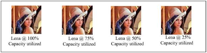
Fig.6. Output stego image results of Lena for different values of ER and ECCI.
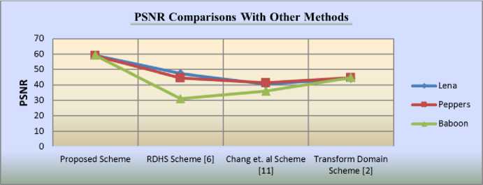
Fig.7. Performance comparisons of the proposed method with three other reported methods.
Let AHD be the actual number of hidden data bits in the cover image and let ER be the Embedding Rate. Then, Percentage Embedding Rate,
(% ER) = ( )x100 Bits. (4)
X cLLl /
Table 6 shows imperceptibility test results based on different embedding rates and different capacity utilized (25%, 50%, 75%, and 100%) of Lena, Pepper, and Baboon cover images. Under ECCI capacity range, the secret bits are embedded in 512 x 512 sized images, using different embedding rates of 100% to 25%. Different secret data approximately equal to 65536, 45000, 32000 and 16000 bits are used to utilize embedding data approximately equal to 65536, 45000, 32000 and 16000 bits are used to utilize embedding capacity as per the need. Measuring parameters MSE and PSNR prove imperceptibility test of the algorithm. Fig.6 shows the stego image outputs for Lena cover image only (for simplicity) at different ER and different ECCI values. Observation shows that at 100% Embedding Rate, partition scheme P4 is used for hiding 65536 bits. Even at 100% capacity utilization PSNR, with a value of 45.30, shows promising output. We can see in table 6 that PSNR is increasing with a decrease in Embedding Rate, Embedding capacity utilization, Number of Secret data bits, and partition scheme Pt. Thus, decreasing MSE and increasing PSNR for all cover images is observed. This observation gives rise to better imperceptibility. The MSE, PSNR readings of Lena, peppers, Baboon cover images are approximately same with little difference, because our algorithm uses the same sized Cover image and fix number of embedding bits in the partition schemes.
-
C. Comparisons with Existing Works
In Table 7 , comparative results for PSNR values of our MPS algorithm with methods in [2, 6, 11] are shown. These results tested on Lena, Paper and Baboon cover images of same dimension 512×512. Methods [2, 6, 11] have used secret data length of 4096 bits only, whereas we have used only near about 55% capacity utilization with data of 34,500 bits as a payload or secret data. The comparison shows that our algorithm’s PSNR on even medium capacity utilization is higher than PSNR of the other three methods [2, 6, 11]. Fig. 7 shows graphically, that the proposed MPS algorithm has high PSNR with almost the same values for all cover images. In contrast, other three methods in [2, 6, 15] have lower and different PSNR values for different cover images, even on low payload data.
-
V. Conclusions and Future Work
In this paper, we have proposed a JPEG image Steganography algorithm to improve the security of data transmission and to provide the finest imperceptibility with negligible distortion. The core of the algorithm is indicator channel selection randomly with a secured key, Multiple Partition Scheme and choosing the interleaved non-sequential 8 × 8 block. High security is achieved with this special arrangement of spreading secret data non-sequentially in every DCT block of the image coefficient. Experimental results revealed better PSNR as compared to other JPEG Steganography methods. In future, we target to design an adaptive partition scheme which will better estimate the capacity of given cover image beforehand and spread the secrete data bits all over the cover image in a better way.
A CKNOWLEDGMENTS
This research is partially supported by Noida International University, India and Qassim University, Saudi Arabia.
References JPEG Image Steganography based on Coefficients Selection and Partition
- Pooja Rai, Sandeep Gurung, M K hose, (March 2015),"Analysis of Image Steganography Techniques", International Journal of Computer Applications, ISSN 0975-8887, Volume 114, Issue 1, pp. 11 – 17.
- Hemalatha, S., U. Dinesh Acharya, A. Renuka, and Priya R. Kamath, (February 2013)."A secure and high Capacity image steganography technique. " Signal & Image Processing An international journal (SIPIJ)), Vol No 4:83.
- Thangadurai, K., & Sudha Devi, G. (January 2014). “An analysis of LSB based image steganography techniques”. In Computer Communication and Informatics (ICCCI), International Conference on (pp. 1-4) IEEE.
- Kaur, Sukhpreet, Sunny Bansal, and Rakesh K. Bansal. (2014) "Steganography and classification of image steganography techniques." In Computing for Sustainable Global Development (INDIACom), International Conference on, pp. 870-875. IEEE.
- Zhang Y, Luo X, Yang C, Ye D, Liu F. (August 2015) “A JPEG-comparison Resistant Adaptive Steganography based on the Relative relationship between DCT coefficients”,10th international conference on Availability and Security on (pp. 461-466). IEEE.
- Guo, L., Ni, J. and Shi, Y.Q., (2014).” Uniform embedding for efficient JPEG steganography”. Information Forensics and Security, IEEE Transactions on, 9(5), pp.814-825.
- Wang, C. and Ni, J, (2012), March. “An efficient JPEG steganographic scheme based on the block entropy of DCT coefficients”. In Acoustics, Speech and Signal Processing (ICASSP), IEEE International Conference (pp. 1785-1788). IEEE.
- Yoon, Sang Moon, and Hae-Yeoun Lee. (2015) "Security Enhancement of JPEG2000 Steganography with Prediction of Code-block Noise Variance Changes". International Information Institute (Tokyo). Information 18.5 (A): 1847.
- Sathisha, N., Babu, K. S., Raja, K. B., & Venugopal, K. R. (March 2015). “Mantissa replacement steganography using LWT”. In Signal Processing, Communication and Networking (ICSCN), 3rd International Conference on (pp. 1-7). IEEE.
- Darvish Morshedi Hosseini, M., & Mahdavi, M. (September 2015). “Modification in spatial, extraction from transform: A new approach for JPEG steganography”. In Information Security and Cryptology (ISCISC), 12th International Iranian Society of Cryptology Conference on (pp. 134-140). IEEE.
- Chang, Chin-Chen, Chia-Chen Lin, Chun-Sen Tseng, and Wei-Liang Tai. (2007),"Reversible hiding in DCT-based compressed images." Information Sciences 177, no. 13- 2768-2786.
- Parvez, Mohammad Tanvir, and Adnan Abdul-Aziz Gutub. (2011) "Vibrant color image steganography using channel differences and secret data distribution." Kuwait J Sci Eng 38, no. 1B: 127-142.
- Luo, W., Heileman, G. L., & Pizano, C. E. (2002). “Fast and robust watermarking of JPEG files. In Image Analysis and Interpretation”. Proceedings. Fifth IEEE Southwest Symposium on (pp. 158-162). IEEE.
- Hiney, Jason, Tejas Dakve, Krzysztof Szczypiorski, and Kris Gaj.(2015) "Using Facebook for Image Steganography". In Availability, Reliability, and Security (ARES), 10th Intl. Conference on, pp. 442-447. IEEE
- Internet users: http://www.internetlivestats.com/internet-users, accessed July 1, 2016.
- JPEG Toolbox: http://www.philsallee.com, accessed Nov 10, 2015.
- Ajeeshvali, N & Rajasekhar, B. (2012). “Steganography based on integer wavelet transform and bicubic interpolation”, International Journal of Image, Graphics and Signal Processing (IJIGSP), 4(12), 26.
