Justification of kinematic, power and design parameters of a roller crusher for disintegration of composite materials waste

Author: Gordeev Y.I., Bukin A.A., Timoshev P.V., Binchurov A.S., Krivov D.A.
Journal: Siberian Aerospace Journal @vestnik-sibsau-en
Section: Technological processes and material science
Article in issue: 3 vol.26, 2025.
Free access
The relevance of the work is explained by the significant problems of the modern aerospace industry, mechanical engineering, energy, mining, processing and other industries in the disposal of waste products made of composite materials and products based on composites of various functional purposes (carbon fiber, fiberglass, metalceramic and cast glass reinforced). The aim of the work is to increase the efficiency of processes for obtaining micron fractions of composite materials waste through the use of an upgraded roller crushershredder design. Computational and experimental studies have substantiated the possibility of increasing the efficiency of waste recycling of composite materials due to their gradual (step-by-step) disintegration. Based on analytical calculations and finite element analysis methods, a kinematic scheme, layout and design of an up-graded prefabricated roller crusher-shredder with working bodies (discs) in the form of an equiaxed contour – a Relo triangle – have been developed. The new design implements a more complex system of forces (compression, friction, alternating cyclic loads) compared to analogues, which makes it possible to increase the speed and productivity of the crushing process. The process of cutting the material using the “rotating scissors” mechanism is implemented between adjacent counter knives of the PK profile, which also contributes to more intensive grinding of the material (especially when processing lamellar or long fragments of waste). The original location and inconsistency of the contact points of the oncoming profiles, the gap between the discs during their rotation creates a rolling effect due to the reciprocating movement of the crushed material, which reduces the risk of jamming and increases the throughput of the grinding rolls and the intensity of the disintegration processes. In order to determine the best performance in terms of the size of the working bodies of the crusher, the gap between them when grinding materials with different sizes and properties, kinematic models were created to simulate the grinding processes and conduct a numerical experiment using finite element analysis methods. It is shown that due to the effective combina-tion of various fracture mechanisms (abrasion, crushing, cutting, alternating loads), the intensity of deformation processes and specific loads on the material increases, but the stresses on the working surfaces of the crusher vary in the range of 430–580 MPa, the safety margin of the working bodies increases to 0.43–0.65, which is a prerequisite for increasing the service life of the workers. grinding elements. The results of calculations using new methods and kinematic schemes show that the design of the upgraded prefabricated roller crusher with working bodies in the form of a Relo triangle has an increased resultant speed (by 30 %) and productivity is almost 2 times higher than the prototype with cylindrical rolls (with the same or comparable sizes of working bodies, kinematic parameters in terms of rotation speed and drive power). Design and technological preparation were carried out and a prototype of the installation for experimental studies was made, which confirmed a good agreement between the calculated and experimental data on the size of the gap, the speed and productivity of the crushing and crushing process.
Composites, roller crusher, Relo triangle, disintegration, utilization of composites
Short address: https://sciup.org/148332093
IDR: 148332093 | UDC: 67.08 | DOI: 10.31772/2712-8970-2025-26-3-432-447
Text of the scientific article Justification of kinematic, power and design parameters of a roller crusher for disintegration of composite materials waste
One of the pressing issues facing the modern aerospace, mechanical engineering, energy, mining, processing, and other industries is the improvement of equipment and technological schemes for products made of composite materials for various functional purposes. Moreover, these problems concern not only the technology of manufacturing products based on composites (carbon plastics, glass plastics, metal-ceramic and cast dispersion-strengthened materials), but also all other stages of the life cycle (CAD/CAM/CAE) – from design, calculation, and prediction of properties to waste disposal. The last stage presents particular difficulties, which are largely due to the structural heterogeneity of composites, significant differences in the properties of the matrix and filler (especially in the form of high-modulus fibers), as well as the high chemical resistance of the phase components. For these reasons, mechanical processing of composites and their waste by cutting and crushing is difficult, as it is accompanied by fiber elongation and destruction of the matrix material under the influence of temperature [1–5]. Therefore, carbon fiber and glass fiber waste are often simply buried or subjected to heat treatment of the matrix to obtain carbon fiber, followed by their reuse, for example, as fillers or reinforcing additives [6–10].
The use of existing crusher designs is limited by insufficient efficiency, since in roller crushers, only compression and crushing forces act on the material, in hammer crushers – impact and abrasion, and in jaw crushers – compression [11–14]. Such crushers are designed to crush a single material or a group of materials with similar properties and sizes. Widely used methods and devices for mechanical crushing also cause difficulties associated with the grinding of plastic materials, therefore, it is necessary to use alternative designs that implement more complex grinding schemes, combining not only the effects of compression, abrasion, and impact forces on the material under alternating loads, but also including cutting processes. The development of such designs naturally requires the creation of new methods for designing and calculating the kinematic, power, and operational characteristics of the equipment.
The aim of the work is to increase the efficiency of processes for obtaining micron fractions of composite material waste by using a modernized design of a roller crusher-shredder.
Numerical and experimental studies of the possibilities for increasing the intensity of grinding by using new designs and kinematics of roller crushers were carried out using the method presented in the block diagram in Fig. 1.
Based on the proposed research methodology, tasks were solved sequentially and in a feedback mode to improve the design and technologies for cutting processing of products made of fibrous composite materials, which ensure the formation of micron-sized fine chips during processing, obtained in the process of high-speed milling. As previously shown by the authors [15–17], this can be achieved by using multi-blade high-speed milling cutters. The tool design and processing modes were optimized using computational and experimental methods to ensure the production of micron-sized chips during mechanical cutting. Fig. 2 shows a 3D model and design of the milling cutters, as well as an image of typical chip fragments obtained during the processing of composites.
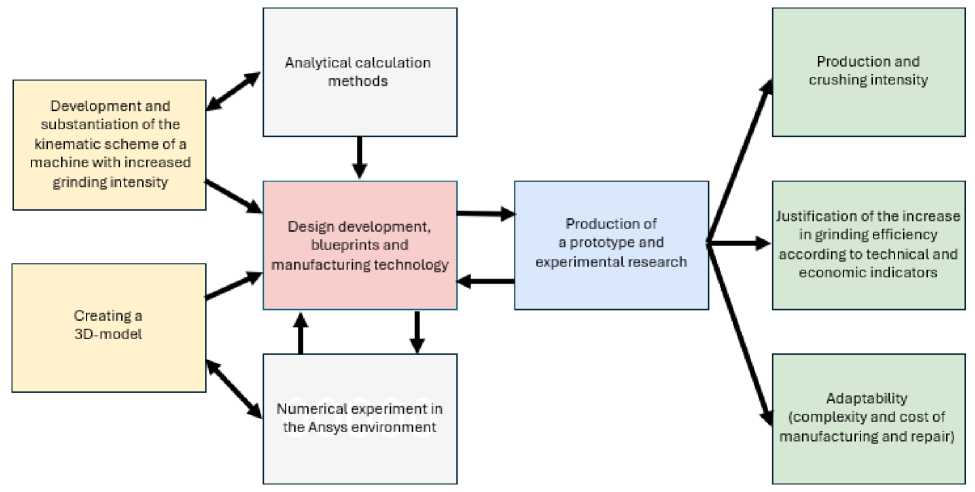
Рис. 1. Структура и методика решения задач исследований
Fig. 1. Structure and methodology for solving research problems
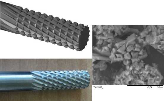
Рис. 2. 3D-модель, конструкция инструмента и морфология стружки после обработки углепластиков
-
Fig. 2. 3D model, tool design and chip morphology after machining carbon fiber reinforced plastics
Chips of this size and morphology, in turn, can be used as “raw material” for further grinding of the material to the size of fibers (whiskers) in new designs of crushers-grinders with working elements in the form of PK profile discs (Relo triangle), shown in Fig. 3. The use of finely crushed chips in such disintegrators is a promising, but not the only, area of research. The main and most relevant area of their practical application is the processing (crushing, grinding) of larger, lumpy or plate-like waste from composite products obtained during the manufacturing process or after preliminary processing of parts that have exhausted their service life (out of service).
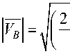
Design of the roller crusher-shredder
The proposed roller crusher-shredder (Fig. 3) consists of two parallel shafts 1 made of hexagonal steel, which are mounted in special bearing supports 2. The supports are designed so that the gap be- tween the discs can be adjusted. Screens 3 with holes corresponding to the required size of the output fraction are attached to the body with screws. PK profile discs 4 are installed on the hexagonal surface of the shafts, in the plane of the sieve, alternating with a maximum angular gap; in this case, the installation option with an angle of 60º is shown. A total of 28 discs are used, 14 on each shaft. The disc package is pressed down with nuts and washers 5 to prevent longitudinal displacement of the assembly. Pulleys are installed on the ends of the shafts, which are driven by a belt from the engine located below, on the foundation of the body part of the structure. The rotation speed of both assembled rolls must be the same to prevent the mechanism from jamming. The base of the РК-profile disc knives on the surface of the hexagon ensures reliable torque transmission and simplifies the assembly, repair, and construction procedures. This reduces the labor intensity and cost of manufacturing and restoring the product.
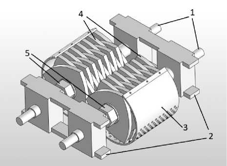
Рис. 3. Конструкции валковой дробилки-измельчителя
-
Fig. 3. Designs of a roller crusher
When using the new design of working parts, the material is subjected to compressive and shear forces, as well as friction forces. Under the action of this system of forces, the material is crushed by compression and crushing, reinforced by shear loads due to the ‘non-cylindrical’ shape of the discs. Between adjacent PK profile knives, the material is cut using a ‘rotating scissors’ mechanism, which also contributes to more intensive grinding of the material (especially when processing plate-like or long fragments).
In addition, the asymmetrical arrangement of the discs (rollers) and the variability of the contact points of the opposing profiles, i.e. the gap between them, provides a rolling effect during their rotation, a reciprocating movement of the crushed material, which helps to prevent rock jamming and increases the intensity of crushing. Fig. 4 shows a conceptual model of the process of changing the gap between the rolls.
A distinctive feature and advantage of the proposed design is the ability to change the size of the resulting fraction of crushed products by adjusting the gap between the working parts.
To visually confirm the nature of the gap change and the dynamics of the pair of rolls, an animated model was created. Screenshots of the animation at different stages of roll rotation are shown in Fig. 5. The model was generated for a set of discs with a diameter of 100 mm.
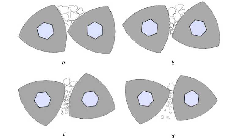
Рис. 4. Изменение щелевого зазора в радиальном направлении при вращении РК-профильных валков на разных этапах взаимного перемещения
Fig. 4. Change in the slot gap in the radial direction during rotation of PK profile rolls at different stages of mutual movement
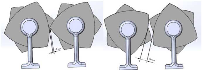
Рис. 5. Изменение щелевого зазора на анимационной модели
Fig. 5. Changing the slot gap on the animation model
Individual animation frames illustrate not only the change in the gap size from the minimum value amin to the maximum value amax at different roll positions, but also the change in the vector of mutual position of the tangents to the roll surface. According to the animation model, the gap varies in the range of 3.4–12.9 mm.
Accordingly, the minimum size of micron powder fractions is about 0.34 mm or 340 μm. However, the design of the tool body provides for the placement of a screen 3 with holes along the contour of the crusher body, which have a size corresponding to the required size of the final fraction (Fig. 3). It is assumed that holes with a diameter of 1 mm will ensure the production of micron powders after additional multiple grinding between the surfaces of the rolls and the surface of the screen.
Diagrams of force and speed, and calculation of operating parameters
The force system implemented in the grinding zone between the composite rolls with typesetting discs in the form of PK profiles, offset relative to each other by 60ᵒ, is alternating and cyclical, in contrast to the constant loading diagram between two solid cylindrical rolls. The diagrams in Fig. 6 illustrate the action of the complex system of multidirectional forces and the kinematics of the grinding process in the new design, which allows to increase the grinding intensity due to the combined action of various mechanisms of material destruction: compression, tension, abrasion, impact, cuttingchipping, and constant change in the direction of the vectors of these forces and their results. The results of a series of experimental design studies conducted by the authors earlier and described in detail in works [18–20] were taken as the basis (prototype) for improving and modernizing the design.
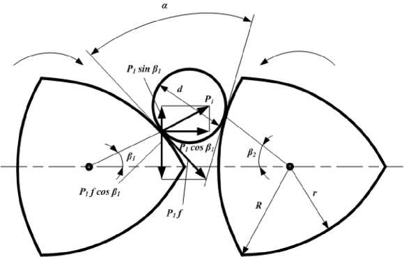
Рис. 6. Кинематика процесса измельчения материала валками РК-профиля
Fig. 6. Kinematics of the process of grinding material using PK profile rolls
The main parameters characterizing the operation of new modernized roller crushers are the angle of attack α, the rotation speed of the rollers, their productivity, and their power consumption. At the moment of gripping pieces of material with a diameter d at the points of contact with the rolls, normal pressure forces P acting on the material at angles β 1 and β 2 arise. The forces P 1 and P 2 are decomposed into the components P 1 f cosβ 1 , P 2 f cosβ 2 , and the repulsive forces P 1 f sinβ 1 , P 2 f sinβ 2 . On the other hand, at right angles to the forces P 1 and P 2, there are friction forces F 1 = P 1 f and F 2 = Р 2 f , which are decomposed into forces Р 1 f sinβ1, Р 2 f sinβ2 and pulling forces Р 1 f cosβ1, Р 2 f cosβ2. Obviously, for the normal operation of a roller crusher, the following condition must be met:
P 1 ⋅ sin( β 1 ) ⋅ P 2 ⋅ sin( β 2 ) ≤ P 1 ⋅ f ⋅ sin( β 1 ) ⋅ P 2 ⋅ f ⋅ sin( β 2 ). (1)
The forces arising in the crushing zone between the working parts of the roller crusher-grinder are limited by the load created by the springs of the safety device. This load depends on many factors and is calculated using known methods for calculating machine parts, depending on the strength of the rock materials and the corresponding crushing forces that must be provided by the crusher mechanisms. The design allows for adjustment of the force by compressing the spring to the required size.
The area over which the average total force between the rolls acts is determined by the formula
F = l ⋅ l1 ,(2)
where l is the length of the rolls, mm; l 1 is the length of the arc, mm.
The length of the arc in the material grinding section is calculated using the formula l1 =0,145⋅D.(3)
Formula for finding the average total crushing force:
P =σ ⋅F⋅µ,(4)
сж сж where µ is the material's looseness coefficient; σсж is the material's compressive strength limit, MPa.
A circle and a PK profile of equal width have an average radius R ср . Moreover, when the radius changes from r to R , the average radius remains constant.
For a PK profile
Р ср = (R + r) . (5)
Thus, when determining the angle of attack α for a PK profile, it is necessary to replace the radii r and R with R ср , and then the determination of the angle of attack of the PK profile is reduced to calculating the angle of attack between the cylindrical rolls using the formula
2 ■ P ■ sin ^ 2 J< 2 ■ P ■ f ■ cos ^ 2 j . (6)
A comparison of the main geometric parameters of the circle and the РК-profile shows that, with the same values of the angle of attack and the perimeter length of the profile sections, the crosssectional area of the РК-profile is 10 % smaller. Therefore, the required torque of the crusher drive is reduced, but at the same time, an increase in the specific load is ensured.
In different positions of the rotating rolls of the РК-profile, the angle of engagement changes, horizontal crushing movements are performed, as well as reciprocating vertical movement of the material being crushed. In this case, the calculation of the angle of engagement is reduced to determining the slot gap at different values of radii and normals to them at the points of contact of the discs in the form of a РК-profile. The material being crushed is exposed to several stress fields at once in at least two planes, and the effect of rolling the material between the surfaces of the discs is also provided, which increases the efficiency of crushing and significantly reduces the likelihood of jamming of the material being crushed due to the non-stationarity of stress fields arising from a system of multidirectional forces (Fig. 7). When the position of the rolls changes, the angle of engagement changes, and its calculation is based on the determination of the slot gap ( a ) and eccentricity ( h ) at known values of the radii and normals to them at the points of contact. The displacement of the crushed material relative to the normal by a distance ( R–r )/2 due to the change in radii from r to R . The maximum possible displacement of the material from the extreme points is equal to ( R–r ).
In addition, the probability of large pieces of material jamming in the gap is significantly reduced due to their ejection from the contact area by multidirectional forces. If the angle of engagement is small enough, the crushed material is captured and crushed; if not, it is ejected from the contact zone.
The productivity of a roller crusher is determined by the following formula:
Q = 1,25 ■п D ■ l ■ a ■ n -ц- p , (7)
where D is the diameter of the rolls, mm; l is the length of the rolls, mm; а is the reduced value of the gap between the rolls, mm; n is the maximum rotational speed of the rolls, rps; ц is the coefficient that takes into account the unevenness of the roll feed; p is the specific density of the material being crushed, g/cm3.
Power N (in kW) consumed by a roller crusher
N = 1400 ■ст- n ■ l ■ R 2, (8)
сж where σсж is the compressive strength of the material, MPa.
To determine the optimal dimensions of the crusher's working parts in terms of productivity, additional calculations were performed for the gap between them when crushing rock materials of different sizes and properties. The results of the calculations are presented in graphical form in Fig. 8. The nonmonotonic nature of the Q (n, D) curve family is similar and allows us to draw one important conclusion: increasing the roll diameter beyond 200 mm is impractical, since all curves practically reach a “plateau.” The data obtained also allows determining the required rotation speed depending on the properties and size of the pieces of material being crushed. The size of the pieces varies from 2 to 10 mm.
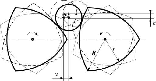
Рис. 7. Схема перемещений материала при дроблении
Fig. 7. Scheme of material movements during crushing
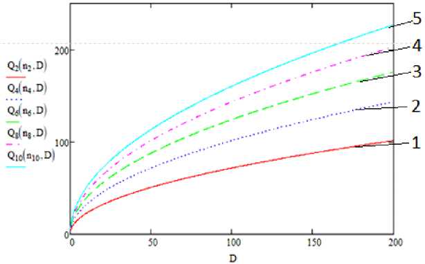
Рис. 8. Влияние диаметра D и размера породы d на производительность Q :
1 – кривая при размере зазора 2 мм; 2 – кривая при размере зазора 4 мм; 3 – кривая при размере зазора 6 мм; 4 – кривая при размере зазора 8 мм; 5 – кривая при размере зазора 10 мм
Fig. 8. Effect of diameter D and rock size d on productivity Q :
1 – curve for standard gap of 2 mm; 2 – curve for standard gap of 4 mm; 3 – curve for standard gap of 6 mm; 4 – curve for standard gap of 8 mm; 5 – curve for standard gap of 10 mm
The speed of material grinding by knives with a working part in the form of a PK profile can be determined by the well-known formula (9) with one significant correction – the radius of the roll affects the slot clearance during rotation. Therefore, the speeds were calculated with an adjustment by introducing the concept of the “radius vector” of the PK profile ( ρ ), which allows determining the extreme (maximum and minimum) values of the variable speed (m/min) at different points on the PK profile contour (10), (11).
V = 2 ⋅π⋅ρ⋅ n
= 1000 , where ρ is the radius vector of the cutting edge contour, mm; n is the number of knife revolutions, rpm.
V max
2 ' П ' pmax ' n
V ■ min
2 ' П ' Pmin ' n
where p max is the maximum radius vector of the cutting edge contour, mm; p min is the minimum radius vector of the cutting edge contour, mm; n is the rotational speed of the first and second shafts respectively, rpm.
The complex kinematics of rotational movements necessitates the determination of the resulting cutting speed, which is calculated based on the kinematic diagram of velocity vector addition shown in Fig. 9 and formula (12).
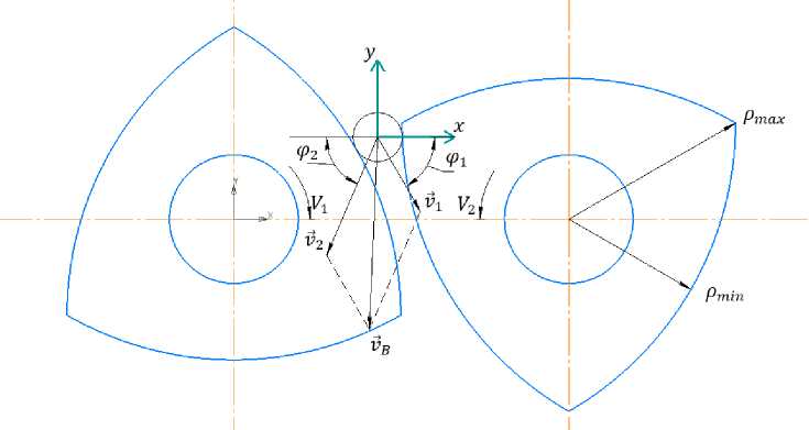
Рис. 9. Схема определения вектора скорости результирующего движения измельчения
Fig. 9. Scheme for determining the speed vector of the resulting movement of crusher
Thus, the speed of the resulting movement of the crusher-shredder with discs in the shape of a PK profile will be finally determined by the formula
' П'Р 1 ' n 1 1000
2' n' p7' n7
' cos m,- 2 2 ' cos
1 1000
+
2 'n'p j ' n 1 1000
. 2' n 'p7' n7 .
• sin m,- 2 2 ' sin
1 1000
, (12)
where m is the angle of inclination between the velocity vector and the coordinate axis x .
As a result of calculations using formula (12), a refined value of the resulting motion velocity Vв was obtained for composite rolls with PK profile discs, which is almost 1.5 times higher than the velocity value determined in accordance with traditional generally accepted analytical calculation formulas for conventional cylindrical rolls [13; 14].
The assumption that changing the shape of the roll profile would increase the intensity of grinding in the working zone was confirmed. As a result of the combined effect on the material being ground, not only the speed but also the productivity of the process increases, which is confirmed by the results of calculations based on the new kinematic diagram. To compare the results obtained, you can use the reduced rotation speed parameter ( n пр) – formula 13. The physical meaning of such a replacement is that at the frequency ( n ) provided by the crusher drive, it is replaced by another frequency that corresponds to the increased resulting cutting speed (formula (12)) for rolls in the form of a PK profile.
This reverse calculation allows us to determine the refined roll rotation frequency and refined performance value via n пр using formula
1000 • v
n пр = Л n • D
Q = Ca • DxD • nxn • K • K2 • к • K, q 12 i where K1, K2, Ki are coefficients depending on the geometry, material dimensions, slot gap, material strength properties, etc.
The results of calculations using new methods and a kinematic diagram show that the design of the modernized prefabricated roller crusher with working parts in the shape of a Relo triangle has an increased resulting speed (by 30%) and a productivity that is almost twice as high as the prototype with cylindrical rolls (with the same, comparable dimensions of the working bodies and kinematic parameters in terms of rotation speed). The comparison results are shown in Table 1.
Table 1
Comparison of calculation results
|
Method of calculation |
V ср , m/min |
Q, g/sec |
|
Analytical calculation methodology [13; 14] |
29.0 |
160 |
|
New calculation method for the РК -profile |
39.6 |
312 |
Finite element analysis
The finite element method and Ansys Workbench software were used to determine the numerical values of contact stresses arising in the grinding zone.
Structural steel, which imitates constructional steel, was selected as the material for the discs. Based on the prototype of the crusher-grinder, 3D models were created with cylindrical bodies imitating the material being crushed in the crushing zone, with diameters of 5, 7, and 10 mm. The use of a mesh consisting of completely identical elements is not advisable, since large elements do not provide sufficient calculation accuracy, and small mesh elements significantly increase the calculation time. Figures 10 and 11 show the diagram and the optimal generated mesh.
Limitations and load types were assigned to the system: Bonded between the roller and the body, and Frictional between the second roller and the body. The left disc is fixed, while the right disc bears the torque. Figure 12 shows the restrictions and loads applied to the system.
The results of the stress-strain state calculations using the finite element analysis method are presented in Table 2.
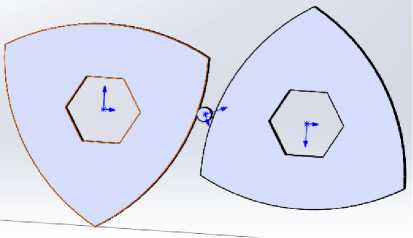
Рис. 10. 3D-модель, имитирующая измельчение материала в виде цилиндра
Рис. 11. Сгенерированная сетка
Fig. 10. 3D model simulating the grinding of material in the form of a cylinder
Fig. 11. Generated mesh
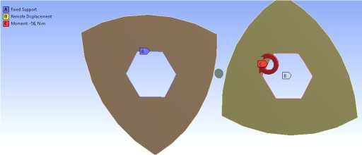
Рис. 12. Задание нагрузок и ограничений системы
Fig. 12. Specifying system loads and limitations
Table 2
Results of numerical analysis in Ansys Workbench
|
Body |
min strain, MPa |
max strain, MPa |
Safety factor |
|
Cylinder D = 5 mm |
0.00032 |
580 |
0.42986 |
|
Cylinder D = 7 mm |
0.00036 |
590 |
0.44342 |
|
Cylinder D = 10 mm |
0.0011 |
430 |
0.6458 |
The effective combination of various crushing mechanisms (abrasion, crushing, cutting, alternating loads) increases the intensity of deformation processes and specific loads on the material, but at the same time, the specific strains on the working surfaces of the crusher are reduced, the margin of safety of the working parts is increased, which ensures an increase in the service life.
Conclusion
Thus, preliminary analytical, kinematic, and force calculations, as well as finite element analysis, have justified the dimensions of the working parts of the modernized crusher-shredder design with rollers in the form of a PK profile with increased productivity. Design and technological preparation were carried out and a prototype of the installation (Fig. 13) was manufactured for experimental studies, which confirmed a good match between the calculated and experimental data on the size of the gap, speed, and productivity of the crushing-grinding process.
Based on the results of the study of the properties of crushed carbon-plastic and glass-plastic waste materials, it can be concluded that the use of a new crusher-shredder allows obtaining micron fractions of powders, which after plasticization and granulation can be reused in various technologies for manufacturing products from composite materials [20].
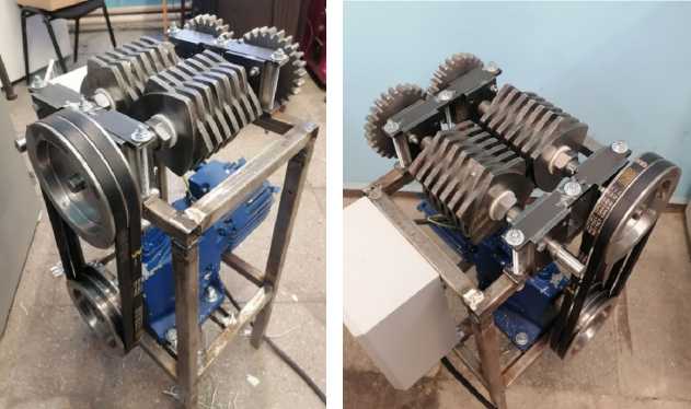
Рис. 13. Конструктивное исполнение варианта измельчителя
Fig. 13. Design of the crusher version
The modernized design of the crusher-shredder implements a complex system of forces (compression, friction, alternating cyclic loads, cutting forces), which increases the intensity, speed, and productivity of the crushing and shredding process. In addition, the use of prefabricated rolls assembled from discs in the shape of a PK profile reduces the costs of manufacturing, repairing, and restoring the structure.
