Knowledge Template Based Multi-perspective Car Recognition Algorithm

Author: Bo Cai, Feng Tan, Yi Lu, Dengyi Zhang
Journal: International Journal of Information Engineering and Electronic Business(IJIEEB) @ijieeb
Article in issue: 2 vol.2, 2010.
Free access
In order to solve the problem due to the vehicle-oriented society such as traffic jam or traffic accident, intelligent transportation system(ITS) is raised and become scientist’s research focus, with the purpose of giving people better and safer driving condition and assistance. The core of intelligent transport system is the vehicle recognition and detection, and it’s the prerequisites for other related problems. Many existing vehicle recognition algorithms are aiming at one specific direction perspective, mostly front/back and side view. To make the algorithm more robust, our paper raised a vehicle recognition algorithm for oblique vehicles while also do research on front/back and side ones. The algorithm is designed based on the common knowledge of the car, such as shape, structure and so on. The experimental results of many car images show that our method has fine accuracy in car recognition.
Template matching, line extraction, vehicle detection, Fourier descriptors, Chain code, Round rate, Circumference ratio
Short address: https://sciup.org/15013055
IDR: 15013055
Text of the scientific article Knowledge Template Based Multi-perspective Car Recognition Algorithm
With the acceleration of the trend of automobile-oriented society, traffic safety problem has already become people’s primary concerns. Although many measures have been adopted to alleviate the traffic pressure such as traffic jam or traffic accident, the actual effect can hardly be impressive. In recent years, in order to decrease the number of accidents, many researches have been made to develop a driver assistant system which will give drivers some advises or necessary warning at on-road situation.
In our paper, we propose different vehicle detection solutions for cars with different direction perspective, respectively front/back, side and oblique.
For the front-view/back-view car, we use the horizontal structures to generate the hypothesis area, and then use the symmetry to verify the area.
For side car, we use foreground/background separation, canny operator and image pyramid to extract the single-edged contour for the ROI, and then extract corresponding features for similarity matching. Those ROI with high similarity with the vehicle class are accepted.
For oblique car, we use template matching to generate the vehicle hypothesis, and then extract the line features from each sub-part of the designed template. The line features are then formed to be a feature vector to do the verification through comparing the Haursdorff distance of the feature vector between the given sample and the vehicle cluster.
We have a review of the related work in Section 2 with the introduction of our proposed algorithm in Section 3, 4, 5. The conclusion and future work are in Section 6.
-
II. Related work
Many related vehicle detection research has been done in recent years. Most of the proposed approach can roughly be divided into three types: motion based, model based and appearance based.
In [1], Z.kim adopts CDT for image segmentation to avoid computational redundancy. Afterwards lines extracted from the CDT result are used to generate the hypothesis with four simple texture features to verify. In [2], they use BMA(Block Matching Algorithm) to detect the vehicle and also estimate the motion. In [3], Sun et al use optimized Gabor filter to extract the features and then use them to train the SVM classifier. In [4], geometric model with its energy function including information of shape, symmetry of the vehicle and the shadows is defined. Then genetic algorithm is adopted to find the global minimum energy value which denotes the possible location of a vehicle. In [5], they improve the symmetrical detection step by analyzing both gray-scale and horizontal/vertical lines.
While many of them have a good performance with real-time application or non-real-time application, they are either only suitable for one perspective of the vehicle or just computational expensive. For [4], their algorithm is computational expensive due to the GA algorithm they use. The same problem goes with BMA algorithm. For [1] [5], their algorithm mostly deals with the front or back side of the vehicle and depends on the horizontal/vertical line feature based hypothesis generation algorithm, which may not be robust with other perspective.
To solve these problem, we propose integrate vehicle detection solutions for cars with different direction perspective, respectively front/back, side and oblique.
Ш. Front/ Back Car Detection
A car comprises a large number of horizontal structures when viewed approximately from the front or back, such as window, bumper, and fascia. Firstly we use canny operator to fetch the edge of the image, afterward four horizontal lines are detected: the top line, the window line, the bumper line and the bottom line, then the hypothesis is generated. At last we use symmetry to verify the hypothesis. The image of the front or rear of a car shows a high degree of symmetry about a vertical axis. If the hypothetical region satisfies the symmetry, then we think the area is a car, otherwise we discard this area.
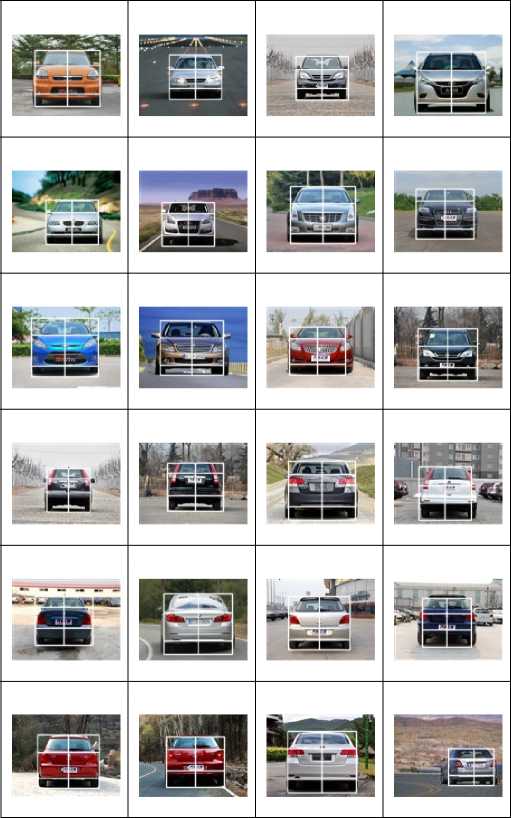
According to the method introduced above, our paper picks 50 images with the size 150*100 as the test samples. Parts of the result are shown in Table I.
TABLE I. the result of the front/back view car
W. Side Car Detection
For side cars, our car detection approach is also divided into two stages in order to be robust and reliable. The first stage generates hypotheses of location and width of potential cars, through the detection of pairs of wheels. The second stage checks the presence of a car behind each hypothesis with template detection.
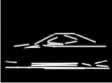
According to statistics by a large number of side cars observed, we find that two wheels and the contour of the cars can always exist in the image. So we use this shape information knowledge to construct the deformable template from a prototype as show in Figure 1.
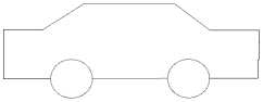
Figure 1. The template of the side car(Red is the main part of the template)
The template is composed by two wheels and the contour of the car. Two wheels are one of the most important parts of the side view car. The contour can be divided into the top line, two oblique lines about windows, and the bottom line between two wheels. Other lines can be gotten by the car's structure. This template fits most cars and its size is determined by the matching results.
Since the template has been constructed, now our approach of the side car detection is described as follows. We detect pairs of wheels and a bottom line between two wheels to generate the hypothesis areas to reduce the computation. Then, in the hypothesis area, we find the top line, and then two slope lines are detected. At last, we construct the car model. When all of these steps are finished, we think a car is detected. The specific process will be introduced in the remainder of this section.
(a)

(b)
(c) (d)
(e)
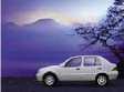
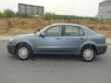
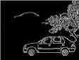
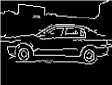
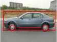
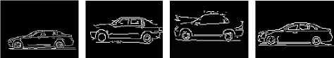
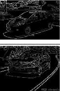
Figure 2. the steps of hypothesis: (a) original image (b) edge image (c) wheel detection (d) wheels and a horizontal line (e) hypothesis generation area
-
A. Hypothesis Generation: detecting two wheels
A car hypothesis is generated from two wheels detection. Every side view car has two wheels in the image and all car wheels are round. Because of a wheel is a circle, we can find wheels by detecting circles. Circles are detected by Hough transform. However, this method would detect all circles some of which may not be the wheels .To address this problem, when finding for circles, some rules are used to filter the circles to extract wheels.
First, a car has two wheels from one side viewing. They have the same size and exist in the same horizontal line in the image. At most of the time they do not appear at the top of the image. Second, between two wheels there exists a horizontal line. If this line can be extracted then we can assure these two circles are the wheels. When the two wheels are extracted, we can estimate the rough width of the car in the image according to the distance between two wheels. The height of a car is about two-thirds and the width is about three-fifths of the distance between two wheels. Then by this knowledge the bounding boxes of the hypotheses can be generated.
All the steps of the algorithm about hypothesis generation are shown in figure 3.
-
B. Line segments extraction Based On Line Fitting
To make a preparation for the following template matching procedure, we should first extract the line segments included in the edge image. The traditional line extraction algorithm such as Hough transform can roughly pick out some relatively long line segments included in the edge image, but the accuracy can hardly satisfy some practical application especially when some short line segments are required. Thus, in order to extract line segments more comprehensive and accurate, our paper raised a line extraction algorithm based on line fitting.
Firstly, we have a brief introduction of the line fitting algorithm based on least squares. Assuming ( xi , yi ) (i=1...N) is a set of data points in two-dimensional space, for any given line in the space y = f ( x ) = ax + b , we record the vertical distance between ( xi , yi ) and the given line as the deviation from the point to the line. The theory of the line fitting algorithm based on Least squares is that a and b correspond to the slope and intercept of that when the sum of squares of the deviation from each point in the data set to the given line reaches its minimal. The details of the steps to find a and b are as follows.
Find the sum of squares of the deviation:
N
E = E ( У. - ax . - b ) 2 (1)
i = 1
Find the partial derivative of the sum of squares of the deviation to the slope a:
d E
— = E 2( y. " ax b )( - x i ) = 2 E ( ax . + b - y . ) (2)
d a ^ t!
Find the partial derivative of the sum of squares of the deviation to the intercept b:
Ц = 2 S ( ax i + b — y^ (3) d b ‘‘ = 1
Let ^ E and ^ E be 0, then we get:
da db b = (Ey.)/N - a (E x)/N (4)
a = [ N E x^^ ( E x E y . )]/[ N E x" - ( E x . )2] (5)
With the basic idea of the line fitting algorithm based on Least squares, our line extraction algorithm is as follows:
-
(1) From the upper left corner of the hypothesis area, with the sequence of left to right and up to bottom, to locate a pixel whose value is non-zero.
-
(2) If a non-zero pixel is located, then check the eight-neighborhood of it. If there exists a non-zero point, we set it to the current point and again check if its eight-neighborhood has a non-zero pixel. We repeat the operation until four non-zero points are visited.
-
(3) Then, we put all the four non-zero points into a empty point array and use line fitting algorithm to calculate the slope of the line fitted by the point array. The last point in the array is set to be the current point.
-
(4) Check the eight-neighborhood of the current point, if a non-zero point is found, add it to the array and recalculate the slope of the line fitted by the changed point array.
-
(5) If the difference between the slope of the new fitted line and that of the previous one is larger than a predefined threshold, we exclude the new added point from the point array; Otherwise, we set the new added point to be the current point and repeat (4) until the eight-neighborhood of the current point does not have any non-zero pixel. Then the final line we extracted is defined by the first and the last point in the array. The experiments on some images are shown in the Figure 4.
C.Ver f cat on:kownledge-based template detect on
With the line extraction algorithm above, we can now verify the car hypothesis by detecting templates among the extracted line segments in the hypothesis area using the shape knowledge. Steps are as follows:
Step 1: For each detected oblique line, if two lines meet the following requirements, we consider them as the window lines and record them as s 1 and s 2 . (1)The endpoints of the two lines are basically at the same level. (2)The length of the two lines is nearly the same. (3)The slope of the oblique lines total about 180 degree.
Step 2: Above s 1 and s 2 , we find a horizontal line recorded as h 1 which meets the requirement that the x coordinate of two endpoints of the line should be in the middle of s 1 and s 2 .
Step 3: If h 1 , s 1 and s 2 are all found, then we construct the contour of the car according to the template. At last, a car is detected.
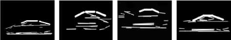
With the above algorithm, we pick some images to show the results of the steps in Figure 3. We can find that the three separate lines can always be detected, thus we can construct the template based on these three separate lines and two wheels. The final results of the experiments will be shown in Figure 4. and analyzed in the next.
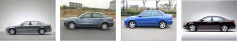
whose roof is oval not horizontal can not be detected by our algorithm. This problem will be solved in the future work. Example results of detected cars are shown in Figure 4. As in Figure 4. The algorithm is able to detect cars in side view from background and the template outlines the contour of the cars very well.
(a)
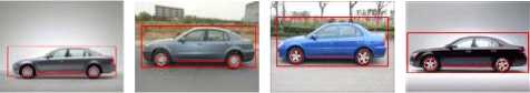
TABLE II. .Detetion results for different test sample sets.
|
sets |
1 |
2 |
3 |
|
Number of observed cars |
50 |
100 |
150 |
|
Hypothesis Generation |
46 |
90 |
144 |
|
Hypothesis verification |
45 |
88 |
141 |
|
Detection rate |
90% |
88% |
94% |
(b)
(c)
(d)
(e)
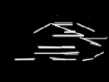
Figure 3. the steps of verification: (a) original image (b) hypothesis (c) edge (d) line detection (e) three lines extraction ( the rough lines )
The whole system has been implemented in Matlab and C++. We have tested our method on static images collected from various sites on the World Wide Web. We
show the results obtained in Table 1 for different test
sample sets.
(1) (2)
(6) (7)
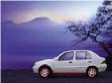
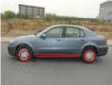
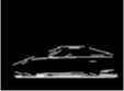
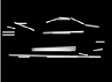
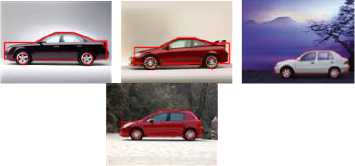
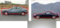
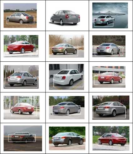
Figure 4. some examples of car detection
In our tests, we found that our method has 90.7% average success rate in detecting cars. There are some instances that we can not detect. Such as some of the cars
-
V. Oblique Car Detection
The existing car recognition algorithm mainly based on the front/back and side vehicles, and most of them can not be applied to detect oblique vehicles which classify as front-oblique and back-oblique ones. In order to enhance the robustness of our car recognition algorithm, our paper proposed an oblique car detection algorithm based on template matching. The algorithm is also composed of HG and HV steps.
-
A. Hypothesis generation
Some existing hypothesis generation method base on template matching mostly take use of the horizontal/vertical lines in the edge image. This strategy may perform well for front/back and side vehicles, but will not be robust for oblique ones. In our paper, we construct two templates for front-oblique and back-oblique ones respectively. The template is formed by both horizontal lines and oblique lines and can be dynamically changed. To make a preparation for the following template matching procedure, we should first extract the line segments included in the edge image. The traditional line extraction algorithm such as Hough transform can roughly pick out some relatively long line segments included in the edge image, but the accuracy can hardly satisfy some practical application especially when some short line segments are required.
Template matching
With the line extraction algorithm above, we can now generate the vehicle hypothesis by matching templates among the extracted line segments.
To design the template that will fit most vehicle, we firstly divide vehicles into several groups considering their perspectives. For different perspectives, we design different templates based on their visual features in the edge image. The template is formed by several line segments and is dynamically changed according to the size of the vehicle in the image. As for the front/back and side ones, there have been various of approaches, so our paper focus on the front-oblique and back-oblique ones which is seldom studied with our knowledge.
Front-oblique Templete Matching
For the edge image of the front-oblique car, we assume that some lines can always be detected: the separate line between the front board and the road, the separate line between the side board and the road, the separate line between the front board and the front window, the separate line between the front window and the roof. The procedures for the template matching are illustrated in Table VIII.
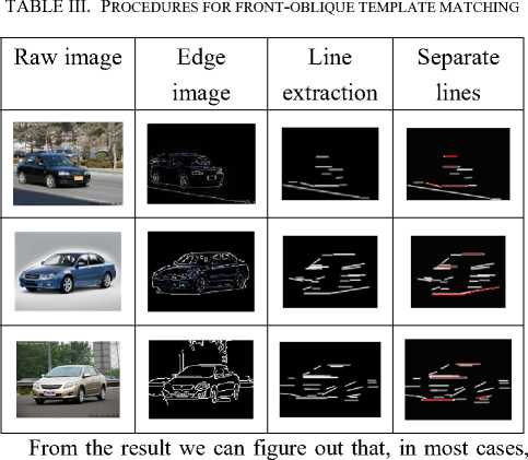
the described four separate lines can be detected. Thus, we can construct the template as Figure 5. :
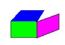
Figure 5. Front-oblique template structure
With the template shown above, now the hypothesis can be generated by the following steps (The test images are all 150*100):
Step 1: From the bottom of the image to the top of it, we check detected horizontal lines in each row for one with 15-30 pixels in length (the range can be changed according to the size of the vehicle in the given image). If a horizontal line that meets this requirement is found, we record it as h 1 and turn to Step 2.
Step 2: For each detected oblique line, if it meet the following requirements, then we consider it as the separate line between the side board and the road and record it as s1 .(1) The y coordinate of the lower vertex of this oblique line should not be bigger than that of h1 .(2) The x coordinate of the lower vertex of this oblique line should not be smaller than that of the right vertex of h1 and the difference should not be bigger than 30 pixels (if the vehicle is toward its left); The x coordinate of the lower vertex of this oblique line should not be bigger than that of the left vertex of h1 and the difference should not be bigger than 30 pixels (if the vehicle is toward its right). (3) The slope of the oblique line should be less than 30 degree.
Step 3: In the region which is 10–40 pixels in the top of the h 1 , find a horizontal line which meet the following requirement and has the lowest y coordinate and record it as h 2 : (1) The length of the horizontal line is bigger than 10. (2) The difference of the x coordinate between the left vertex of h 1 and that of h 2 should be less than 20 (3) The difference of the x coordinate between the right vertex of h 1 and that of h 2 should be less than 20. Then we record the vertical difference between h 1 and h 2 as offset .
Setp 4: In the region which is 10–30 pixels in the top
h of the 2 , find a horizontal line which meet the following requirement and has the lowest y coordinate and record it as h3 : (1)The length of the horizontal line is bigger than 10 and less than 30. (2) The absolute value of the vertical difference between the h2 and h3 should be bigger than 5 and less than the offset /1.5 . (3) For vehicles whose body towards its left, the x coordinate of the left vertex of h3 should be 5-20 pixels bigger than that of h2 , and the x coordinate of the right vertex of h3 should be 5-20 pixels bigger than that of h2 . For vehicles whose body towards its right, the x coordinate of the left vertex of h3 should be 5-20 pixels less than that of h2 , and the x coordinate of the right vertex of h3 should be 5-20 pixels less than that of h2 .
Step 5: Adjust h 1 , h 2 , h 3 and s 1 according to the designed template. For example, extend h 1 and s 1 to make them intersect, adjust the x coordinate of the two vertexes of h 1 and h 2 to make the x coordinate of their corresponding vertex equal and so on.
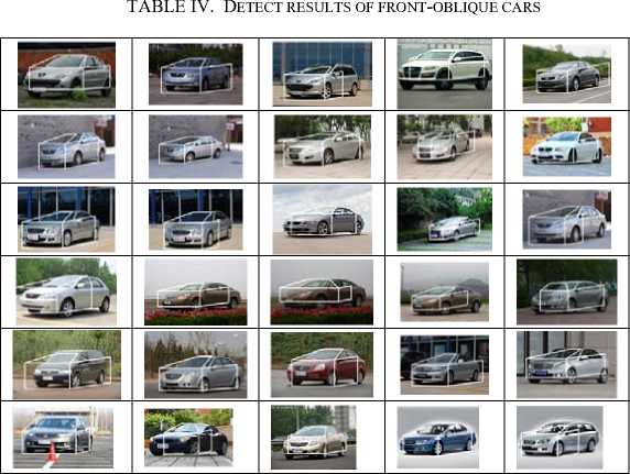
According the algorithm introduced above, our paper pick 100 images with the size 150*100 as the test samples. Parts of the result that a correct vehicle hypothesis is generated are shown in TABLE IV. .
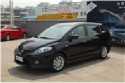
From the test result, we find that in the following two cases, our algorithm doesn’t work well: (1) the color of the car body is black. (2) The vehicle is at certain angle with the camera. The example is shown in TABLE V. .
From the two examples above, we can find out the reason why the mismatch happens under the two conditions. When the color of the car body is black, the separate line between the car body and the shadow is weak and is very difficult to be detected. So the separate line we actually detect is always the separate line between the shadow and the road. This separate line can sometimes be a curve but not a horizontal line. So under this condition, we may not be able to locate vehicle through our proposed method.
separate lines can always be detected, thus we can design the template based on those three separate lines. The template is shown in Figure 6. :
TABLE V. Cannot be detected image
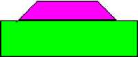
Figure 6. Back-oblique template structure
Raw image
Edge image
The vehicle is at certain angle with the camera
Mismatch reason The color of the car body is black
Since the template has been constructed, now we can introduce our template matching strategy for back-oblique cars. The details are as follows:
Step 1: From all the extracted oblique lines, Find a pair that meet all the following requirements and record them as s 1 , s 2 , here s 1 is in the left side of s 2 : (1) the sum
When the vehicle is at certain angle with the camera, the separate line between the car body and the shadow or the separate line between the shadow and the road is oblique line. So the above algorithm can not locate the vehicle.
Back-oblique template matching
After examine many back-oblique cars, we find out that the template designed for front-oblique may not be suitable. Because the height of the rear of the vehicle may be a little higher than that of the front of the car, the situation will be a little bit difficult. Thus, we design a template that is more general but not as accurate.
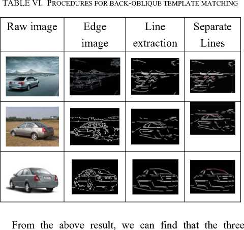
Considering images of back-oblique cars, we can find that three separate lines can always be found: the separate line between the vehicle window and its top and the separate line between two wings of the vehicle window and the car body. To demonstrate our assumption, we test several images to check whether or not the three separate lines can be found. Parts of the results are shown in TABLE VI. :
of the angle between s 1 and horizontal axis and the angle between s 2 and horizontal axis should be bigger than 130 degree but less than 200 degree, while both of the two angles should be bigger than 20 degree but less than 160 degree. (2) The difference between the y coordinate of the upper vertex of s 1 and that of s 2 should be less than 15 pixels, and so does the lower vertex. (3) The difference of x coordinate of the upper vertex of s 1 and that of s 2 should be less than 20 pixels.
Step 3: After locating the oblique line pair corresponding to the separate line between the two wings of the vehicle window and the vehicle body, now we should find the separate line between the vehicle window and the vehicle roof. From all the extracted horizontal lines, if any one of them meets the following requirements, we consider it to be the needed one and record it as h 1 : (1) The difference between the y coordinate of h 1 and that of the upper vertex of s 1 , s 2 should be less than 15 pixels.
-
(2) The x coordinate of the left vertex of h 1 should be bigger than that of the upper vertex of s 1 and the x coordinate of the right vertex of h 1 should be less than that of the upper vertex of s 2 .
Step 4: Extend s 1 , s 2 and h 1 to make them intersect with each other. Make the y coordinate of the lower vertex of s 1 , s 2 equal and connect them with a horizontal line. Generate a rectangle whose height is 1.5 times bigger than the vertical length of s 1 , s 2 with the width slightly larger than the horizontal distance between the lower vertex of s 1 and s 2 .
Results of back-oblique detection
TABLE VII.
meaningless and disorganized. For the side board, considering the appearance of it, there should be several lines parallel to the edge line of the side board. To demonstrate the rationality of the template features, we have several images for test. Parts of the result are shown in TABLE VIII. :
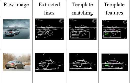
TABLE VIII. Procedures for front-oblique hypothesis
VERIFICATION
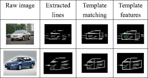
From the result we can figure out that, for front-oblique template, there is certain relationship between the number of meaningful lines in each sub-parts of the template. A vehicle hypothesis can be verified only when the line features for each sub-part satisfy the relationship.
As for back-oblique template, since it is composed of two parts: the pink part and the green part in Figure 6. . For pink part, it corresponds to the back window and the side window; there will be several lines parallel to the two wings (or have a very close slope). For the green part, it corresponds to the side board and the back board; there will be several horizontal lines as the existence of lights, license plate and so on. What’s more, the horizontal lines will be in one side of the green part. Parts of the experimental result are shown in Table XIV.
TABLE IX. Procedures for back-oblique hypothesis
B. Hypothesis verification
The features we used to verify a vehicle hypothesis generated by template are called template features. The template features are composed of the line features extracted from every sub-parts in the template. Here the line features are the number of meaningful lines for each sub-part.
Take the front-oblique car as example, its corresponding template are formed by three sub-parts: the front window(the blue part), the front board(the green part) and the side board(the pink part) respectively.
Now, we can decide the meaningful line features in each sub-parts. For the front board of the vehicle, because of the existence of license plate, lights and grille, there should be a lot of horizontal line segments. For the front window, when there is nobody in the driving room, there are barely any edges in this area; when the driving room is not empty, although some edges are existed, but they are
VERIFICATION
-
C. Vehicle classification
After the template features have been extracted, now we should pick a classifier to train the test set. In our paper, we use fuzzy clustering to find the clustering center, and then adopt Hausdorff distance to find the similarity between the test sample and the cluster. If the distance is less than a predefined threshold, we will consider the test sample as a member of the cluster. We pick 50 hypothesis generated by the above algorithm which include cars for test., the corresponding result is shown in Table X. The recognition result can be divided into four categories: TT, TF, FT and FF. Here, TT means considering a true detection as a true one; TF means considering a true detection as a false one; FT means considering a false detection as a true one; FF means considering a false detection a false one.
TABLE X. detection result
|
numbe r |
T T |
T F |
F T |
F F |
Detectio n rate |
Misse d rate |
|
|
Positiv e test sample s |
50 |
44 |
6 |
/ |
/ |
88% |
12% |
И. Conclusion and future work
In a word, our paper raises a way to detect vehicles at different perspective. For vehicles with different perspective, our paper gives different solution. For front/back vehicle, we take use of the symmetrical feature of the vehicle while for side vehicles, we describe a side-view car detection algorithm based on template detection. The template is constructed according to car shape knowledge. The algorithm can roughly be divided into two stages, hypothesis generation and hypothesis verification. For oblique vehicle, we use template matching method to generate the hypothesis. The template is dynamically changed according to the real size of the potential vehicle in the given image. After the hypothesis is generated, we use line features within each sub-parts of the template to do the verification.
Since the template matching method is based on the line extracting result, our paper addressed a line extraction algorithm that has better result than many existing ones. The algorithm is based on line fitting method. For each step, a point is considered a member of the current line if the slope of the current line generated by line fitting is similar to that of the last one. Here the similarity is decided by a predefined threshold.
For further research, considering the drawback of our algorithm, we will do some improvement at the following aspects: (1) Taking video information into consideration, so that we can estimate the size of the vehicle in the image through camera calibration and therefore decide the template parameters (length of the separate line, the distance between each lines, etc) automatically according to it. (2) Adding some local features and some other template features to enhance the verification, such as wheels, lights, license plate and so on. (3) Make the template more flexible so that it can also work for the cases we described before. For example, let the template can accept an oblique line as the separate line between the car body and the shadow.
References Knowledge Template Based Multi-perspective Car Recognition Algorithm
- Z.Kim. Realtime Obstacle Detection and Tracking Based on Constrained Delaunay Triangulation, IEEE Intelligent Transportation System Conference, pp.548-553,2006
- Zehang Sun, George Bebis and Ronald Miller. On-road Vehicle Detection Using Evolutionary Gabor Filter Optimization. IEEE transactions on ITS. 2005
- Luigi Di Stefano, Enrico Viarani. Vehicle Detection and Tracking Using the Block Matching Algorithm. Proc. of 3rd IMACS/IEEE. 1999
- J.M.Collado, C.Hilario. Model Based Vehicle Detection for Intelligent Vehicles. IEEE Intelligent Vehicles Symposium. 2004
- M.Bertozzi , A.Broggi, A.Fascioli. Stereo Vision-based Vehicle Detection.IEEE INTELLIGENT VEHICLES SYMPOSIUM. 2000
- Yi Lu, Bo Cai, Dengyi Zhang. Contour based car recognition algorithm. CNMT2009
- Zehang Sun, George Bebis and Ronald Miller. On-road vehicle detection: a review. IEEE Trans. Pattern Analysis and Machine Intelligence, vol.28, no.5.2006
- Ronan O’Malley, Martin Glavin. Vehicle Detection at Night Based on Tail-Light Detection. National University of Ireland,Galway.
- Marie-Pierre Dubuisson Jolly. Vehicle Segmentation and Classification Using Deformable Templates. IEEE transactions on pattern analysis and machine intelligence, Vol 18, No.3 1996
- Bo Cai, Dongru Zhou. Content based video classification and retrieval [D].Wuhan University 2003.10(in Chinese)
