Large size metal-clad ingots rolling process analysis using finite elements method

Author: Yashin Vasiliy V., Beglov Erkin D., Aryshensky Evgenii V., Latushkin Ilya A.
Journal: Журнал Сибирского федерального университета. Серия: Техника и технологии @technologies-sfu
Article in issue: 4 т.11, 2018.
Free access
Under real rolling conditions, plastic strain is accompanied by inevitable uneven distribution of the metal movement velocities, strains and stresses both in height and width of the actual deformation zone of the rolled metal. With the simultaneous plastic strain of various metals, there is still a layered inhomogeneous strain, which is caused by the fact that at the same time in a plastic zone there are metals possessing different mechanical properties. The inhomogeneity of layered strain is one of the most important and complex problems of the theory of simultaneous plastic strain. A considerable number of works, has been devoted to the investigation of this problem, but many of the issues that we should deal with when developing the technology for the production of clad products remain unclear. In this article, the authors carried out a study of the process of rolling high cross-section ingots with cladding plates, using finite element modeling in the DEFORM software. Relationships are determined to take into account the strain inhomogeneity and the influence of various parameters on the depth of strain penetration into ingot.
Rolling, strain, aluminum alloys, finite element modeling, ingot cladding
Short address: https://sciup.org/146279370
IDR: 146279370 | UDC: 669.621.62.412 | DOI: 10.17516/1999-494X-0064
Анализ процесса прокатки крупногабаритных слитков с плакирующим материалом при помощи метода конечных элементов
В реальных условиях прокатки пластическое деформирование сопровождается обязательным неравномерным распределением скоростей движения металла, деформаций и напряжений как по высоте, так и по ширине фактического очага деформации прокатываемого металла. При совместном пластическом деформировании различных металлов возникает еще и послойная неравномерность деформации, которая обусловлена тем, что в пластической зоне одновременно находятся металлы, обладающие различными механическими свойствами. Неравномерность послойной деформации является одной из самых важных и сложных задач теории совместного пластического деформирования. Исследованию этой проблемы посвящено значительное количество работ, однако многие вопросы, с которыми приходится сталкиваться при разработке технологии производства плакированных изделий, остаются еще не выясненными. В настоящей статье авторами проведено исследование процесса прокатки слитков высокого сечения с планшетами методом конечно элементного моделирования в программном комплексе DEFORM. Определены зависимости для учета неравномерности деформации и влияние различных параметров на глубину проникновения деформации в слиток.
Text of the scientific article Large size metal-clad ingots rolling process analysis using finite elements method
layer thickness increase, layerwise deformation non-uniformity increases [4]. Construction cladding distribution along the strip surface is less uniform compared to protective and technological cladding. It is especially critical for the ingots with the thickness above 500 mm. cladding thickness will be up to 28 mm in this case. The issues, associated with rolling practice development for this composition (mismatch of nominal and actual cladding thickness values, excessive blistering, non-uniform cladding layer distribution, rolling force increase with process efficiency drop due to pass reduction decrease) make this task up-to-date: large size metal clad ingots rolling practice study.
Process modelling
DEFORM software, enabling metal pressure forming processes modelling using FEM, will be applied for this study. Modelled experiments variables are listed in the Table 1.
The process is symmetrical, therefore for the purposes of the study we’ll consider only top portion of the slab and a single roll. It is known, that insignificant widening (max 50 mm) occurs during 1400 mm – 2000 mm wide ingots rolling [5], therefore we’ll apply 2D mode for modelling, with stressed-strained diagram – plane strain. Grid size both for cladding and ingot is selected based on FEM discretization, corresponding to at least 5 rows in a clad plate (see Fig. 1). Clad plate is fixed to the ingot, i.e. clad plate bottom surface speed is equal to the ingot top surface speed. Roll and metal friction coefficient is selected considering running the initial passes without emulsion, with high friction coefficient μ=0,4 (Coulon law).
Results analysis
During high section strip rolling the neutral line with the metal speed equal to the roll linear speed, has curved shape due to non-uniform deformation (Fig. 2). On the line right-hand side the metal speed is lower, than the roll speed, while on the left-hand side it is higher.
The situation changes dramatically during clad metal rolling.
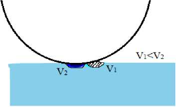
Let’s review two cases, when clad metal is not welded to the ingot yet. This stage is characterized by soft layer deformation, while hard layer is subjected to minor elastic deformation. Due to stretching the clad plate deformed part speed exceeds the roll speed, while non-deformed cladding plate part speed is lower, that the roll speed. Cladding plate portion outside the strain center and attached ingot move like a solid body with the speed exceeding the roll line speed (as stated earlier) (Fig. 3).
Table 1. Experiments plan
|
Cladding thickness, mm |
Ingot thickness, mm |
Roll diameter, mm , |
°// * / ст/ |
Reduction, mm , |
|
0, 5, 13, 15, 17, 22, 25, 28 |
526, 516, 500, 496, 492, 482, 476, 470 |
900 |
0,4 |
10 |
|
— 28 |
470 |
900 |
0,4 |
20, 25, 30, 40 |
|
28 |
470 |
900, 1000, 1200, 1400 |
0,4 |
10 |
|
28 |
470 |
900 |
0,2; 0,3; 0,4; 0,5; 0,55; 0,6; 0,7 |
10 |
* о / and О'/' - yield strength of soft (cladding) and hard (base ingot) components of the package.
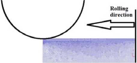
Fig. 1. Roll, clad sheet, ingot and pusher in the first simulation step
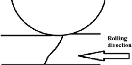
Fig. 2. Neutral section position during high section ingot rolling
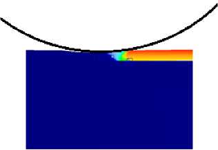
Fig. 3. Speed fields during rolling of ingot with cladding plate: left – cladding plate is not welded to the ingot; right – cladding plate is welded to the ingot
In case ingot is rolled with welded cladding plate, under specific conditions, when deformation does not reach the ingot, the ingot cannot adopt the cladding plate speed on the deformation center exit, in this case either the bond is broken, or cladding plate speed is brought down to the ingot speed (due to their rigid attachment), therefore metal volume per second on the deformation center entry exceeds the metal on the exit side, causing ridge formation on the entry side (Fig. 4).
Such phenomenon causes steady rolling force increase with cladding plate thickness buildup, until max stand drive allowable load is exceeded.
In order to avoid this negative effect, the reduction shall be selected to ensure compression deformation penetration to the ingot. The figures below illustrate the effect of various parameters on deformation penetration into the ingot.

Fig. 4. Ridge picture
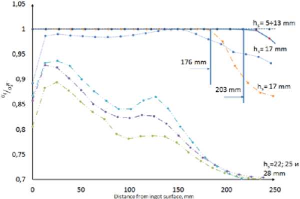
Fig. 5. Plastic deformation penetration depth as the function of cladding plate thickness (reduction 10 mm, rolls diameter 900 mm, package thickness is 526 mm) [6]
The data, presented in Fig. 5, enable evaluating the cladding plate thickness effect on the deformation penetration depth in the ingot. It is obvious, that during high ingot rolling plastic deformation does not penetrate the entire ingot section, and its middle section is left intact (solid line in the diagram shows the results of modelling ingot rolling without clad material). In the case of 5-13 mm cladding plate application, plastic deformation penetrates the entire ingot thickness, but further cladding plate thickness increase results in the ingot plastic zone reduction and vanishing. With cladding plate thickness of 17 mm and over stress intensity - yield strength ratio (a i /a, s ) along the entire ingot section is below 1, therefore, plastic deformation does not occur in the ingot during the first pass. The cladding plate itself is significantly deformed (at constant reduction value the clad plate deformation level is in direct proportion to the cladding plate thickness). Such scenario causes extensive cladding plate elongation, see Fig. 6.
As follows from the diagram below (Fig. 8), reduction increase does not produce the desired effect, deformation penetrates into the ingot at 25 mm reductions only.

Fig. 6. Excessive cladding plate deformation
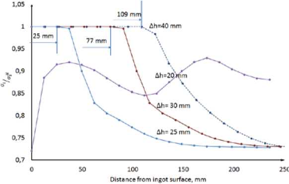
Fig. 7 ’Ч„ -
variable change depending on reduction value (ingot thickness 470 mm, cladding plate thickness
28 mm, roll diameter 900 mm)
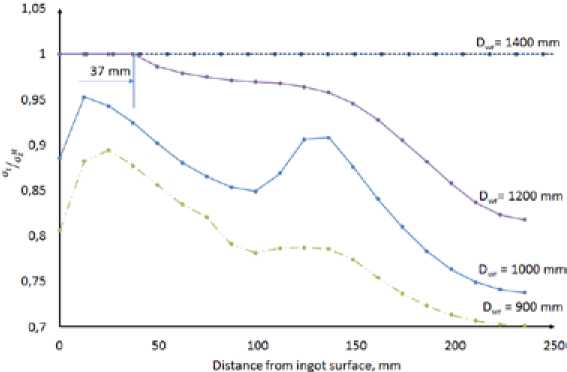
Fig. 8. ^
variable change as the function of work rolls diameter
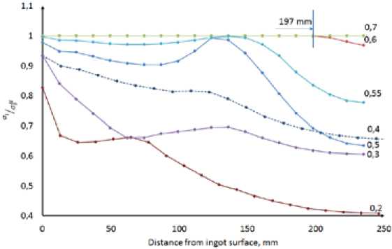
Fig. 9. °Ч „н variable change depending on ° s / „н as / O's
It is known, that work roll diameter increase facilitates deformation penetration into the ingot [7].
Fig. 9 shows deformation penetration into the ingot as function of roll diameter variability. It is seen from the diagram, that plastic deformation penetrates into the ingot (470 mm thick with up to 28 mm thick cladding plate) with roll diameter of 1200 mm, and passes through the section with 1400 mm diameter.
Another variable of interest is
о/ the cladding plate yield strength / ingot yield strength s / н (see °s
Fig. 9), in case 2XXX, 5XXX, 7XXX type hard alloys are rolled at 400 0С this ratio may vary within
0,3÷0,4 range.
Conclusion
The study covers the effect of the main rolling parameters on compression deformation penetration through the ingot section.
The min required reduction value of 25 mm is established for metal clad ingot rolling (as scalped ^м thickness is 470 mm, clad plate is 28 mm), with °т /у.т=0,4 ratio and 900 mm roll diameter.
To ensure deformation penetration into the ingot, it is recommended to use rolling mills with 1200-1400 mm diameter rolls for rolling the ingots with cladding plates thickness over 20 mm.
References Large size metal-clad ingots rolling process analysis using finite elements method
- Колпашников А.И., Арефьев Б.А., Мануйлов В.Ф. Деформирование композиционных материалов. М.: Металлургия, 1982, 248 с.
- Король В.К., Гильденгорн М.С. Основы технологии производства многослойных металлов. М.: Металлургия, 1970, 236 с.
- Кобелев А.Г., Потапов И.Н.,. Кузнецов Е.В. Технология слоистых металлов. М.: Металлургия. 1991, 248 с.
- Пучкова Л.М. Особенности совместной прокатки высоких слоистых полос разнопрочных металлов. Производство Проката, 2014, 9, 3-10
- Грудев А.П. Технология прокатного производства. Учебник для вузов. М.: Металлургия, 1994. 656 с.
- Яшин В.В., Беглов Э.Д., Арышенский Е.В., Латушкин И.А. Влияние толщины плакирующего слоя на распределение деформации по сечению слитка. IХ Международный Конгресс «Цветные металлы и минералы-2017». Красноярск, 2017, 735-744
- Орлов В.К., Дрозд В.Г., Сарафанов М.А. Особенности прокатки плит из алюминиевых сплавов. Производство проката, 2016, 4, 11-16
