Local stability of an elastic beam in a medium with constant resistance

Author: Smirnov P.N.
Journal: Siberian Aerospace Journal @vestnik-sibsau-en
Section: Informatics, computer technology and management
Article in issue: 1 vol.27, 2026.
Free access
This article deals with the analysis of the deformed shape of local stability loss of a reinforced flexible beam, occurring due to constrained expansion during heating. The multiple elastic supports of the beam modeled as an elastic medium, which provides constant resistance to both longitudinal and transverse displacements of the rod. The infinitely long beam divided into a buckling region and an adjacent region under compression. The lengths of these regions are unknown and should be determined during the solution process. A part of the potential energy accumulated during compression is expended on the work of internal forces during bending deformation following the loss of stability. This leads to a reduction in the magnitude of the compressive force in the buckled region. The problem of determining the displacement functions and the critical value of the safe heating temperature is formulated as a system of nonlinear differential equations concerning the deformations in the regions of the flexible beam. The solution obtained using the finite difference method, which transforms a system of differential equations into a system of linear algebraic equations. This system takes the closed form with boundary conditions and transversality conditions. A sufficient number of grid nodes for constructing the difference scheme determined through an iterative procedure that compares two adjacent solutions. The criterion for comparison of solutions is a tuple of areas under the graphs of the sought functions, which are calculated through numerical integration using the trapezoidal rule. The obtained final solution compared with the classical solution to the stability problem of an evenly loaded beam, which does not take into account longitudinal displacements. Additionally, it is contrasted with the known solution in the field of operation of continuously welded railway tracks, which also disregards resistance to longitudinal displacements in the buckled region. The refined results obtained by the proposed modified method for calculation of the parameters of the deformed shape of a flexible beam is important for monitoring the pre-critical state of the modelling system.
Local loss of stability, beam in an elastic medium, nonlinear deformations, finite difference method
Short address: https://sciup.org/148333271
IDR: 148333271 | UDC: 539.3 | DOI: 10.31772/2712-8970-2026-27-1-82-94
Text of the scientific article Local stability of an elastic beam in a medium with constant resistance
The use of beam models is a relevant method for solving engineering problems. Their advantage is a high degree of correspondence between exact and numerical solutions, relative simplicity of modeling, solving, and presenting results in problems of determining the stress-strain state. A separate class of problems consists of supported beams, i.e., beams having multiple supports. Strictly speaking, the modeling of such objects should be performed with discrete reinforcement [1; 2]. But with a large number of closely spaced supports, the reinforcement can be modeled as a distributed load acting along the entire length of the beam. In the latter case, we can speak of beams on an elastic foundation or in an elastic medium. The stability problem of such a beam under compressive forces in a linear deformation-based formulation was considered in [3]. Deformations thereby occur along the entire length of the beam.
The phenomenon of local buckling of structural elements is observed in many fields of engineering [4; 5]. Under certain loads and constraints, a qualitative change in the nature of deformation occurs not over the entire length or surface of the body under consideration, but only in a small part of it. A mathematically equivalent problem is the problem of thermal buckling of a long railway track. When expansion is restricted due to heating, a compressive force arises in the rails, which can lead to buckling. The most complete solution to such a problem was first obtained by A. Kerr [6–8]. While solving the problem of determining the safe heating temperature of a railway track, he obtained relationships linking the transverse displacements of a straight flexible beam with the heating temperature and compressive force.
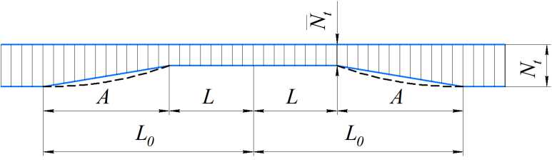
The first deformed shape of the flexible beam is shown in Fig. 1.
The x -axis is directed along the axis of the undeformed beam. The problem is symmetrical; the beam is divided into two sections: on one of them, the buckling section of length L , both longitudinal and transverse displacements of the beam's cross-sections occur, while on the other, adjacent section of length A , only compression occurs. A characteristic feature of Kerr's problem statement is the consideration of the reduction in the magnitude of the compressive force after buckling, while the lengths of the flexible beam sections where deformation occurs are unknown. The author proposes an exact solution to the problem as a solution to a closed system of differential equations and refers to other researchers who solve a similar problem using approximate methods. Further research in this area takes into account various modeling of connections in the rail-sleeper grid and the resistance of the ballast prism [9–15]. Geometric nonlinearity and dynamic components of transverse load are also considered, in addition to compressive forces [16–21] and accumulated elastic deformations [22; 23]. However, these studies are primarily conducted using numerical methods with applied CAE software or by modeling custom finite elements. The disadvantage of this approach to solving the problem is the inability to analyse the deformed shape of a straight beam, since under axial compression a straight beam remains straight. To qualitatively change the deformation, artificial methods must be used: introducing local irregularities into the beam model or non-uniformities into its resistance model.

Рис. 1 Деформированная форма гибкого стержня
-
Fig. 1. Deformed shape of a flexible beam
In the well-known solution [7; 8] to the problem under consideration, the following assumptions are used. Longitudinal and transverse resistances to relative displacement in the rail-sleeper grid connection are considered perfectly rigid and resistance to rotation is disregarded. Then the railsleeper grid is replaced by an equivalent beam with corresponding cross-sectional characteristics, and resistance is understood as the resistance in the relative displacement of supports and the base. Resistance to longitudinal displacement in the section with transverse displacements is insignificant and can be neglected. This leads to a constant compressive force in the section. The magnitude of the longitudinal and transverse resistances is constant. The relationship between heating temperature and transverse displacements is not unique, due to the existence of an unstable equilibrium branch of the deformed shape. This leads to the following form of solution: all parameters of the deformed shape are expressed in terms of the magnitude of the compressive force in the buckling section. Assuming a certain value for this force, we obtain solutions for the functions of longitudinal and transverse displacements of the beam's cross-sections. And varying force values within a reasonable range makes it possible to obtain a relationship between the maximum transverse displacements and the compressive force or the beam's heating temperature.
Problem Statement
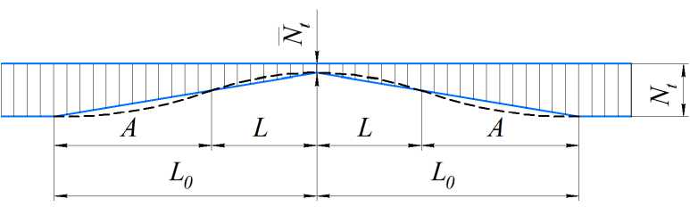
In this work, a modification of the original solution from [7; 8] is proposed, taking into account resistances on all sections of the flexible beam (Fig. 2). When expansion is restricted due to temperature, a compressive force N t arises in the beam. In the local buckling region, this compressive force decreases after the beam's deformation and assumes the value N t . Fig. 2, а shows a graph of the change in compressive force in the case when longitudinal resistance in the section with transverse displacements is neglected [7]. Figure 2, б shows the graph of the change in compressive force, taking into account longitudinal resistance in all sections. The magnitude of the force N t is a parameter, by varying which we obtain solutions. The graphs in Fig. 2 are schematic, the value A is much greater than the value L , and the compressive force, strictly speaking, changes non-linearly.
б
Рис. 2. Сжимающие силы на участке локальной потери устойчивости:
а – пренебрежение сопротивлением продольным перемещения на участке выпучивания;
б – учет сопротивления продольным перемещениям на участке выпучивания
-
Fig. 2. Compressive forces in the area of local loss of stability:
-
a – neglecting of the resistance to longitudinal displacement in the buckling region;
б – taking into account the resistance to longitudinal displacement in the buckling region
The system of equations describing the deformed shape of a flexible beam in the local buckling region, taking into account variable resistance, is as follows:
(EJv[)"-( EF (sl-aT) v L )'=-p;
• (EF (sl-aT ))=- r;
( EF(S A-aT ))' =- r, where
s n
= U n + 2 ( V n ) , n = A, L
deformations in the section; u n = u n ( x ) – longitudinal
displacements in the section; vn = vn (x) - transverse displacements in the section; p - resistance to transverse displacements; r – resistance to longitudinal displacements; E – Young's modulus; J – axial moment of inertia of the cross-section of the equivalent beam; F – cross-sectional area of the equivalent beam; a - coefficient of linear thermal expansion; T - heating temperature. Deformation eL refers to a section with longitudinal and transverse displacements, deformation eA - to a section without transverse displacements. All differentiation operations are performed with respect to the variable x.
Considering the graph of the compressive force in Fig. 2, б , the first integral of the second equation in (1) can be written as
EF(eL - aT) = -Nt - rx.
Then, taking into account the expression for deformations and the fact that in the section without transverse displacements vA = 0, we rewrite the system of equations (1) with respect to displacements u and v :
( EJvL) ’+(( N + rx) vL )'=-p;
EF [ u L + 1 ( v L ) 2 —a T jj =- r ;
(EF(uA -aT)) =-r.
Numerical implementation
Let's expand the parentheses in the first equation of system (2):
v"l +
( N t + rx ) v -+ -L v i—P- EJ L EJ L EJ
We will convert the continuous system into a discrete one using the finite difference method. We apply a uniform grid with n nodes to the segment L . To approximate the derivatives of transverse displacement using finite difference schemes, we will choose a five-point stencil. We replace the values of the derivatives at the grid nodes with their discrete analogs:
vL =
( v L ) j +1 -( v L ) j -1
2 h
v L =
vL"=
vL =
( v L ) j +1 - 2 ( v L ) j + ( v L ) j -1 h 2
( v L ) j +2 - 2 ( v L ) j +1 + 2 ( v L ) j -1 -( v L ) j -2 2 h 3
( v L ) j +2 - 4 ( v L ) j +1 + 6 ( v L ) j - 4 ( v L ) j -1 + ( v L ) j -2 h 4
where h = L /( n – 1) – the step of a uniform grid. Substituting these expressions into (3), after transformations, we obtain a difference scheme for calculating the transverse displacements of sections of a flexible beam:
( vL U
+
' h 2 ( N + rx j
\
EJ
) h3 r - +
2 EJ
^^^^B
4 ( v L ) j +1
/
+
' h 2 ( N t + rx j
\
+ 6
\
^^^^B
2 h 2 ( Nt + rx j )
EJ
( vL ) j +
/
\
EJ
1-hr - 4 ( Vl )
2 EJ V
^^^^B
/
J -1
+ ( vL )
' J -2
^^^^B
h 4p
EJ
.
Writing such equations for all grid points, we obtain a system of n equations, which include n +4 unknown displacements at the nodes. Extra unknowns are the displacements of nodes beyond the contour, which appear when writing equations (5) at the nodes on the boundary of the beam contour. Let's write the boundary conditions for the transverse displacement function on section L :
v L ( 0 ) = 0; v'[( 0 ) = 0; v l ( L ) = 0; v L ( L ) = 0. (6)
In the stability problem formulation under consideration, the lengths of neither the entire flexible beam nor its sections are known. Then, to complete the solution, one must add the transversality equation – the condition that the end of the deformed shape of the beam in the considered section lies on a line coinciding with the x-axis:
v L ( L ) = 0.
Now, let's expand the brackets in the remaining two equations (2):
UL + vL vL =
r
. EF
U A =
r
. EF
In this system, each equation describes longitudinal displacements on a single section of the beam. When constructing a difference scheme, a separate grid is built on each of the sections (Fig. 3). The number of nodes in each grid is the same, the segment lengths are different, and, accordingly, the grid steps are also different. When writing difference equations at each grid point, independent ghost nodes appear in each of the sections.
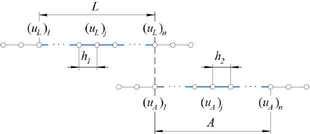
Рис. 3. Равномерные сетки на участках гибкого стержня
Fig. 3. Uniform grids on the flexible beam regions
Let's consider this system as equations only with respect to longitudinal displacements u and replace the corresponding derivatives with finite difference analogs:
( ul ) j+i- 2 ( ul ) j + ( ul ) j-i = -(vL) j (vL) j h?- Ef , ( UA )J+1 - 2 ( UA )J + ( UA )J-1 =- Er,
where h 1 = h – grid step in the buckling region, h 2 = A /( n – 1) – grid step in the adjacent region. Boundary conditions for the function of longitudinal displacements consist of conditions at the ends of the beam and section coupling conditions:
uL (0) = 0; uA (L0 ) = 0; uL (L) = uA (L); uL (L) = uA (L) •
To complete the solution, we will add the condition that the end of the deformed shape of the beam lies on a line coinciding with the x-axis.
u A ( L 0 ) = 0 •
Now the problem of calculating the displacements of a flexible beam's cross-section for a given compressive force reduces to the problem of solving a system of linear algebraic equations C·w = b.
Here
C =
' C v
I 0
0 ^
C u )
is a block matrix, consisting of the matrix Cv of coefficients for transverse
displacements v , which includes equations (5), written for all nodes of the first section together with boundary conditions (6) and (7), and the matrix Cu of coefficients for longitudinal displacements u , consisting of equations (8), written for all grid nodes on both sections of the beam, together with boundary conditions (9) and (10). w = ( v ; u )T is the vector of beam cross-section displacements, consisting of displacements v = vL and u = ( uL ; uA )T. b = ( bv ; bu )T is the vector of free terms, consisting of the vector b v of the right-hand sides of equations with respect to v and the vector b u of the righthand sides of equations with respect to u . Finally, we can write
C v
\
0 v
Cu J u }
th \ \ bu у
The block form of matrix C allows for the calculation of transverse displacements in the buckling region v independently of the rest of the model by solving the system of equations Cv · v = bv . From the value of the function v j at the grid nodes, it is also possible to calculate the values of the derivatives of this function at the nodes, which, when substituted into (8), allow obtaining the values of longitudinal displacements ( uA ) j and ( uL ) j at the grid nodes by solving the system Cu · u = bu .
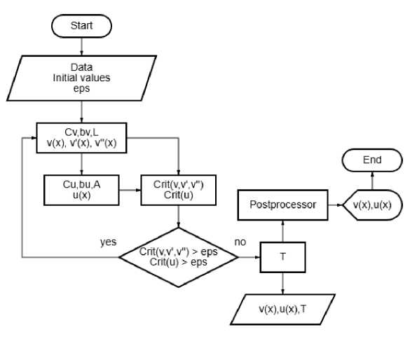
Рис. 4. Блок-схема решателя
Fig. 4. Resolvent flowchart
A sufficient number of mesh nodes is determined by comparing two adjacent solutions. The number of nodes n in the finite difference approximation template is taken as the initial approximation. If the relative difference in areas under the graphs of functions of adjacent solutions does not exceed a predetermined value ε , the iterative process of finding a sufficient number of nodes stops. Otherwise, the number of grid nodes increases by the number of nodes in the difference stencil. Function values between adjacent values at the nodes are determined by linear interpolation. The area under the graph is calculated using numerical integration with the trapezoidal rule. This criterion is calculated for the functions of transverse displacement v and longitudinal displacement u . And also for the first and second derivative of the function v . The flowchart of the algorithm for calculating displacement functions is shown in Fig. 4.
Calculation Results
The calculation was performed in a computer algebra system using equivalent beam parameters from works [7; 8], converted to SI units: E = 2,06·105 MPa, J = 8,99·106 mm4, F = 1,45·104 mm2, α = 1,05·10–5 °C–1, ρ = 5,886 N/mm, r = 9,81 N/mm. Algorithm termination value ε = 0.001. Comparison of calculation results for the smallest compressive force value in the buckling section Nt = 882.9 kN is presented in Table 1. Calculation number 1 – solution without longitudinal displacements from [3], calculation number 2 – solution without considering longitudinal resistance in the buckling section from [7], calculation number 3 – solution considering longitudinal resistances in all sections of the deformed beam. Longitudinal displacements in calculation 1 are undefined (value "n/a" in tables), there is no section without transverse displacements in the model. The length of the buckling section obtained in calculation 3 is adopted as the design length of the beam, which must be known in advance.
Table 1
Calculation results of the parameters of the deformed shape at N̅t = 882.9 kN
|
Settlement number |
Heating temperature T , °C |
Section length L , m |
Section length A , m |
Maximum transverse displacements v , mm |
Maximum longitudinal displacements u , mm |
|
1 |
28,15 |
6,423 |
N/A |
219,68 |
N/A |
|
2 |
43,69 |
6,502 |
51,447 |
219,41 |
4,23 |
|
3 |
44,61 |
6,424 |
47,605 |
205,88 |
3,67 |
Analysis of the results in Table 1 shows that the transverse displacements in calculations 1 and 2 are very close, the difference between them is 0.12%. When calculation 1 uses twice the length of section L from calculation 2 as the design length of the beam, they become even closer and the difference between them decreases to 0.06%. The largest transverse displacements will then be 219.54 mm. However, the safe heating temperature in calculation 1 is underestimated compared to the results of calculations that account for the longitudinal displacements of the beam's cross-sections. Refined calculation 3 shows lower longitudinal and transverse displacements of the beam's cross-sections compared to the known solution of calculation 2. In this case, the heating temperature value turns out to be higher. Table 2 presents a comparison of calculation results for a temperature of T = 50 °C.
Calculation 1 shows unsatisfactory results for the supercritical region. In addition to a very large value of compressive force, the deformed shape contains several half-waves. Calculation 3 shows smaller deformations compared to Calculation 2. But there is a greater drop in compressive force at smaller displacements of the flexible beam sections.
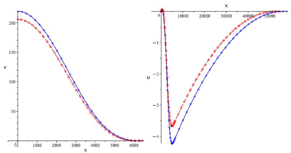
Graphs of transverse and longitudinal displacements of flexible beam sections for a compressive force of N t = 882.9 kN are shown in Fig. 5. The solid blue line shows displacement functions obtained in calculation 2, the dashed red line – functions from calculation 3.
а б
Рис. 5. Функции перемещения в расчетах 2 и 3 при сжимающей силе Nt = 882,9 кN: а – поперечные перемещения v ; б – продольные перемещения u
Fig. 5. Displacement functions in solutions 2 and 3 under compressive force N t = 882,9 kN: а – lateral displacement v ; б – longitudinal displacement u
а б
Рис. 6. Зависимости сжимающей силы на участке выпучивания и температуры нагрева от наибольших поперечных перемещений:
а – сжимающая сила N t ( v max ); б – температура нагрева T ( v max )
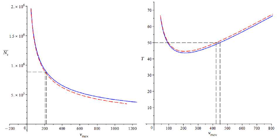
Fig. 6. Compressive force in the buckling region and the heating temperature as functions of the largest lateral displacement:
а – compressive force Nt ( v max); б – heating temperature T ( v max)
Results of calculation of deformed shape parameters at T = 50 °C
Table 2
|
Settlement number |
Compressive force on section L N̅ t , kN |
Section length L , m |
Section length A , m |
Maximum transverse displacements v , mm |
Maximum longitudinal displacements u , mm |
|
1 |
1568,25 |
6,994 |
N/A |
443,29 |
N/A |
|
2 |
617,05 |
7,777 |
100,427 |
449,19 |
15,81 |
|
3 |
602,19 |
7,709 |
93,526 |
422,15 |
13,88 |
Graphs showing the relationship between the maximum transverse displacements of the beam and the magnitude of the compressive force Nt in the center of the deformed region, and the heating temperature T are presented in Fig. 6.
Conclusion
An approach to solving the thermal stability problem of a reinforced flexible beam is considered. The advantage of the proposed solution is the consideration of resistance to longitudinal displacement across all sections of the beam. Analysis of the results presented in Tables 1 and 2, as well as in Fig. 5 and 6, shows that the refined solution gives a higher value for the safe heating temperature, as well as a greater drop in compressive force in the buckling zone at the same temperature. Refinement of the magnitude of displacements of the beam's cross-sections upon buckling is important for monitoring the pre-critical state. It can also be noted that the classical solution to the problem of beam stability loss in [3], which does not account for longitudinal displacements and the decrease in compressive force in the buckling zone, gives unsatisfactory results. The reduction in the magnitude of the compressive force, which occurs due to the expenditure of part of the potential energy accumulated during compression on the bending of a flexible beam after buckling, has a significant influence on the magnitude of deformations and the critical temperature. Further development of the proposed approach is envisioned by taking into account the nonlinear nature of the elastic foundation's resistances to longitudinal and transverse displacements. And also obtaining similar solutions for the following forms of instability. In addition to the symmetric form discussed, the asymmetric form and forms with a large number of half-waves are of practical importance.
