Loudspeaker operation status monitoring system based on power line communication technology

Author: Biyue Diao, Guoping Chen, Feng He
Journal: International Journal of Image, Graphics and Signal Processing @ijigsp
Article in issue: 10 vol.10, 2018.
Free access
With the rapid development of science and technology, intelligent systems have been applied to various fields. A monitoring system for the operating status of loudspeakers based on power line communication was designed and implemented. In this paper, firstly analyzes the deficiencies of previous research, and then according to the actual situation, it is concluded that the power line communication technology is more suitable for loudspeaker operating status monitoring than other communication technologies. The overall design, hardware design and software design of the entire system was introduced. And in the last, the reliability of the system were proved by many experiments. This system can be used in other applications in addition to the monitoring of the operating status of the loudspeakers.
Power Line Communications, Loudspeakers, Monitoring
Short address: https://sciup.org/15016004
IDR: 15016004 | DOI: 10.5815/ijigsp.2018.10.06
Text of the scientific article Loudspeaker operation status monitoring system based on power line communication technology
Published Online October 2018 in MECS
As a very important electronic system in modern large-scale buildings, the public broadcasting system has been widely used in various fields. The public broadcasting system mainly providing a series of information transmission functions. When large natural disasters such as earthquakes and tsunamis occur, in order to respond to the sudden dangers quickly and evacuate people in a timely manner to ensure the safety of everyone's lives, the protection of loudspeaker terminal operation reliability of the public broadcasting system is particularly important.
Loudspeaker also refers to the "horn" in daily life. It is a basic electro-acoustic conversion device, which can convert electrical energy into mechanical energy. A key part of loudspeaker quality detection is listening test. At present, there are two detection methods, physical measurement method, and human ear detection method. Listening test, as its name implies, depends on the subjective judgment of human hearing to determine whether there is a fault in the loudspeaker. The auditor’s hearing is affected by external influences, emotions, physical conditions, the test results are uncertain, and long-term listening to human ears is also harmed to auditors’ auditory systems [1]. Although we all know that this method has many flaws, and a lot of research has been done on the automatic detection of speakers, but still cannot find a detection method that can replace the human ear detection. So, to ensure the loudspeaker's production quality better, the detection method that is widely used is still a traditional manual detection.
Through the above analysis, it is particularly important to design a system for monitoring the operating status of loudspeakers. The widely used monitoring technologies that do not need to re-establish communication lines include wireless communication technologies and power line communication technologies. The widely used wireless communication technologies mainly include Bluetooth, Wi-Fi, ZigBee and so on [2]. Wireless communication technology has the advantages of low cost, good adaptability, and easier maintenance of equipment, etc. However, the short communication distance and the lack of penetrating power limited its application to loudspeaker status monitoring. Power line communication technology has high reliability and economy. Therefore, a loudspeaker operating status monitoring system based on power line communication technology was proposed.
This paper presents an easy-to-install, high-reliability monitoring system design. The rest of this paper is organized as follows: The second part describes the previous work of the speaker operating condition monitoring system, and the third part describes the design of the overall solution. The fourth part and the fifth part respectively introduce the specific implementation method and function test of the system and draw conclusions in the sixth part of the article.
-
II. Related Work
In the process of the development of public broadcasting systems, the loudspeaker operation status monitoring system is not independent of the development of the broadcasting system itself, but a device with state self-checking function module that appears with the continuous enrichment of the broadcasting system function, which usually includes a speaker state monitoring device, data communication and system power supply three parts.
Although the cable public broadcasting system has been continuously improved with the development of science and technology and its functions are more abundant, its most basic functional modules are still source equipment, power amplifier, signal processing unit, audio signal transmission line network and speaker terminal. In order to meet various practical needs, the functions of public broadcasting systems have also diversified. Take the products of DSPPA as an example. The first generation public broadcasting system had a simple structure and a single function. It relied on a simple timing control device to automatically play scheduled music, and can only complete automatic music playback and drive early warning alarms. With the maturity of computer technology, the second generation public broadcasting system added the PC as the central control terminal, and the operation is simple and convenient. The third-generation public address system focuses on the development of addressable systems, which reduce the material consumption of the transmission line and improves the transmission effect; now the fourth generation of products are used in PC applications. It is more intelligent, stable and efficient, with background music playback, information release, emergency broadcast, danger alarm and status self-test.
BOSCH of Germany is one of the earliest companies engaged in the development, design, and sales of public broadcasting systems in the world. Over the past halfcentury, it has continuously developed excellent broadcast and broadcast management systems. Ten years ago, it launched the most modern modular CPU to control public Broadcast system. The most advanced speaker broadcast management system on the market today is BOSCH's digital broadcast system, Praesideo Audio Microcomputer Management System. The system has two major functions, broadcast management and fault monitoring [3]. Based on the distance between devices, the system uses two fiber cores to process and communicate audio signals and control signals. A group of copper pairs provides power for terminal equipment. If the transmission distance is too long, the equipment in the system is powered by the local power supply. The broadcasting system is fully functional and can satisfy most users' needs. However, it is necessary to use active terminals, and the system must be installed with additional power lines.
Guangzhou Meidian Bell Electric Technology Company developed a speaker fault monitoring device in 2013, which connected the current-sensing resistor and current detection module into the front end of the loudspeaker of the broadcasting system. It detected the current and voltage on the transmission line of the loudspeaker through the control of microprocessor module. The analog-to-digital converter samples its value to determine if the loudspeaker is working properly or not. The speaker detection device can only detect the open circuit and short circuit conditions of the loudspeaker front end in the broadcasting system, cannot monitor the damage of the loudspeaker itself, the detection function is not complete, and the detection data aggregation function is not available. So, the device can’t satisfy the demand.
In 2015, BOSCH introduced a loudspeaker test board for monitoring the integrity of loudspeakers. The device is powered and communicated through existing loudspeaker terminal cables, enabling fault detection without additional wiring. However, the device still cannot detect whether the loudspeaker is in a normal state or not and cannot operate independently, either. So, the application has limitations.
-
III. The Overall Design
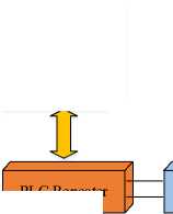
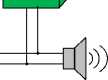
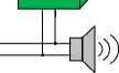
This section describes the design of the overall architecture of the system. The overall block diagram of the system is shown in Fig. 1.
As shown in the figure, the PLC (Power line communication) repeater controls power amplifiers to power the nodes and send the signal to be detected at a frequency of 100Hz. The nodes transmit the collected loudspeaker operation status data via the audio cable to the PLC repeater. And then, the PLC repeater translates the data to the computer through the network cable.
-
A. Power line communication
With the development of signal technology, the advantages of low-voltage power line communication technology and the great application prospects gradually emerged [4]. Power line communication is a unique communication method for the power system. It uses the power line as the transmission medium to couple high-frequency carrier signals to the line and uses the line to transfer digital information. Once the information is transmitted to the user, then use the modem to separate the transmitted signal. This technology has reached a relatively mature level and has been widely used in power production, power grid management, economic dispatch and other fields.

Power Amplifier
PLC Repeater

Node5

Node2
Node1

Node7
('(<И1=
/ и
Node4

Node3

Node6

Node8
^^ Network Cable
Audio Line
Fig.1. The overall block diagram.
The technology was first applied to the above high-voltage lines, and the geographical coverage can be very wide. High-voltage lines as a communications medium originated in 1920 [5]. At that time, the coverage of the telephone network was limited. Engineers used PLC as the communication method to communicate with power plants and substations in dozens or hundreds of kilometers away. With the rise of digital communication technology, low-speed PLC technology has also been used to support telemetry and remote control applications. Because of the demand for communication speed, the European CENELEC organization issued the EN50065 standard in 1992. The frequency spectrum specification for 3 kHz to 149.5 kHz was developed for narrowband PLC technology. It was divided into A, B, C, D and other frequency bands. Its main applications are low voltage distribution network control and power consumption information acquisition.
With the development of communication technologies, technologies developed based on FSK (Frequency-shift keying) or BPSK (Binary Phase Shift Keying) have been gradually replaced by more advanced modulation technology OFDM (Orthogonal Frequency Division Multiplexing). OFDM technology has a reliable working mode, efficient channel coding technology, and a powerful error correction mechanism. It is the most cost- effective and secure communication mode in today's smart grids. G3-PLC is the power line communication standard based on OFDM modulation and demodulation technology[6]. G3-PLC is a global open protocol of power line communication, which is specially designed for smart grid communication. It was initiated by the French power transmission company and developed jointly by Maxim and Sagem Communications.
G3-PLC belongs to the Narrow-Band Power Line Communications (NB-PLC) standard that has gained prominence over the last few years [7]. And it is commonly used in low-speed data communication applications such as automatic meter reading (AMR), energy control, and power grid monitoring [8]. G3-PLC belongs to the Narrow-Band Power Line Communications standard and is commonly used in lowspeed data communication applications such as automatic meter reading, energy control, and power grid monitoring [9]. In addition, G3-PLC has higher reliability during data transmission. The loudspeaker operation status monitoring system was based on G3-PLC technology.
-
B. Internet Protocol Version 6(IPv6)
G3-PLC divides the protocol stack into five layers: the physical layer, MAC layer, network layer, transport layer, and application layer. In order to ensure the long-term continuity of the system, the Internet Protocol Version 6 (IPv6) was adopted in the network layer.
IPv6 addresses are divided into unicast addresses, multicast addresses, and anycast addresses [10]. The unicast address is used to uniquely identify an interface, similar to a unicast address in IPv4. Datagrams sent to a unicast address will be transmitted to one of the interfaces identified by this address. The multicast address is used to identify a group of interfaces, similar to the multicast address in IPv4. The data message sent to the multicast address is transmitted to all the interfaces identified by this address. The anycast address is used to identify a set of interfaces. The data message sent to the anycast address is transmitted to the nearest interface to the source node in the set of interfaces identified by this address [11]. In the system, the unicast address was adopted.
The basic header length of an IPv6 packet is fixed at 40 bytes and includes a total of 8 fields, removing all options in the IPv4 header. The specific format of the IPv6 protocol packet is shown in Fig.2.
-
1) Version indicates the version number of the IP protocol corresponding to the data packet, the version number of IPv4 is 4, and the version number of IPv6 is fixed at 6.
-
2) Traffic Class can give different priority to data packets, and providing different services helps to improve QoS(Quality of Service);
-
3) Flow label is a new field of IPv6. The source node uses this field to identify the data packet of the same flow.
-
4) Payload Length indicates the total length of packets except the basic header, including the number of bytes occupied by all the extension headers and upper layer PDU (Protocol Data Unit) data.
-
5) Next Header forms an extended header chain. This field indicates whether this IPv6 packet contains an extension header.
-
6) Hop Limit This field replaces the TTL field of the IPv4 protocol.
-
7) Source address identifies the IPv6 address of the source node that sent the packet.
-
8) Destination address identifies the IPv6 address of the destination node that received the packet.
-
9) The IPv6 protocol discards the option fields in IPv4 when it is designed, and uses the extension header method to meet the special requirements of different data packets.
|
Version |
Class |
Flow Lable |
||
|
Payload Length |
Next Header |
Hop Limit |
||
|
Source Address(16 bytes) |
||||
|
Destination Address(16 bytes) |
||||
|
Possible Extension Header |
||||
|
Payload |
||||
Fig.2. IPv6 protocol packet
-
C. Sound sensor
The sound sensor is a device which is used to detect whether the loudspeaker is working properly or not in the system. The sound sensor is as shown in Fig.3.
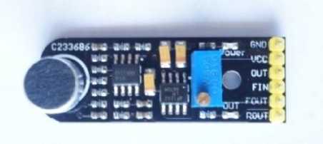
Fig.3. The sound sensor module
The sound sensor collects sound signals through electret condenser microphone. The pin diagram of phase locked loop detection module is as shown in Fig.4.
The sound signal is first converted into an electrical signal, amplified by the LM358 amplifier, and then send to the LM567 phase lock detection module. The phase-locked loop detection module compares the frequency of the input signal with the previously set frequency and outputs the switch signal. Equation 1 shows how the center frequency is calculated.
1.1 RC
The capacitance is a fixed value and the resistance is a sliding rheostat. So, the threshold of the frequency can be set by adjusting the resistance of the PLL detection module.
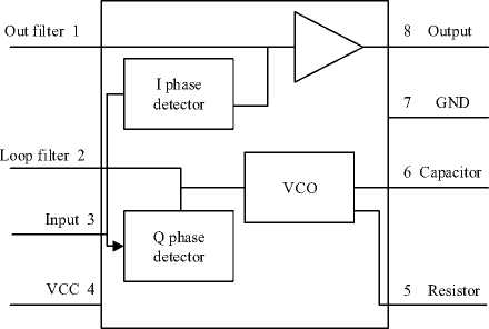
Fig.4. Phase locked loop detection module
-
IV. System Specific Implementation
The specific implementation of the system includes hardware implementation and software implementation. The section will introduce the implementation in detail.
-
A. Hardware implementation
The hardware implementation includes the hardware implementation of data concentrator module and data collection module.
-
1) Data Concentrator Module
MCU (Microcontroller Unit) 1 is the main MCU, TMS320F28PLC84 which was launched by TI plays the role of MCU1. MCU2 is the secondary MCU, TM4C1294 acts as MCU2.On one hand, the secondary MCU will help the main MCU to configure G3 network and to send or receive PLC data. The other hand, the secondary MCU will control the MSP430169 to send a sinusoidal signal with a frequency of 100Hz and amplitude of 2.5 volts to the power amplifier and will send the received PLC data to the computer via network cable.
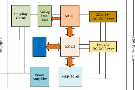
Analog Signal
Fig.5. Block diagram of data concentrator

Digital signal
-
2) Data Collection Module
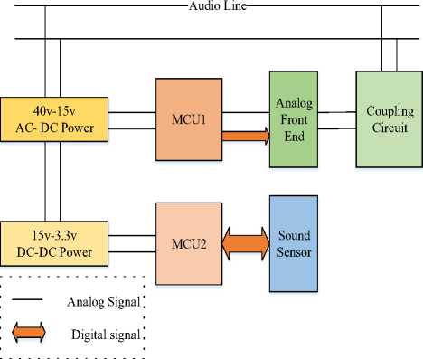
Fig.6. Block diagram of data collection
The above figure shows there are two MCUs, MCU1 is TMS320F28PLC84, and the MCU2 is CC1310. Just like the data concentrator module, MCU1 is the main MCU, MCU2 is the secondary MCU, too. The MCU2 will collect the data which was sent by the sound sensor, and then transmit the data to data contractor via the power line. The MCU2 will also cooperate with the MCU1 to join G3 network and make data transmission.
The coupling circuit is mainly composed of a transformer and a capacitor [12]. A carrier signal is coupled to the power line through a transformer and a capacitor, and a carrier signal is received from the power line at the same time. The transformer not only has the effect of isolation but also can realize impedance transformation.
Analog front-end includes an analog front-end core chip AFE031. The AFE031 is a low-cost, integrated power line communication analog front-end device that can be coupled to a capacitor or converter. The chip suitable for driving low-impedance lines, which can be up to 1.5A injection current to the load reactance while the integrated receiver capable of detecting a minimum 20u VRMS signal and providing a wide range of gain options to accommodate different input signal conditions, to provide a power line communication applications High reliability. The AFE031 transmission power amplifier operates in a single-supply mode from 7V to 24V, while the analog and digital signal circuits are powered from a single 3.3V supply. AFE031 mainly consists of three modules, namely power amplification module, transmission module and receiving module.
-
3) Transmitting circuit
The design of the transmitting circuit is as shown in Fig.7.
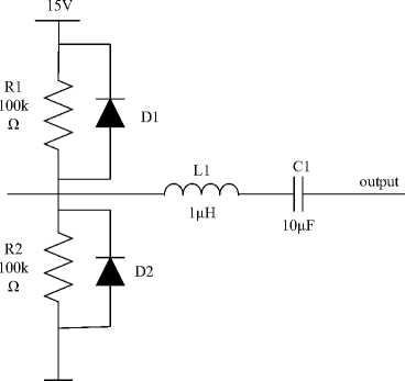
Fig.7. Transmitting circuit
The transmitting circuit can play a protective role and forms a low-pass filter with the input of the coupling circuit to isolate and buffer the PLC modulation signal on the line.
-
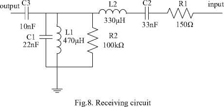
4) Receiving circuit
The receiving circuit is designed as a band-pass filter and the pass-band frequency contains 35-91 kHz which is specified by G3 standard. The design of receiving circuit is as shown in Fig.8.
-
B. Software implementation
Software design is the core of the whole system, it determines whether the system can work properly.
-
1) CCS
The software compile environment is CCS (Code Composer Studio), which is a code development and debugging suite produced by Texas Instruments (TI).
Code Composer Studio includes a comprehensive set of tools for developing and debugging embedded applications. It contains compilers, source code editors, project build environments, debuggers, descriptors, emulators, and a variety of other features for each of the TI device families. And the CCS accelerates and enhances the development process for creating and testing applications [13]. The CCS IDE provides a single user interface that helps developers complete each step of the application development process. With sophisticated and efficient tools, users can quickly get started and add functionality to their applications using familiar tools and interfaces.
-
2) TI-RTOS
This system not only needs to complete real-time data acquisition and processing but also operates for the preservation and communication of data. In order to enhance the stability and scalability of the system and shorten the development time, this article uses proprietary DSP real-time operating system TI-RTOS of TI as a development platform.
TI-RTOS is a complete real-time operating system based on preemptive multi-threading [14], which can significantly speed up software development, eliminating the need for designers to write and maintain complex software programs such as scheduling tools, protocol stacks, and low-level drivers. Developers can easily expand their designs and add functionality by porting legacy applications to the latest processors. It can be downloaded from CCS App Center [15].
-
3) Data Concentrator Software Design
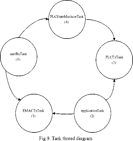
In the data concentrator software part, there are five task thread. Fig.9 shows the diagram of the five task thread.
The following code is the task priority setting program. void uartRxTask_init() {
Task_Params_init(&uartRxTaskParams);
uartRxTaskParams.stackSize = uartRxTaskStackSize;
uartRxTaskParams.priority = 5;
&uartRxTaskParams, NULL);
}
The highest priority is uartRxTask, and it will cooperate with PLCStateMachineTask to establish a G3 network. The PLCTxTask will send data to PLC nodes via power line, and the EMACTxTask will send the data which was received from data collection module to the computer via network cable.The computer will receive data just like the following format.
ff ff ff ff ff ff 30 5a 3a 54 21 16 86 dd 60 00 00 00 00 14 11 0e fe 80 00 00 00 00 00 00 5f ff 00 ff fe 00 00 01 fe 80 00 00 00 00 00 00 5f ff 00 ff fe 00 00 00 62 04 b9 08 00 14 00 00 00 00 00 00 00 05 59 00 00 01 00 01
From the received data, it is clear that which node is in normal operation state.
The above task will be conduct after the BIOS was started. Fig.10 shows the software flowchart of the entire data concentrator.
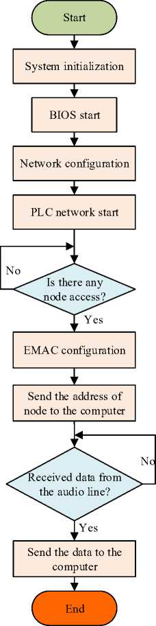
Fig.9. Software flowchart of data concentrator
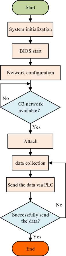
Fig.11. Software flowchart of data collection
-
4) Data Collection Software Design
There are four task threads of data collection software design, uartRxTask, PLCStateMachineTask, PLCTxTask and applicatonTask. Just like the data concentrator design, after initializing the system, the BIOS was started. And then, the uartRxTask will cooperate with PLCStateMachineTask to attach the G3 network which is available. Once attach the network, in the applicationTask ,it will begin to collect the data. In the last, send the data to data concentrator module via PLC in PLCTxTask. Fig.11 shows the software flowchart of data collection.
-
V. Experiments
Many experiments were conducted to verify the reliability of the entire system. There were five loudspeakers installed at different distances from the monitoring center. The experiments test if the data concentrator module can successfully build the G3 network and if the data can be delivered smoothly from data collection module to the computer. The test results are shown in Table 1
Table 1. The results of test
|
node |
Approximate distance(m) |
Times of network start |
Times of network attach |
Times of data received |
|
1 |
100 |
50 |
50 |
50 |
|
2 |
300 |
50 |
50 |
50 |
|
3 |
400 |
50 |
50 |
50 |
|
4 |
600 |
50 |
50 |
50 |
|
5 |
800 |
50 |
50 |
50 |
From the 50 times experiments, it is obviously that the system has high reliability.
-
VI. Conclusion
At the beginning of the article, the related research on loudspeaker operating condition monitoring was analyzed, and the shortcomings of previous research were pointed out. So, a power line communication technology was proposed to achieve the loudspeaker operating condition monitoring. The system is based on the premise that the communication line and the power supply line are not additionally provided, and the operating state of the speaker itself is the object of study. In order to improve the reliability of the system, the power line communication technology adopts the G3 standard with higher reliability. In the software implementation process, the multi-threaded mode of the real-time operating system replaces the interruption mode. This system achieves long-distance communication and high-reliability monitoring through the combined use of software and hardware. And the entire system has practical application value.
References Loudspeaker operation status monitoring system based on power line communication technology
- Zhu Y, Zengpu X U, Ruilin M U, et al. Research on sound fault detection of YDT318-9AU loudspeaker[J]. Audio Engineering, 2016, 40( 7) : 14 - 18.
- Aliyu S, Yusuf A, Abdullahi U, et al. Development of a Low-Cost GSM-Bluetooth Home Automation System[J]. International Journal of Intelligent Systems & Applications, 2017, 8(8):41-50.
- Ying Y M, Pan W M, Xuan C X. Design and Realization of Large Airport Flight Automatic Broadcast System Based on Bosch Praesideo[J]. Computer Era, 2010,(8),69 - 74.
- Xiao-Qi M A. The Development Status and Application Prospect of Power Line Carrier Communication Technology[J]. Mechanical & Electrical Equipment, 2014: 36-40.
- Sun H C, Zhang J B. The Research and Application of the Low Voltage Power Line Carrier Communication[J]. Electrical Measurement & Instrumentation, 2006:139-156.
- Yin J F, Ding W B, Wei H Y, et al. Research on PLC Communication Standards PRIME and G3-PLC[J]. Electrical Measurement & Instrumentation, 2014:37-41.
- Chauvenet C, Etheve G, Sedjai M, et al. G3-PLC based IoT sensor networks for SmartGrid[C]// IEEE International Symposium on Power Line Communications and ITS Applications. IEEE, 2017.
- Hoch M. Comparison of PLC G3 and PRIME[C]// IEEE International Symposium on Power Line Communications and ITS Applications. IEEE, 2011:165-169.
- Zaballos A, Vallejo A, Majoral M, et al. Survey and Performance Comparison of AMR Over PLC Standards[J]. IEEE Transactions on Power Delivery, 2009, 24(2):604-613.
- Ma Q, Yang T. Considerations on IPv6 Address Assignment[J]. 2013: 1-6.
- He Z, Jiang Y, Lu H. IPV6 technology and prospects for development[J]. Electronic Test, 2016:152-153.
- Liu H G, Jiang X J, Xiong W M, et al. Coupling circuit design of power line communication based on DC power[J]. Electronic Design Engineering, 2016,24(14):186-189.
- Prasad S S, Sanyal S K. Design of Arbitrary Waveform Generator based on Direct Digital Synthesis Technique using Code Composer Studio Platform[J]. Applied Mechanics & Materials, 2014, 541-542:466-469.
- YANG Zhen-lun, XU Jiang-xin, YANG Pei-bin. Implement of Io T Gateway Based on TI-RTOS[J]. Modern Computer, 2016:58-61.
- Swathikaa S V, Selvakumar J. Ti RTOS based parking lot guidance system[J]. International Journal of Computer Technology and Applications (IJCTA), 2016: 6165-6173.
