LPA 2D-DOA Estimation for Fast Nonstationary Sources Using New Array Geometry Configuration

Author: AmiraAshour, Yasser Albagory
Journal: International Journal of Computer Network and Information Security(IJCNIS) @ijcnis
Article in issue: 11 vol.5, 2013.
Free access
This paper proposes a new array geometry configuration to improve the two dimensional direction of arrival (2D-DOA) estimation of narrowband moving sources with less complexity. This new array is denoted by verticircular configuration, which is composed of both Uniform linear array (ULA) and Uniform Circular array (UCA) to avoid too much computation for 2D-DOA estimation. The proposed verticircular array is applied with the LPA nonparametric estimator to estimate multiple rapidly moving sources’ parameters (angles and angular velocities) for both azimuth as well as elevation directions. Simulation results show that this nonparametric technique is capable of resolving closely spaced sources provided that their velocities are sufficiently different with decreased computational complexity when using the verticircular array. Different scenarios are used to show the efficient LPA beamformer to distinguish sources that can have the same angles using their different angular velocities. In addition, this paper is to compare the performance of the 2D- LPA DOA estimation algorithm when using verticircular array (proposed array geometry) or rectangular planar array geometry. Simulation results show that the performance of the proposed method with less complexity than that obtained when using rectangular planar array.
Direction of Arrival estimation, 2D-DOA estimation, moving source localization, nonparametric techniques, local polynomial approximation, array geometry, computational load
Short address: https://sciup.org/15011240
IDR: 15011240
Text of the scientific article LPA 2D-DOA Estimation for Fast Nonstationary Sources Using New Array Geometry Configuration
Published Online September 2013 in MECS DOI: 10.5815/ijcnis.2013.11.01
Smart antenna is one of the dynamic research areas in wireless communication systems. The demand for smart antenna increases drastically when dealing with multiuser communication system, which needs to be adaptive, especially in time varying scenarios [1]. Direction of Arrival (DOA) estimation isconsidered as an importanttask in smart antennas. It is an important signal parameter which can be used for source localization or source tracking by determining the desired signal location.
Also, it plays a key role in enhancing the performance of adaptive antenna arrays for wireless communication system and other numerous applications in the field of radar and sonar [2, 3]. Therefore, research has been accomplished about DOA estimation during last recent decades. Various DOA estimation methods have been proposed in [4-10]. These methods differ in technique, speed, computational complexity, accuracy and their dependency on the array structure. Different methods have been suggested to enhance the performance of available algorithms including the increase in the accuracy and resolution of DOA estimation algorithms.
According to the underlying methodology, the array signal processing algorithms can be categorized into two classes. The first class is called the non-parametric approach in which the source locations (or the DOA) are estimated by choosing the strongest output power of aspatial filter after sweeping over the space of interest. The advantage of this approach is that no assumption has to be made on the studied signal. The second class is called the parametricapproach, in which a nominated model is assumed for the array observations. Once the model is determined, the quantities of interest in the array problem can be determined by choosing the best parameters that fit the model under some optimality criteria [11]. Various DOA estimation methods are compared in [12].
In this paper the LPA beamformer will be used as an example for the nonparametric approach as it is able to exploit the structure of studied signal for nonstationary sources. Whereas mentioned in [13], the LPA has better performance than REM (recursive expectation -maximization) algorithms when the DOA parameters change fast. But the drawback for the LPA is its high computational time when compared with REM II due to the two dimensional search procedure required for the LPA beamformer. Consequently, the main goal for the proposed method in this paper is to reduce the computational complexity required for LPA beamformer by using new array geometry.
Where, beside the DOA estimation algorithms, location of the elements in an array is strongly affecting the DOA estimation performance. A considerable work has been done on design of arrays to achieve or optimize the array performance [14]. The investigation of the antenna arrays is often based on Uniform Linear Array (ULA) geometry because of simple analysis and implementation. However, this array geometry has a major drawback where, the ULA is 1-D so it is capable for DOA estimation in one-dimensional applications. Thus, planar arrays, 3-D arrays, and other array geometries are needed to be exploited to resolve today's applications in multi-dimensional DOA estimation.
As 2D- DOA estimation of sources has been a focusing area of researchers since last two decades, the problem of estimating both the azimuth and elevation angles associated with narrow band plane waves using antenna arrays is broadly studied. In [15], planar array is used for 2-D DOA estimation of sources while in [16] two parallel uniform linear arrays have been used. Another various array structures have been investigated; however, L-shaped arrays that consist of two independent uniform linear arrays at right angle to each other are proved to be the simplest structure. Pair-matching between the estimated directions by each ULA represents the main challenging problem. Also, a 2D-array with a V-shape structure, which is suitable for 120 degrees sectorized cellular systems, is proposed. These different types of array structures for smart antennas such as, one L-shape, two L-shape, Y-shaped distribution of elements arrays, and V-shape structure for DOA estimation have been examined in [17-20].
Also, another known geometry structures such as different circular arrangements and hexagonal configuration have been examined for smart antenna applications, but many of these geometries may lead to extra complexity of array structure and additional computations, and the array aperture may become larger. Uniform Circular Arrays (UCA) are of particular importance in DOA estimation since they can provide 360º azimuthally coverage and estimate both azimuth and elevation angles simultaneously. In addition, 2D DOA estimation with UCAs is very useful in practical situations, especially in wireless location [21, 22]. Other DOA estimation algorithms with low computational cost, such as UCA-RB-MUSIC [23], UCA-ESPRIT [23], and uniform circular array rank reduction (UCA-RARE) [24] were developed for stationary sources.
Thus, in this paper it is desirable to develop simple array configuration which performs uniform search in all directions and covers full range of angles with less computation for 2D-DOA estimation for nonstationary sources. Therefore, using both ULA and UCA to take the advantage of simplicity in ULA and the 360º coverage using UCA will provide less computation for 2D-DOA estimation as applied in this paper. Consequently, in this paper a novel simple verticircular array is introduced to overcome the more calculations drawback and to alleviate the computational overhead for fast tracking. It reduces the computations needed for 2D-DOA estimation performance using LPA beamformer than using planar array as in [25], as it will be clear in the simulation results.
The proposed verticircular array composed of a ULA in the vertical z-direction perpendicular to a UCA in the (x-y) plane. To achieve computation reduction, the 2D-DOA estimation using LPA for both the elevation and azimuth parameters (angle and angular velocity) will perform sequentially. The ULA with the LPA beamformer is used first to obtain the elevation parameters which are then fed to the LPA 2D-DOA estimation using the UCA to obtain the azimuth parameters.
This paper is organized as follows. Section II describes the signal model for antenna array output using verticircular antenna array. Section III introduces the 2D-DOA estimation algorithm based on the LPA algorithm when using verticircular array. Section IV presents the performance analysis and simulation results and finally, Section V concludes the paper.
-
II. VERTICIRCULAR ARRAY SIGNAL MODEL
Consider M narrowband sources impinging from different directions from the far field on the verticircular array. This array consists of two subarrays, a uniform linear array ULA along Z-axis and a UCA in the X-Y plane. Each subarray has N elements as shown in Fig.1.
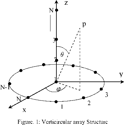
Both the subarrays have same inter-element spacing d between the elements in each subarray, which is assumed to be half of the wavelength. The ULA is used to estimate the elevation parameters (angle and angular velocity) which used as input to determine the azimuth parameters by the UCA. Therefore, the 2D-DOA is performed sequentially which will reduce the required computations compared with utilizing only the UCA.
Assume the signal model for target tracking is:
r (t) = A (t) s (t) + e (t)
Where, A(t) is N x M time-varying direction matrix has N x1 steering vector, s(t) isthe received signal vector of the source waveforms with a size of M x 1 , and e(t) is the N x 1 noise vector which is Gaussian with zero mean and variance <72 .
The steering vector that used with the first subarray (ULA) is:
a^_
(
9
)
=
[
1 e
j
n
sin
—
)
e
i2
^
sin<
^
)
e
i
Where the unknown elevation DOAs parameters are

Therefore,
A ula ( t ) = [ a ( 9 i ( t )) a ( — 2 ( t ))................. а — м ( t ))] (3)
The source motion within the observation interval using Taylor series is,
9 ( t + kT ) = 9 ( t ) + —\ t )( kT ) +— ( kT )2 + — ( kT )- +
= C oe + C 1e kT + C 2e ( kT ) 2 + C -e ( kT )- + (4)
Here, T is the sampling interval.
Assuming that the observation window is sufficiently short and, therefore, the third and later terms in (4) are negligible, so
— ( t + kT ) = C oe + C 1e kT (5)
with
C o e = 9 ( t ), C 1e = 9 (1)( t ) (6)
being the instantaneous source elevation DOA angle and angular velocity, respectively. So, the problem is to estimate the veCtor c e = ( c o e , C 1 e ) T from the nonstationary array observation vector r ( t ) .
On the other hand, the steering vector that used with the second subarray (UCA) is:
a UCA ( 9 , ф ) =
j—sin — ) oos( 0 -2 П N) j—sin( — ) oos( 0 -4 П N)
1 e 2 e 2
N T j — sin( 9 ) Cos( 0 -2 n )
....e '
Where the unknown azimuth DOAs parameters are { Ф ( t £ .
Therefore,
A UCA ( t ) = [ a ( 9 1 ( t ), Ф 1 (t )) a ( — 2 ( t ), ^ 2 ( t )).... a ( 9 M ( t ), ф м ( t ))] (8)
The source motion with the UCA within the observation interval using Taylor series is,
(2) (3)
9 ( t + kT ) = 9 ( t ) + 9 (1) ( t )( kT ) + —^ t ) ( kT ) 2 + — ^' ( kT ) 3 + ..
= C oe + C ie kT + C 2e ( kT ) 2 + C -e ( kT ) - +
ф ( t + kT ) = ф ( t ) + ф (1) ( t )( kT ) + Ф ^t ’ ( kT ) 2 + ^ -^ t ) ( kT ) 3 + ..
= C oa + C ia kT + C 2a ( kT ) 2 + C -a ( kT ) - + (9)
With the assumption that the third and later terms in (9) are negligible when using ULA, so we have
— ( t + kT ) = C o e + C i kT , ф ( t + kT ) = C o a + CakT (10)
With
C 0 a = Ф (t ), C 1a = ф (1)( t ) (11)
being the instantaneous source DOA azimuth angle and angular velocity, respectively. So, the problem is to estimate the veCtor c a = ( c o a , c 1 a ) T from the nonstationary array observation vector r ( t ) .
Then, the LPA beamformer function is applied to estimate both the elevation and azimuth parameters.
2B III. LPA 2D-DOA Estimation Using Verticircular Array
Localization and tracking multiple narrow band moving sources is one of the fundamental problems in radar, communication, sonar, seismology and in other areas. The subspace methods such as MUSIC or ESPRIT, for direction of arrival (DOA) estimation, are based on the Eigen structure of the estimated covariance matrix of the data received by antenna array. As the number of the array snapshots increases, the accuracy of the estimated covariance matrix increases and consequently increases the accuracy of the estimated DOA. However, these methods are still too complicated to admit real-time implementations and they are unsuitable for non-stationary environments. In many applications, such as tracking of a moving source of electromagnetic radiation it is required to estimate the DOA for every new snapshot. The conventional beamforming and high-resolution subspace techniques are mainly developed for unmoving sources. It assumes that only quite short series of observations are allowed to be used in these techniques for beamforming and estimation in nonstationary environment. The conventional methods have a deteriorate performance in the presence of moving sources. The sensitivity of these techniques can be quite high even with respect to small movements. In recent years a significant progress was achieved for the development and application of different source movement models for DOA estimation. Usually these models are assumed to be parametric or locally parametric. These techniques are mainly based on the maximum likelihood (ML) algorithm. Alternative eigenvalue decomposition techniques can be modified for subspace moving source tracking however does not allow incorporating source movement models [26]. On the contrary, the LPA beamformer is a powerful nonparametric technique, which provides estimate for moving sources parameters in a pointwise manner based on a mean square polynomial fitting in a sliding window. A recently proposed nonparametric local polynomial approximation (LPA) beamforming is originated as an adjustment of the conventional beamformer to nonstationary environments with moving sources. It is shown that it is able to yield a very useful visualization of the DOA of rapidly moving sources as well as an improved source resolution. For instance, the LPA beamformer is able to resolve sources with equal DOAs provided that the movement velocities are sufficiently different.
On the other hand, using the verticircular array in the LPA beamformer for 2D-DOA estimation for nonstationary sources will improve the estimation performance in terms of simplicity and reduced computational complexity. Estimates of directions ofarrival (DOA) of the sources and their angular velocitiesare defined by determining the maximum of the LPA function. A tracking ability of the estimates is assured by using the deterministic nonparametric model of a source movement.
The proposed LPA beamformer has a power function. Maximum peaks of this power function are used for source separation and estimation of DOAs and their first derivatives to determine the source’s angular velocities. Exploiting the angular velocity of the source is used to distinguish between many nonstationary sources that may have the same position. A difference in direction and/or speed is required in order to resolve the sources. While a source movement is a nuisance for the traditional methods the LPA beamformers are able to use the movement in order to improve the resolution of tight sources.
For a single source assumption, the LPA beamformer function is found to be [25]:
P ( t , c ) = 1 a E ® h ( kT ) a H ( c , kT >( t + W ) 2 (12)
N E ® h ( kT ) k 1 1
k where . stands for the absolute value, T is the sampling interval and k = 0,1,..., NN -1, where NN is the number of snapshots. N is the number of sensors. This is a linear function with respect to the second order moments of the signal r(t) .
The summation interval in (12) is determined by the window function ® h ( kT ) . The dependence of the steering vector a is expressed via the vector c and the time kT . The window function is given by,
T kT
® h ( kT ) = (-) ® (—) (13)
hh
Where, h is the window width.
To estimate the elevation parameters, we substitute in
-
(12) by c = c e .
Then, after estimating c e substitute by c = ( c e , c a ) in the LPA function and use it to estimate the azimuth direction parameters in the vector c a .
The response to multiple sources represents a direct superposition of particular responses to each source. Therefore, the LPA beamformer can be applied to the scenarios with multiple well-separated sources as well.
As a summary for the 2D-DOA estimation proposed algorithm, the steps can be formulated as:
-
1- Determine the received time-varying sources vectors incident on the array (1),
-
2- Approximate the time-varying function using part of the truncated Taylor series (in terms of the elevation parameters) to acquire the elevation source motion model using the ULA (first subarray) (5),
-
3- Use the weighted least squares approach to formulate the LPA beamformer as in (12) to estimate the elevation parameters (angle and angular velocity) of the sources.
-
4- Use the estimated elevation parameters (obtained from the previous steps using the ULA) to substitute in the steering vector for the UCA.
-
5- Repeat the steps 2 and 3, considering the estimated elevation parameters are known from the previous steps, to estimate the azimuth parameters.
-
IV. Simulation Results
In this section, many simulations are performed to testify the performance of the proposed method.
-
A. DOA Estimation for Different sources cases:
The 2D-LPA beamformer using verticircular array of 10 elements sensors spaced half-wavelength apart in each of the ULA and the UCA, and uncorrelated moving sources with SNR =15dB is exhibited in this section. A rectangular window with N = 50 snapshots is considered in the following cases.
Case 1:
Consider a single source located at the direction: £ 1 ( k ) = 80 ° - 6 ° k , and ^ 1 ( k ) = 300 ° + 5 ° k . The LPAbeamformer can distinguish and localize the correct elevation and azimuth source locations as illustrated in Fig. 2(a,b). The single high peak appeared in the figure indicates the exact source location. It is clear that the proposed array can cover 90 ° in the elevation direction and 360 ° in the azimuth direction.
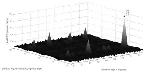
Figure.2: a. The LPA beamformer for the source elevation
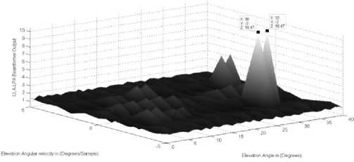
Figure.3: a. The LPA beamformer for the two sources elevation
parameters (80 ° , - 6 ° / sample )
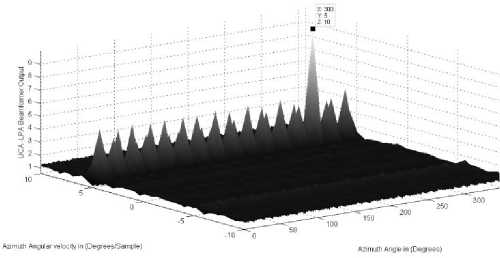
Figure.2: b. The LPA beamformer for the source azimuth parameters (300° ,5° / sample)
parameters( 30 ° , - 2 ° / sample ) and (32 ° , - 2 ° / sample )
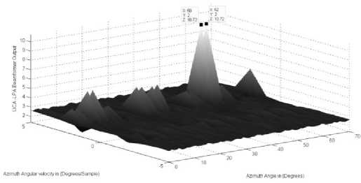
Figure.3: b. The LPA beamformer for the two sources azimuth
Cases 2-3:
These cases show that the LPA beamformer can resolve two sources if they have same angular velocities or angles, respectively.
The elevation locations for the two sources in case 2 are 9 1 ( k ) = 30 ° - 2 ° k , 9 2( k ) = 32 ° - 2 ° k . While, the azimuth locations are ф 1 ( k ) = 50 ° + 2 ° k , ф 2 ( k ) = 52 ° + 2 ° k . Where, in each direction the two sources have the same angular velocities. As clear from Fig. 3 (a,b) the correct location for both sources is detected as indicated by the high peaks in the ULA-LPA beamformer output.
Furthermore, the sources location in case 3 is correctly detected as in Fig. 4(a,b). The elevation parameters for the two sources in this case are 9 1 (k ) = 30 ° - 2 ° k , 9 2 (k ) = 30 ° + 0 ° k . While, the azimuth parameters for the two sources are Ф 1 (k ) = 50 ° + 2 ° k , ф 2( k ) = 50 ° + 0 ° k . It is clear that, in each direction the two sources have the same angles. As clear from Fig. 4 the correct locations for both sources are distinguished and the sources locations are localized using their different angular velocities in both directions. It is clear from the figures that the high peaks of the LPA beamformer exist at the correct sources locations.
parameters are (50 ° ,2 ° / sample )and (52 ° ,2 ° / sample )
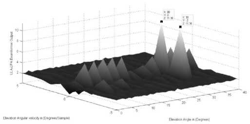
Figure.4: a. The LPA beamformer for the two sources elevation parameters (30 ° , - 2 ° / sample ) and (30 ° ,0 ° / sample )
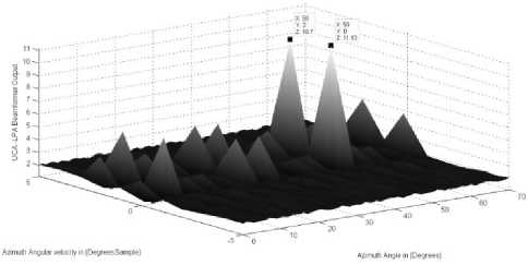
Figure.4: b. The LPA beamformer for the two sources azimuth parameters (50° ,0° / sample) and (50° ,2° / sample)
Case 4:
Consider two sources that have the same angles and angular velocities in the azimuth directions which are (100° ,3° / sample) and the same angle 20° in the elevation direction for both sources and their angular velocities in the elevation direction are different and they are respectively as [(-1°,1°)/sample] . Fig. 5 shows that the LPA beamformer high peaks can distinguish between the two sources through their different elevation angular velocities; a phenomenon that is completely abolished in the conventional beamformers where they cannot resolve this case, where the conventional beamformer deals with stationary sources and there is no angular velocity detection. Consequently, the source angular velocity is exploited to improve the source localization in nonstationary situations and to resolve sources that have the same angle. At the same time, the conventional beamformer is neither able to exploit the source motion nor to resolve closely spaced sources.
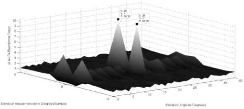
Figure.5: a. The LPA beamformer for the two sources elevation parameters (20 ° ,-1° / sample) and (20 ° ,1° / sample)
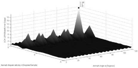
Figure.5: b. The LPA beamformer for the two sources which have the same azimuth parameters (100° ,3° / sample)
Case 5:
Similar to case 4, the two sources have the same values in both directions’ parameters except one parameter. In this case they are differing in the azimuth angular velocities. As illustrated in Fig.6 the LPA beamformer can resolve and indicate the correct sources locations where they have the same elevation parameters at (30 ° ,1 ° / sample ) and 60 ° azimuth angle for both sources. The two sources different azimuth angular velocities are located at [( - 1 ° ,1 ° )/ sample ], respectively which used to resolve the two sources.
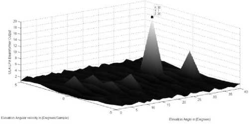
Figure.6: a. The LPA beamformer for the two sources which have the same elevation parameters (30° ,1° / sample)
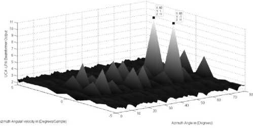
Figure.6: b. The LPA beamformer for the two sources azimuth parameters (60 ° , - 1 ° / sample ) and (60 ° ,1 ° / sample )
-
B. B. Execution Processing CPU Time
To clarify the reduction of calculation burden which is the main purpose of this work; the CPUTIME function in Matlab is used. This function returns the CPU time in seconds that has been used in the algorithm calculations. Where HP platform is used, which has a modest CPU (2.53 GHZ Intel Core 2 Duo) and a moderate memory space (2.90 GB RAM) for data processing.
The elapsed CPU time is computed and compared (for 40 snapshots and SNR 10dB) using the 2D- LPA DOA estimation algorithm for both the proposed method using verticircular array geometry and the rectangular planar array geometry in [25]. The comparison is indicated in Table 1, where it is clear that the proposed method has the advantage of less computation time which leads to less required cost for 2D-DOA estimation.
This result is agreed with the sequence of the verticircular array geometry for 2D- DOA estimation which is mentioned in section III.
The running times are measured for the entire program. The results are presented in Table 1. The column Ratio is defined as
Ratio =
Time for LPA using verticircular array (Proposed method) Time for LPA using rectangular planar array
From Table1, it is clear that using verticircular array running time is about 41% of the complexity associated to using rectangular planar array in 2 sources case. While it is about 43% for 3 sources case. This relationship
indicates the reduction in computational complexity due to the proposed method.
TABLE1. The elapsed CPU computation time for the LPA beamformer with different array geometries.
|
Array geometry UsingLPA No. of Signals |
Rectangular planar array |
Verticircular array (proposed geometry) |
Ratio |
|
Two Signals |
24.2188s |
10.0469s |
41.4839% |
|
Three Signals |
32.0317s |
14.0241s |
43.7882% |
-
V. CONCLUSION
The novel array geometry with nonparametric approach based on the LPA beamformer of time-varying DOA for angle and angular velocity estimations is proposed in this paper. This Verticircular array used to reduce the computation calculation of the angle and the angular estimation with small window size which improves the LPA beamformer performance. The array consists of vertical ULA which is used firstly to determine the elevation DOA parameters which then used to determine the azimuth DOA parameters by a UCA in the horizontal plane. The azimuth DOAs are determined separately which reduce the required search time.
Also, the values of the LPA function at the correct sources location is high and can be easily determined.
The simulations show that this nonparametric technique can resolve closely spaced sources in different scenarios taking into considerations that they are sufficiently different at least in one parameter. Using this verticircular array makes the LPA beamformer relevant for accurate and practical 2D-DOA estimation for nonstationary sources. Also, simulation results show that the performance of the proposed method provides less complexity than that obtained when using rectangular planar array, which is the gain of using verticircular array geometry.
References LPA 2D-DOA Estimation for Fast Nonstationary Sources Using New Array Geometry Configuration
- Zhang, X., X. Gao, and Z. Wang, “Blind paralind multiuser detection for smart antenna CDMA system over multipath fading channel,” Progress In Electromagnetics Research, Vol. 89, 23-38, 2009.
- Byrne, D., M. O'Halloran, M. Glavin, and E. Jones, “Data independent radar beamforming algorithms for breast cancer detection,” Progress In Electromagnetics Research, Vol. 107, 331-348, 2010.
- Nishiura, T. and S. Nakamura, “Talker localization based on the combination of DOA estimation and statistical sound source identification with microphone array,” IEEE Workshop Statistical Signal Processing, 597-600, Oct. 2003.
- X Zhang, Theory and application of array signal processing, National Defense Industry Press, Beijing, 2010.
- X Zhang, D Xu, “Improved coherent DOA estimation algorithm for uniform linear arrays,” Int J Electron, 96(2), 213–222, (2009).
- H Chen, B Huang, Y Wang, “Direction-of-arrival estimation based on direct data domain (D3) method,” J SystEng Electron, 20(3), 512–518, 2009.
- X Zhang, X Gao, D Xu, “Multi-invariance ESPRIT-based blind DOA estimation for MC-CDMA with an antenna array,” IEEE Trans Veh Technol., 58(8), 4686–4690, 2009.
- Y Hua, “A pencil-MUSIC algorithm for finding two-dimensional angles and polarizations using crossed dipoles,” IEEE Trans Antennas Propag., 41(3), 370–376, 1993.
- JE Fern’andez del R’io, MF C’atedra-P’erez, “The matrix pencil method for two-dimensional direction of arrival estimation employing an L-shaped array,” IEEE Trans Antennas Propag., 45(11), 1693–1694, 1997.
- P Krekel, E Deprettre, “A two dimensional version of matrix pencil method to solve the DOA problem,” in Proceedings of European Conference on Circuit Theory and Design, 435–439, 1989.
- Chiao-En Chen, Theory and applications of parametric estimation methods for sensor array signal processing, Dissertation, California University, 2008.
- Md.Bakhar, Vani.R.M and P.V.Hunagund “Comparative studies of direction of arrival algorithms for smart antenna systems,” World Journal of Science and Technology, 1(8), 20-25, 2011.
- Pei-Jung Chung, Johann F Böhme and Alfred O Hero,” Tracking of Multiple Moving Sources Using Recursive EM Algorithm,” EURASIP Journal on Advances in Signal Processing, 2005.
- U Baysal, RL Moses, “On the geometry of isotropic arrays,” IEEE Trans Signal Processing, 51(6), 1469–1478, 2003.
- Sotiriou, A. I., P. K. Varlamos, P. T. Trakadas, and C. N. Capsalis, “Performance of a six-beam switched parasitic planar array under one path Rayleigh fading environment, ” Progress In Electromagnetics Research, Vol. 62, 89-106, 2006.
- Wang, G. M., J. M. Xin, N. N. Zheng, and A. Sano, “Two-dimensional direction estimation of coherent signals with two parallel uniform linear arrays,” IEEE Statistical Signal Processing Workshop (SSP), 2011.
- YHua, TK Sarkar, DD Weiner, “An L-Shaped array for estimating 2-D directions of wave arrival,” IEEE Trans Antenna Prop., 39(2), 143–146, 1991.
- N Tayem, HM Kwon, “L-Shape 2-dimensional arrival angle estimation with propagator method,” IEEE Trans Antenna Prop., 53(5), 1622–1630, 2005.
- SW Ellingson, “Design and evaluation of a novel antenna array for azimuth angle-of-arrival measurement,” IEEE Trans Antenna Prop., 49(6), 971–979, 2001.
- WG Diab, H. Elkamchouchi, “A deterministic approach for 2D-DOA estimation based on a V-shaped array and a virtual array concept,” IEEE 19th International Symposium on Personal, Indoor and Mobile Radio Communications, 1–5, 2008.
- Yufeng Zhang, Zhongfu Ye, Chao Liu, “An efficient DOA estimation method in multipath environment,” Signal Processing, 90, 707-713, 2010.
- Ping TAN,PianWANG,YeLUO,YufengZHANG,Hong MA,” Study of 2D DOA estimation for uniformcircular array in wireless location system,” IJCNIS, Vol.2, No.2, 2010.
- CP Mathews, MD Zoltowski, “ Eigen structure techniques for 2-D angle estimation with uniform circular arrays,” IEEE Trans Signal Processing 42(9), 2395-2407, 1994.
- M Pesavento, JF Böhme, “Direction of arrival estimation in uniform circular arrays composed of directional elements,” Proc Sensor Array and Multichannel Signal Processing Workshop, 503–507, 2002.
- H. Elkamchouchi, M. E. Nasr and A. S. Ashour, “Planar array for signal tracking using sliding window approach,” 21th National Radio Science conference (NRSC), B10, March 2004.
- Vladimir Katkovnik, Adaptive Robust Array Signal Processing for Moving Sources and Impulse Noise Environment, TICSP Series #11, December 2000.
