Mathematical modelling of thermo-mechanical stresses arising in rectangular supports of thermoelectric modules

Free access
Traditionally available unsegmented thermoelectric modules are simple to operate but their applications are limited. Whereas, segmented thermoelectric modules have got significant amount of advantage over unsegmented thermoelectric modules, materially and performance vise, but structural reliability is still unresolved challenge. Thermoelectrical module encounters high stresses due to increase in operating temperature and difference in coefficient of thermal expansion. Consequently, these stresses create deformation and cracks in thermoelectric legs, especially at higher temperature. In this paper a comprehensive analytical model for Thermoelectric modules is discussed. The model can predict thermally induced and shearing stresses in Thermoelectric module. The contemplation of geometrical shape for thermoelectrical module is limited to rectangular and beam-like design, for unsegmented and segmented modules. The analytical model was compiled in MATLAB and Python and results are discussed in detail.
Thermoelectric, thermomechanical stresses, stress-strain relationship, shear stress
Short address: https://sciup.org/148321622
IDR: 148321622 | UDC: 621.3+51.74 | DOI: 10.25586/RNU.V9187.21.01.P.023
Математическое моделирование термомеханических напряжений для прямоугольных сегментированных и несегментированных ног
Традиционные имеющиеся несегментированные термоэлектрические модули просты в эксплуатации, но их применение ограничено из-за низкой эффективности преобразования. Сегментированные термоэлектрические модули имеют значительное преимущество по материалу и по рабочим характеристикам по сравнению с несегментированными термоэлектрическими модулями, но проблема их конструктивной надежности при средней и высокой температурах (до 1000 °C и более) до сих пор не решена. Сегментированные модули сталкиваются с высокими напряжениями из-за повышения рабочей температуры. Следовательно, эти напряжения создают деформацию (изгиб, прогиб) и трещины на термоэлектрических опорах. В данной работе рассматривается комплексная аналитическая модель для термоэлектрических модулей. Полученная модель позволяет предсказать термически индуцированные напряжения и напряжения сдвига на кромке компонента. Созерцание геометрической формы для термоэлектрических модулей ограничено прямоугольной и балочной конструкцией, для несегментированных и сегментированных модулей. Аналитическая модель была составлена в MATLAB и Python, результаты подробно обсуждаются.
Text of the scientific article Mathematical modelling of thermo-mechanical stresses arising in rectangular supports of thermoelectric modules
Due to the absence of moving parts, and, as a result, the reliability that allows such systems to operate in unattended mode for a long period of time, today there is practically no alternative to such generators in space exploration. When TE modules are subjected to thermal cycling, thermally induced stresses go beyond yield and tensile strength, which ultimately leads to failure of module. Several experimental studies have focused on evaluating and minimizing the stresses during the operation in TE applications. Main findings of the literatures concluded that thermomechanical stresses are influenced by i) type of materials [30], ii) leg’s geometry [17] and iii) boundary conditions [31].
To predict sustainability of the TE leg, thermally induced stresses are viewed as major bottlenecks for robustness, especially for high temperature thermoelectric modules [24]. Another side of studies also publicized that high stress levels in TE legs arise, with respect to high temperature gradients, due to mismatch of thermal expansion coefficients at the interface [23]. Particular solutions are proposed that by varying the leg geometry of unsegmented leg we can suppress stress level but within certain length to thickness ratio [25]. But contrary to unsegmented leg by increasing the length to thickness ratio(adding more layers) in segmented leg case, although we can maximize the output but, the module undergoes deformation due high stress level [19]. Especially the introduction of anti-diffusion layers, in segmented case, can aggravate stress level, whereas alleviate the performance [7]. Segmented TE Legs can generate up to 17% [28] electrical energy and the reliability of the segmented TE leg is not steady [9]. Whereas, unsegmented TE leg can’t provide output, as we can get nearly 7%, as much as segmented leg but can sustain its basic structure more than 40 years [6].
Mathematical Modelling of Thermo-Mechanical Stresses Arising ...
Analytically Timoshenko developed a fundamental relationship between temperature and stress [14], which was extended by Suhir by defining the effect of length and thickness on stress level in TE leg. Suhir’s [26] mathematical model, on TE legs, gives insight to understand effect of shear stress between the layers and at the boundaries. Malzbender’s [13] work demonstrates the effect of stiffness, thickness and thermal expansion on stress level. Z.-H. Jin [10] continued Malzbender’s model and predicted that failure can occur in multilayer leg, if length to thickness ratio increases. G. Nikolova [15] developed a comprehensive mathematical model to study thermal and mechanical behavior of bonded layers. She has demonstrated that debonding (failure) of layers happen when module reaches at its critical shearing stress. Nao take [16] develop a very comprehensive mathematical model for rectangular plate and studied their thermal-mechanical behavior at different temperature gradient.
In this paper we have considered Naotake’s plate theory and applied it to provide an alternative prospect, especially in field of thermoelectric generators. Particularly, the impact of shearing stress, shearing strain, thermally induced bending stress and shear forces are discussed. The presented analytical model is comprehensive and easy to predict thermo-mechanical stresses in TE leg to calculate reliability of the TE module.
Analytical Model
The basic TE leg and its components are demonstrated in Figure 1. The analytical model is derived using a specific geometry (rectangular) for TE leg, as shown in Figure 2, and each layer is connected perpendicularly to one another. The basic distinction between segmented and unsegmented leg is that former’s thermoelement is made of single material whereas latter has two (or more than two).
For unsegmented leg length to thickness ratio, according to the following articles [4, 5], has been considered between 0.5–0.9% due to effectiveness and low level of stress. The coordinate plane for TE leg is shown in Figure 2 and the boundary conditions, discussed below in details, make physically possible for leg to expand on in plane direction while develop stress out of plane direction.
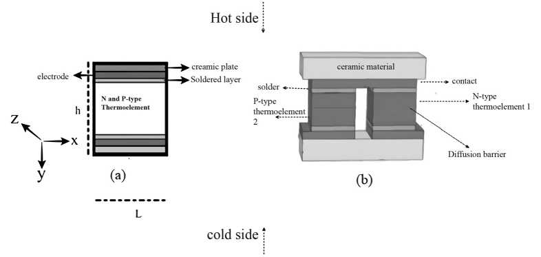
Figure 1. (a) Unsegmented and (b) segmented TE legs
Моделирование технических устройств
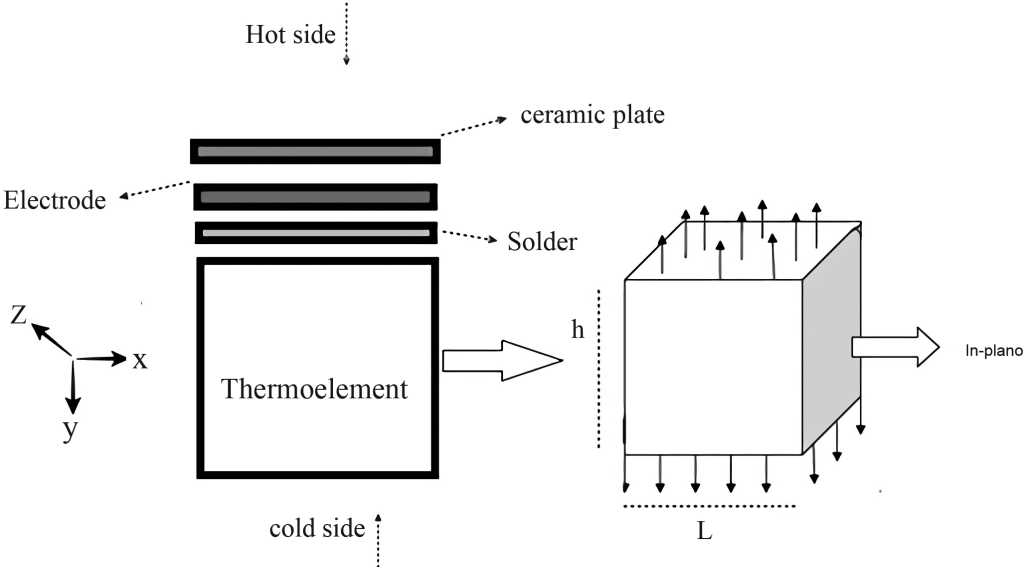
Figure 2. Basic Structure of TE leg comprised from different components
Let u, v, and w be displacement components in the x, y, and z direction at the neutral plane (z = 0). The two-dimensional stress-strain relationship [3], in-plane direction, for an isotropic
|
component |
o x = — ( ^ x - v ^ y ) + a A T E Oy = 1 ( O y - v ox ) + a A T (1) E
Oxy = E O xy
ff y = 1 _ v 2 [ e y + v 6 x ( 1 + v ) а Д T ] (2) E a =---- 6 xy xy 1 + v |
Here, E is young modulus, σ is stress, α is coefficient of thermal expansion and v is Poisson ratio and ΔT is change in temperature [27]. In order elaborate he thermoelastic behavior of the leg, we define the resultant forces and resultant moment per unit thickness for each component with respect to x, y, and z- axis, as product of stress σ and strain ht/2 h/2
F = о dx, F = о dy, F = о dz.
x -h/2 x , y -h/2 y y, xy -h/2 xy hi/2 h/2
Mx = J-h/2°xXdx, My = 1h/2°уУd, Mxy = 1-h/2°xyZdZ■
Now substituting the value of stress in equation (3) and (4) and integrating accordingly, we get solution for resultant force and moment equations
Mathematical Modelling of Thermo-Mechanical Stresses Arising ...
Eh
F x 2
1 — v
д и д v --+ v— д x д y
FT
1 — v
Eh
F y 2
1 — v
д v д u
--+ v— д y д x
FT
1 — v
F xy
Eh
д и д v
2 ( 1 + v дд y д x ,
m д w д w .
M„ =— D —z-+—T-- M.
д x 2 д y 2 J
x
1 — v
T
д 2 w д w
M„ =— D —- + —r-- M.
"•2 д x 2 '
y
1 — v
T
M = (1 — v)D xy дx дy
Here FT , MT , D, are thermally induced force, thermal bending moment and flexure rigidity and defined as [11, 16]. Now by substituting equation (5) and (6) into equation (2), we’ll get stress each component of rectangular TE leg
_ 1 12 z„ 1 (112 о — N + , Mx + N + i M- xx3xT 3
h h 1 — v V h h
_ 1 12 z^ 1 (112
°y hNy+ h3 y + 1—v V hNT + h3:
112z xy xy 3 xy hh
— aE A T
— aE A T
This Equations satisfy the Kirchhoff hypothesis [2] for in-plane stress. We now consider the equilibrium state for the plane stresses for x and y . When body forces are absent, integrating equilibrium equations, defined in [16], we get thermal stress function φ [20]. The compatibility equation and stress function φ for by plane strain gives us fundamental equation of force
∇2∇2 φ =-∇2 FT
2 d2 d2 _ _ (* /2
Here V = + , FT = aE A TdT .
d x 2 d y 2 T — -h / 2
The equation (8) is a basic equation to understand thermoelastic behavior of TE leg. Through this equation we can find thermally induced force for each part in plane direction.
Equation of Displacement
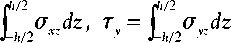
When specific temperature field is given, displacement, stress and strain are sought. Consequently, if displacement equation is given, stress, strain and external forces are sought [18]. To drive basic equation of displacement let’s say τx and τy are the shearing forces per unit length for x and y direction and can be defined as function of stress
Моделирование технических устройств
Introducing equilibrium equations of moments for “x” and “y” components
5Mx 6M
—x +—y - т = 0
dx dy
dMy 6Mxy - тdy dx y
=0
By comparing equation (6) and (9) we know that we understand that Myx = – Mxy . Since shear forces are concentrated on edges, causing thermally induced bending moment, we get the fundamental equation of displacement (in the absence of external load)
∇2w=
-
1 M
D (1 - v )
h /2
Here M = α E ∆ Tzdz
T - h /2
Equation (10) is used to calculate the deformation caused by thermally induced stress and bending moment. By specifying boundary condition, we can develop an analytical equation for deformation for out of plane direction.
Boundary Condition – Vertically Restricted Ends
The boundary conditions, demonstrated in Figure 3 , are taken into consideration according the use of interdiffusion layer. The interdiffusion layer, especially in case of segmented TE leg, restricts the thermal expansion each material. Hence leading to bending moment on horizontal axes and thermally induced stress on vertical boundaries.
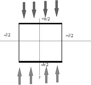
Figure 3. Boundary conditions – Vertically restricted and horizontally free
These conditions are defined according to axis, which are l
At x = ±—
6w w w=°' a. x-
D (1 - v )
MT
Mathematical Modelling of Thermo-Mechanical Stresses Arising ...
2dw w = 0, --= 0 dy
With respect to Newmann condition [8] and Boas Theorem [1], we know that the displacement equation at arbitrary x and y points, is double cosine series at particular temperature, which is
w
(x, y, T )=
to to
Z Z m =135 n=135
1 ) a mn
(1 - v ) D J am 2 + вп 2
mn
Here α m
mπ mπ
= β = and are defined by boundary conditions. Regarding to our lnh boundary conditions, the elastic problem of a restricted edge (y = ± h/2) causes a generation
of force (φy) within a volume on y-axis direction. The force is distributed symmetrically and can be defined as to
Ф = 7 E sin ay ymm m =135
Here, Em is elastic constant and depends on boundary conditions. For the boundary condition ( x = ± l /2), the displacement equation is
V2V2 w 2 = 0
And according to fourth-order partial differential equation, the above equation has following solution to
x mmmm
l
For x =±—
m = 135
A cos hYm + B Y sin hYm = 0
h
And for y = +—
E m
D
mπ h h
Here Y m = and product of length to thickness ratio. On y = + — , equation of equilibrium gives us the equation for elastic constant, that is
E
m
2 ( am cosh2Ym ) j^ атпвп (-1) 2
1 - v l Y m + sin h Y m + cos h Y m ) n ^S a ^m + в 2
^us, for the boundary conditions x =± — , the resultant moment and shearing forces, due to displacement can be calculated through equation (6)
Моделирование технических устройств
-
1 E
M x = - E Г" { ( 1 - v ) а т У sin h a m y -E 2 v + ( 1 - v ) Y m tan Y m ]cos h a „ y }cOS a mx
-
2 m ^COS hYm
-
1 « E (14)
М У =7 E --- Г" { ( 1 - v ^У sin h a m y Ч2-( 1 - v ^ Y m tan Y m ]coS h^ }cOS a x
-
2 m =^COS hY m
to
T x =- Z
m =135
to
E
m cos h α m y sin α mx cos h γ m
T y = L
m = 1,3,5
E
m
cos h γ m
sin h α m y cos α mx
h
For the restricted boundary (condition ( y = ±— ), the deformation (displacement) and shearing forces can be concluded by using superposition theorem.
w y
X
— 1 E 2 D m =135
" (1 — v ) D
E m α 2 cos h γ mm
X X z z m =1 35 n =135
a mn
m
2 mn
n
mmmm mm
^ E a m m m_1,3,5 cos hYm
coshαmysinαmx
^ E a
__ m m m_Т3,5 cosh Ym
sinh αm ycos αmx
Through equation (16–17) we can find thermally induced stress and shear stress on edge of each component. The concentrated shear stress ( τx and τy ) are tensile nature stresses and cause deformation, interlayer diffusion, dislocation, and cracks at interference.
Segmented TE Leg Equation
This force Fd is a resultant force produced due to mismatch of coefficient of thermal expansion (α ) between the layers.
|
layern |
h„ |
|
layeri |
h i |
|
layer j |
|
|
layer 1 |
Figure 4. Multi-layer TE leg (segmented case)
Mathematical Modelling of Thermo-Mechanical Stresses Arising ...
Fd = F + Fα
-
j. E ( T )
Fd = Z j-----2 aj(y,T)dT(y)УдУ
=1 h-i 1 - v
Consequently, the resultant moment is
Md = M + Mα
Here,
Md = 1L П^(y,T) a(y,T)dT(y)ydy
1-v j=1 hj-1 T0
Now introducing separation of variables method and constructing relationship between forces, moments, and shear strain at the interference between two adjoining layers are
F d
M d
AB
BD
ε x , 0 k
Here A, B, D and K represents extensional coefficient, flexural-Extensional coupling coefficient, flexural stiffness coefficient and interfacial shear compliance (curvature of the leg) respectively and can be define as n^Ej.y У, T)
A = Z— 2 ( y - y - i ) j = 1 1 - vj
1 V E j' ( У ’ T)( 2 2
B = 21 -v2 (yj -У-')
Now in order to find the strain, the inverse matrix of equation (20) is x ,0 k
And the solution for this equation
ε x,0
k =
A
B
B
D
—
1 Г F d
M d
D( Fd) + B( Md)
B2 - AD B( Fd) - A( Md)
B2 - AD
At position y that is perpendicular to the interference between layers the interface strain and stress is define as
T i j
6x,y,j = 6x,0 + yk- Jaj ( T-У) dT(У)
E
c . =----- x- y- j , 2
1 - v
T 0 j
T 1, j
ex,0+ yk - Jaj(T-y)dT(y)
T o. ,
Моделирование технических устройств
Results and Discussion
The investigation presented in this paper is continuity of our previous papers [21, 22] to understand development of thermal stress in TE leg. Figure 5 (a) shows the calculated value of segmented and unsegmented modules using equation of heat flux and stress. Whereas Figure 5 (b) demonstrates comparison of maximum stress between different TE components. Figure 5 demonstrates the difference in thermal expansion coefficient (α), Elastic modulus ( E ) and Poisson ratio of each material with respect to temperature distribution.
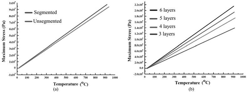
Figure 5. Comparison of for (a) maximum stress, (b) maximum stress in each component
Whereas, Figure 6 indicates that there is an incline in maximum stress when the thickness of the leg (or component) is increased. The investigation on shear and normal stresses, shown in Figure 6 and Figure 7, indicates that the increase in thickness can leads to thermally induced interfacial stresses which eventually cause deformation and cracks.
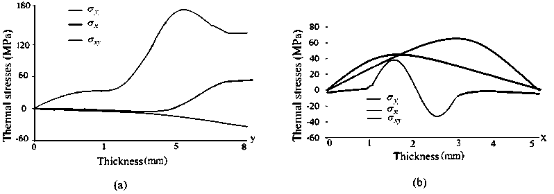
Figure 6. (a) Shear stresses leading to tensile stresses at edges whereas (b) resultant stresses leading to compressive stresses in Y direction
From the Figure 7 (a) we can observe that when boundaries are restricted vertically a proportional relationship between temperature and deformation developed. This relationship states that the edge of the leg causes tensile nature stresses in both x and y direction, whereas resultant force, shown in Figure 6, develops compressive stresses in y-direction. From Figure 6 and Figure 7 it can be observed that the tensile stresses are develop within 3.5mm ≤ x ≤ 5mm and compressive stresses within 4mm ≤ y ≤ 8mm.
Mathematical Modelling of Thermo-Mechanical Stresses Arising ...
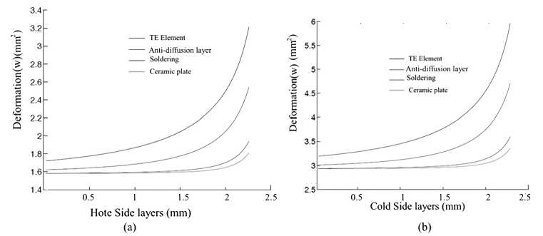
Figure 7. Deformation at (a) hot end and (b) cold end with respect to their thickness
In segmented TE leg, an addition of interdiffusion layers and soldering layers cause higher rate of deformation compared to unsegmented legs [12]. The demonstrated results of Figure 7 are obtained using equation of displacement for hot and cold side of the TE leg. The deformation product of thermal stresses causing plastic deformation in soldering and interdiffusion layers. The thickness of soldering and interdiffusion later was kept between 0.7 mm≤ h ≤ 1.5 mm. Therefore, these layers deform with respect to TE element at melting point temperature above 200C.
(a)
(b)
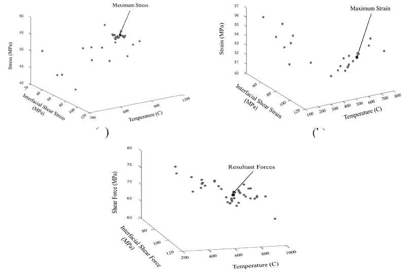
Figure 8. (a) (b) (c). Pareto Front of stress-strain-temperature relationship
34 м оделирование технических устройств
The equation of displacement, thermal bending moment, shearing stress and multi-leg are simulated in python to obtain Pareto Front. Pareto Front profile, shown in Figure 8, evaluates the thermally induced shearing stresses, force and strain in TE leg according to their configuration. Pareto Front of Figure 8 (a) indicates that the maximum stress occur at higher temperature in unsegmented leg. The absence of interdiffusion layer and isotropic material use as thermoelement, at specific length to thickness ratio, deform the only when stress increases the strength of the module. Figure 8 (a) shows that the most of device failing on maximum stress are between 400 C to 700 C. In case of segmented leg, shearing strain increases the average stress of the TE leg, mainly due to difference in coefficient of thermal expansion of different material. Figure 8 (b) shows that deformation in segmented leg occurs mostly on interface between the materials. The obtain simulating results on shearing force, shown in Figure 8 (c), are compared with the reference to Jin [10, 29]. It is evident that the shear forces play more significant role in leg’s buckling failure in segmented case as compare to unsegmented leg. These shear forces, for rectangular design, contribute to maximum normal stress up to 55% at hot end and 21.7% at cold end. Consequently, the effect of bending stresses on the TE leg specifies the change of moment of inertia with varying values of shear forces. Therefore, maximum bending stress develops a directly proportional relation to the moment of inertia. The maximum bending stress leads the shear forces in components vertically (restricted at y-axis), whereas interfacial shear forces are ignorable due to their possibility to diffuse into neighboring materials.
Conclusion
The analytical model is used to analyzed thermo-mechanical behavior of a vertically restricted rectangular TE leg by considering their resultant shear force, thermally induced shearing strain and stress per unit thickness. Through simulating results, it has been demonstrated that high length to thickness ratio rise compressive-tensile nature thermal stresses and cause deformation (failure) after a specific temperature gradient. The analytical model can predict thermomechanical stress in TE leg, specifically for rectangular shape TE leg. Pareto Front results suggest that the segmented TE leg is more vulnerable to thermally induced stress as compare to unsegmented TE leg. The effect of extension-bending coupling, flexural stiffness and Poisson’s ration on thermal stress are significantly included in present model to calculate effect of shearing force. Shearing force cause bending moment (deformation) in unsegmented leg, whereas in segmented leg it causes inter-layer diffusion.
Mathematical Modelling of Thermo-Mechanical Stresses Arising ...
36 м оделирование технических устройств
References Mathematical modelling of thermo-mechanical stresses arising in rectangular supports of thermoelectric modules
- Boas R.P. Integrability of Trigonometric Series // Duke Mathematical Journal. 1951. Vol. 18, no. 10. Pp. 787–793.
- Carrera E., Fazzolari F.A., Cinefra M. (Eds.). Thermal Stress Analysis of Beams, Plates and Shells. Oxford: Academic Press, 2017. Pp. 91–116.
- Epstein J.M. Agent_Zero: Toward Neurocognitive Foundations for Generative Social Science. Princeton: Princeton University Press, 2016. 192 p. DOI: 10.2307/j.ctt5hhp5x.7
- Erturun U., Erermis K., Mossi K. Effect of Various Leg Geometries on Thermo-Mechanical and Power Generation Performance of Thermoelectric Devices // Applied Thermal Engineering. 2014. Vol. 73, no. 1. Pp. 128–141. DOI: 10.1016/j.applthermaleng.2014.07.027
- Erturun U., Erermis K., Mossi K. Influence of Leg Sizing and Spacing on Power Generation and Thermal Stresses of Thermoelectric Devices // Applied Energy. 2015. Vol. 159. Pp. 19–27. DOI: 10.1016/j.apenergy.2015.08.112
- Furlong R.R., Wahlquist E.J. U.S. Space Missions Using Radioisotope Power Systems // Nuclear News. April, 1999. Pp. 26–34.
- He W., Zhang G., Zhang X., Ji J., Li G. Recent Development and Application of Thermoelectric Generator and Cooler // Applied Energy. 2015. Vol. 143. Pp. 1–25. DOI: 10.1016/j.apenergy.2014.12.075
- Henry J., Ramos A.M. (Eds.). Factorization of Boundary Value Problems Using the Invariant Embedding Method. Amsterdam: Elsevier, 2016. 256 p.
- Ike Suchih Chi, Smith K., Chen-Kuo Huang, Firdosy S. et al. Advanced Skutterudite-Based Unicouples for a Proposed Enhanced Multi-Mission Radioisotope Thermoelectric Generator: An Update // Journal of the Electrochemical Society. 2017. DOI: 10.1149/ma2017-02/27/1175
- Jin Z.H. Thermal Stresses in a Multilayered Thin Film Thermoelectric Structure // Microelectronics Reliability. 2014. Vol. 54, no. 6-7. Pp. 1363–1368. DOI: 10.1016/j.microrel.2014.02.028
- Johnson T.F., Pilkey W.D. Accurate Thermal Stresses for Beams: Normal Stress / NASA Technical Reports Server [Digital Resource]. – URL: https://ntrs.nasa.gov/api/citations/20040001054/downloads/20040001054.pdf (Date of Application: 02.12.2020).
- Lee M.Y., Seo J.H., Lee H.S., Garud K.S. Power Generation, Efficiency and Thermal Stress of Thermoelectric Module with Leg Geometry, Material, Segmentation and Two-Stage Arrangement // Symmetry. 2020. Vol. 12, no. 5. DOI: 10.3390/SYM12050786
- Malzbender J. Mechanical and Thermal Stresses in Multilayered Materials // Journal of Applied Physics. 2004. Vol. 95, no. 4. Pp. 1780–1782. DOI: 10.1063/1.1642289
- Morley L.S.D., Filonenko-Borodich M. Theory of Elasticity // The Mathematical Gazette. 1967. Vol. 51, no. 378. Pp. 376–377. DOI: 10.2307/3613011
- Nikolova G., Ivanova J. Interfacial Shear and Peeling Stresses in a Two-Plate Structure Subjected to Monotanically Increasing Thermal Loading // Journal of Theoretical and Applied Mechanics. 2013. Vol. 51, no. 4. Pp. 937–947.
- Noda N., Hetharski R.B., Yoshinobu T. Thermal Stresses. 2nd Ed. Boca Raton: Routledge, 2003. 508 p.
- Pan T., Gong T., Yang W., Wu Y. Numerical Study on the Thermal Stress and its Formation Mechanism of a Thermoelectric Device // Journal of Thermal Science. 2018. Vol. 27, no. 3. Pp. 249–258. DOI: 10.1007/s11630-018-1006-3
- Rees D.W.A. Mechanics of Solids and Structures. 2nd Ed. London: Imperial College Press, 2000. 752 p. DOI: 10.1142/9781860943065_0001
- Tian H., Jiang N., Jia Q., Sun X., Shu G. et al. Comparison of Segmented and Traditional Thermoelectric Generator for Waste Heat Recovery of Diesel Engine // Energy Procedia. 2015. Vol. 75. Pp. 590–596. DOI: 10.1016/j.egypro.2015.07.461
- Sadd M.H. (ed.). Elasticity. Burlington: Academic Press, 2005. Pp. 123–138.
- Sattar S. Measuring Probability of Failure of Thermoelectric Legs through Lognormal and Weibull Distribution // Journal of Physics: Conference Series. 2020. Vol. 1560, no. 1. DOI: 10.1088/1742-6596/1560/1/012025
- Sattar S., Osipkov A. Understanding Reliability of the Thermoelectric Devices for Space Application // Advances in the Astronautical Sciences. 2020. Vol. 170. Pp. 591–605.
- Siju K.C., Kumar M. Reliability Analysis of Time Dependent Stress-Strength Model with Random Cycle Times // Perspectives in Science. 2016. Vol. 8. Pp. 654–657. DOI: 10.1016/j.pisc.2016.06.049
- Suhir E. Stresses in Bi-Metal Thermostats // Journal of Applied Mechanics. 1986. Vol. 5, iss. 3. Pp. 657–660.
- Suhir E., Shakouri A. Assembly Bonded at the Ends: Could Thinner and Longer Legs Result in a Lower Thermal Stress in a Thermoelectric Module Design // Journal of Applied Mechanics. 2012. Vol. 79, no. 6. DOI: 10.1115/1.4006597
- Suhir E., Shakouri A. Predicted Thermal Stress in a Multileg Thermoelectric Module (TEM) Design // Journal of Applied Mechanics. 2013. Vol. 80, no. 2. Pp. 1–12. DOI: 10.1115/1.4007524
- Suter C., Tomeљ P., Weidenkaff A., Steinfeld A. Heat Transfer and Geometrical Analysis of Thermoelectric Converters Driven by Concentrated Solar Radiation // Materials. 2010. Vol. 3, no. 4. Pp. 2735–2752. DOI: 10.3390/ma3042735
- Zakrajsek J.F., Woerner D.F., Fleurial J.-P. NASA Special Session: Next-Generation Radioisotope Thermoelectric Generator (RTG) Discussion / NASA Radioisotope Power Systems [Digital Resource]. – URL: https://rps.nasa.gov/resources/69/next-generation-radioisotope-thermoelectric-generator-presentation/ (Date of Application: 02.12.2020).
- Zhang A.B., Wang B.L., Wang J., Du J.K. et al. Thermodynamics Analysis of Thermoelectric Materials: Influence of Cracking on Efficiency of Thermoelectric Conversion // Applied Thermal Engineering. 2017. Vol. 127. Pp. 1442–1450. DOI: 10.1016/j.applthermaleng.2017.08.154
- Zhou X. et al. Routes for High-Performance Thermoelectric Materials // Materials Today. 2018. Vol. 21, no. 9. Pp. 974–988. DOI: 10.1016/j.mattod.2018.03.039
- Ziabari A., Suhir E., Shakouri A. Minimizing Thermally Induced Interfacial Shearing Stress in a Thermoelectric Module with Low Fractional Area Coverage // Microelectronics Journal. 2014. Vol. 45, no. 5. Pp. 547–553. DOI: 10.1016/j.mejo.2013.12.004
