Металлические конструкции кровли нового терминала аэропорта Пулково

Автор: Дягилев Георгий Сергеевич
Журнал: Строительство уникальных зданий и сооружений @unistroy
Статья в выпуске: 3 (30), 2015 года.
Бесплатный доступ
Первая очередь строительства нового терминала Международного Аэропорта Пулково была введена в эксплуатацию 4 декабря 2013 года. Вторая очередь развития начнется сразу же после перевода всех рейсов из Пулково-2 в реконструируемое здание аэровокзала Пулково-1 в начале 2015 года. Выдающаяся кровля Нового терминала была спроектирована с учетом сложных климатических условий. Кровля терминала задумана секционной, напоминает кроны деревьев и может выдержать колоссальную нагрузку от снега в зимние месяцы. Конструкции кровли выполнены из стали, в то время, как, несущие конструкции терминала возведены из железобетона. Статья рассказывает об архитектурных особенностях, геометрии, конструктивной схеме кровли и ее особенностях. Также проведено сравнение двух независимых расчетов несущей способности.
Терминал аэропорта, аэропорт пулково, кровля терминала, кровельные конструкции, большепролетные фермы
Короткий адрес: https://sciup.org/14322218
IDR: 14322218 | УДК: 692.44/.47
Текст научной статьи Металлические конструкции кровли нового терминала аэропорта Пулково
Roof structure is the main architectural concept of the new passenger terminal at Pulkovo Airport. Design was developed by London architectural bureau Grimshaw & Partners Ltd. To emphasize the St. Petersburg style, architects used elements for which the city is well known, namely bridges, rivers and islands. The roof design is a metaphor, becoming gold by sunlight — causes in memories gilded domes of the city churches and its famous “white” nights [1].
Main assignment for the designers was to analyse and introduce the best type of terminal hall structural scheme and calculate it. English engineers used both European Codes and Russian National Codes to work out and calculate terminal structure [2]. However to adopt construction project drawings and specifications for authority’s examination it was decided to make second calculation. Russian engineers made it few months later and got different structural design.
In this report I will try to research why results were not agreed with each other and what factors had action upon this.
Terminal hall structure
The roof structure is of steel construction and covers the main terminal building and the areas directly in front of the east and west facades. The roof is approximately 270 m by 162 m on plan, equating to an area of 43740 m².
The roof structure is arranged on an 18 m x 45 m orthogonal roof column grid. The principal structural elements are steel planar trusses spanning 48 m diagonally between the roof columns. In addition to these, planar trusses also span 45 m longitudinally between the columns. Orthogonal rafters span over the trusses and cantilever to pick up the edges of the roof lights or form the roof perimeter. This ‘star’ arrangement of trusses creates space for longitudinal roof lights whilst creating a stiff structure, which acts as a grillage to resist vertical loads and a diaphragm to distribute lateral loads between the stability elements [3, 4].
Octagonal reinforced concrete columns provide vertical support. Around the terminal perimeter and across the baggage reclaim void these are very large stability ‘mega columns’ which taper from their base at ground level to their head beneath the roof soffit. The remaining ‘internal columns’ rise from Level 3 to the roof soffit and resist vertical loads only so they are correspondingly smaller, but still tapered.
Internally the roof architecture comprises of 9 discrete bays, each 18 m wide and separated by a series of roof lights. Each bay is approximately 270 m long and split into 6 discrete geometric units each 45 m long, see Fig. 1.
Externally each 18 m x 45 m unit is split into 2 planes that fall (5o) towards a central gutter to allow drainage and avoid excessive rainwater accumulation at any one specific point. The width of the unit varies along its length. The minimum width is 12 m over supports, where the roof lights are at their widest. These increases up to a maximum of 18 m at the unit’s mid-span, where the diagonal trusses cross at the ends of the roof lights.
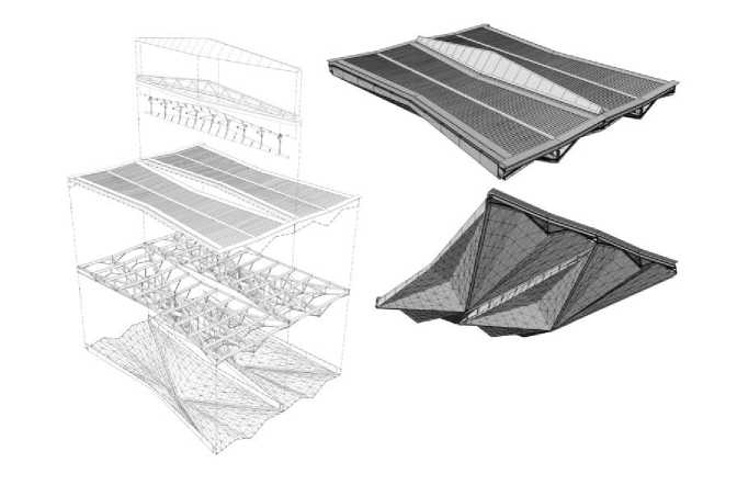
Figure 1. Roof light exploded model and perspective views [5]
Construction of Unique Buildings and Structures, 2015, №3 (30)
Configuration of supporting steel structure is caused by the unusual form of coating ceilings and roof lights in all spans. Due to its inherent vertical and torsional stiffness and alignment with the roof soffit geometry, the solution was planar trusses spanning longitudinally and diagonally between the roof columns. Planar trusses combine strength and stiffness with economy of materials and are therefore an efficient structural system for long spans.
The longitudinal trusses span a total distance of 270 m, comprised of 5 internal spans of 45 m with 2 cantilevers at the east and west facades of 22.5 m. The truss is continuous over the roof columns. Each 45 m span of the truss is broken down into 10 bays of 4.5 m – this matches the facade and roof-light glazing module of 2.25 m. The diagonal trusses follow the same logic, but due to their angle they span 48.5 m and division into 10 bays yields segments, which are 4.85 m long. Each planar truss varies in depth along its length to maximize efficiency whilst matching the roof soffit profile. Over supports where bending moments are largest the truss is 6.5 m deep, at mid-span, where bending moments are reduced due to the multi-span nature of the structure, the depth decreases to 1.5 m (longitudinal trusses) and 0.9 m (diagonal trusses), see figure 2.
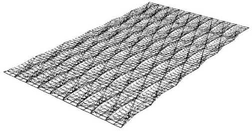
Figure 2. Structural scheme of the roof [5]
Diagonal bracing in the planar trusses provides coincident node points top and bottom for the restraint members and rafters. This arrangement also has a small structural benefit in that it shortens the length of the diagonals carrying the greatest compressive forces.
Roof load is transferred into the trusses by lightweight metal deck spanning 4.5 m (continuously over two or more spans) onto rafters, which run continuously over the top of the trusses. These also serve the purpose of restraining the top chords of the trusses, thereby reducing their effective length with respect to buckling and minimizing section sizes. The bottom chords of the trusses are restrained using struts connected to the rafters. These restraint members serve two other purposes; they prop the rafters reducing their span with respect to vertical loads and they conform to the architectural soffit, providing direct support to the finishes. Restraint forces transferred into the plane of the rafters are transmitted into the global stability system by means of plan bracing. The roof lights are supported on the tips of the rafter cantilevers, with an edge trimmer to partially distribute the load and unify deflections.
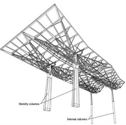
Figure 3. Stability and internal columns [5]
These trimmers also form part of the global restraint system, providing a load path for restraint forces between the truss compression chords and the stability columns.
The roof is supported by reinforced concrete columns located on a 45 m x 18 m grid. All roof columns are octagonal in section and taper from their base to head. They split into two main types: ‘stability’ and ‘internal’ columns as shown on figure 3.
The stability columns are located around the building perimeter and across the baggage void. They are designed as vertical cantilevers and transfer vertical loads from the roof and horizontal loads from the roof and facade to the foundations. Pinned connections at the head prevent roof-bending moments being transferred into the columns.
The internal columns spring from Level 3 of the internal frame and are designed to sustain only vertical load from the roof. To allow relative movement of the roof without bending moments being transferred, a pin bearing is located at each end of the column. Therefore, as the roof moves laterally or longitudinally, the column is free to rotate. The resultant horizontal component of the base reaction is resisted by the internal frame.
The roof-light structure (Figure 4) is designed to support its own self-weight and the dead and imposed loads from the glazing. By remaining independent from the primary roof structure it is unable to contribute to the overall system stiffness. The benefit is that undesirable global movements and stresses are not transferred into the glazing [5].
Access within the roof void is provided by an open grated walkway (refer to Figure 5). This allows access along the length of each roof void. The North and South roof modules have a different arrangement to the central roof voids due to the altered soffit shape in these modules.
The access walkway is formed from an open grating spanning 1.2 m between longitudinal steel sections, which span onto transverse steel sections supported by the roof primary steelwork. This walkway provides access to the roof soffit and the services located within the void [6].
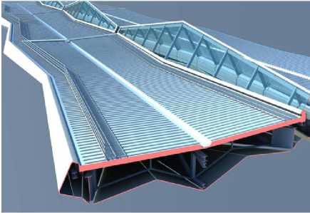
Figure 4. Roof-light structure [5]
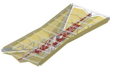
Figure 5. Roof walkways [5]
Calculation comparison
English engineers used the best European level in accordance to European Codes, ICAO Standards, and Russian National Codes for modelling the hall structure. Russian engineers took into consideration Russian National Codes, ICAO Standards and feasibility studies from English side. In both cases where conflict exists the higher-level standard takes precedence.
The Russian Codes do not have prescriptive guidance for robustness and disproportionate collapse. However, there is a local Saint Petersburg Territorial Building Standard which outlines progressive collapse design requirements for public high-rise buildings. There is also a Moscow State Construction Standard which outlines the progressive collapse requirements for high-rise buildings in Moscow [7-11].
English engineers used SAP 2000 software for modeling and calculating the structure, see Fig. 6. They took into account dead loads (loads of steel, ceiling, roof coating, technological, walkways and roof lights), live loads (snow and maintenance) and thermal loads. Wind loads were calculated empirically by testing the terminal in wind tunnel. Tests were conducted by BMT Fluid Mechanics Limited [12-14]. Additional research was made to define structure resistance in case of stability or internal column collapse.
Russian designers used SCAD Office software. They took into account the same load factors but without additional coefficients for adopting the requirements of European Codes. Wind loads were taken according to Russian Code. Modeling also included thermal impact. Modeled structure is presented on Figure 7.
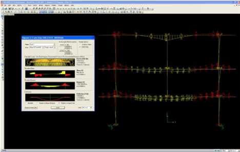
Figure 6. Roof structure in SAP software [5]
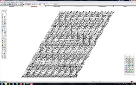
Figure 7. Roof structure in SCAD software
A detailed risk assessment developed by English designers outlines the robustness design risks to the project and allows the designer to understand the critical considerations with regard to both consequences of failure and likelihood of event [15, 16].
Russian engineers also thought about the fact that snow can be distributed uneven near the roof lights or on the half of a block span (Figure 8).
670 kg/m2
220 kg/m2 rrrmii bn
Figure 8. Uneven snow loads
Conclusion
New terminal at Pulkovo airport in Saint Petersburg was built as concrete-steel structure of specific shape, influenced by architectural requirements. The extreme demands on fabrication and assembly short time schedule had to be met in design in many ways. Regardless of these influences, a logical structure was created, in maximum respecting the structural behavior and using the spatial arrangement [17, 18].
Calculation result of Russian designers was different from their English colleagues. Difference is approximately 40 % in usage of materials and types of the steel. Cross-section of profiles is bigger and junctions are more complicated. In fact cost of construction is much higher [19-26].
Although both designs were accurate, sophisticated and labor-intensive customer decided to use construction documentation of Russian engineers based on English research. Despite high cost of steel structures and construction process, bearing capacity has more important influence on customers’ choice in Russia.
Список литературы Металлические конструкции кровли нового терминала аэропорта Пулково
- Art and architecture at Pulkovo airport URL:http://www.pulkovoairport.ru/en/about/art/(date of reference: 05.11.2014)
- Degertekin, S.O. Improved harmony search algorithms for sizing optimization of truss structures (2012) Comput Struct, 92 and 93, pp. 229-241.
- Baranovskiy M.Yu., Tarasov V.A. The standardized farm designs with 10 % slope for 24, 30, 36 meters span (2014) Construction of Unique Buildings and Structures, 7(22), pp. 92-106.
- Jankowska-Sandberg, J., Kolodziej, J. Experimental study of steel truss lateral-torsional buckling (2013) Engineering Structures, 46, pp. 165-172.
- Annet, N., Johnson, R. Boyle, G., Wilson, S., Harrold, R. Passenger Terminal Structural Design Philosophy Report (2011) Ramboll, pp. 28-59, pp. 132-143, pp. 198-519, pp. 569-700.
- Vatin N.I., Sinelnikov А.S. Long span footway bridges: cold formed steel cross-section (2012) Construction of Unique Buildings and Structures, 1, pp. 47-53. (rus)
- Perelmuter A.V., Pichugin S.F. Ob otsenke uyazvimosti stroitelnykh konstruktsiy (2014) Magazine of Civil Engineering, 5 (49), pp. 5-14. (rus)
- Tog’an, V. Design of planar steel frames using teaching-learning based optimization (2012) Eng Struct, 34, pp. 225-232.
- Allwood, R.J., Chung, Y.S. Minimum-weight design of trusses by an optimality criteria method (1984) Int J Numer Methods Eng, 20, pp. 697-713.
- Camp, C., Pezeshk, S., Cao, G. Optimized design of two-dimensional structures using a genetic algorithm (1998) J Struct Eng, 124(5), pp. 551-559.
- Venkayya, V.B., Knot, N.S., Reddy, V.S. Energy distribution in an optimal structural design (1969) AFFDL-TR-68-156, Flight Dynamics Laboratory, Wright-Paterson AFB, Ohio.
- Kuznetsov A.V. Building up a finite element model and calculating the wind load for large-span spatial hinged canopy of exhibition complex (2014) Construction of Unique Buildings and Structures, 7(22), pp. 24-35.
- Cook N.J. (1990) The designer's guide to wind loading of building structures. Part 2: Static structures. -London: Butterwords, 1990. -20 p.
- Bai, L., Zhang, Y. Nonlinear dynamic behavior of steel framed roof structure with self-centering members under extreme transient wind load (2013) Engineering Structures, 49, pp. 819-830.
- Adeli H, Kamal O. Efficient optimization of space trusses (1986) Comput Struct, 24(3), pp. 501-11.
- Camp, C.V., Farshchin, M. Design of space trusses using modified teaching-learning based optimization (2014) Original Research Article, Engineering Structures, 62-63, pp. 87-97.
- Jermoljev, D. Bratislava M.R. Štefánik Airport terminal hall steel structure (2012) Steel Structures and Bridges, 40, pp. 65-170.
- Baker W.F., Johnson, R.B., Korista, D.S., Sinn R.C. Art and Engineering in the Design of Steel Building Structures (1996) Advances in Steel Structures, ICASS '96, pp. 585-591.
- Miguel, L.F. Shape and size optimization of truss structures considering dynamic constraints through modern metaheuristic algorithms (2012) Expert Syst Appl, 39, pp. 9458-9467.
- Bram de Jager, Robert, E. Skelton Stiffness of planar tensegrity truss topologies (2006) International Journal of Solids and Structures, 43, pp. 1308-1330.
- Xianzhong, Z., Yiyi, C., Zuyan, S., Yangji, C., Dasui., W., Jian, Z. Prestressing and Loading Tests on Full-Scale Roof Truss of Shanghai Pudong International Airport Terminal (1999) Advances in Steel Structures, II, pp. 731-738.
- Mang, F., Wolfmüller, F., Yoon, W.Y. Theoretical And Experimental Investigations On The Tubular Structure Of Changi Hangar Roof, Singapore (1984) Welding of Tubular Structures, pp. 189-197.
- Ashford N.,Mumayiz S.,Wright P.,(2011: "Airport engineering, planning design and development of 21st century airports", John Wiley and Sons Co, New Jersey, USA
- General Books LLC (2010), "Airports in the Community of Madrid: Madrid-Barajas Airport, Madrid-Torrejon Airport, Cuatro Vientos Airport", LLC Books, Memphis, USA
- Иоскевич А.В., Савченко А.В. Сравнение ПВК SCAD Office и Лира-САПР на примере расчёта башни связи//Строительство уникальных зданий и сооружений. 2014. Vol. 10(25). Pp. 7-21. (rus)
- Гарифуллин М.Р., Семенов С.А., Беляева С.В., Порываев И.А., Сафиуллин М.Н., Семенов А.А. Поиск рациональной геометрической схемы пространственной металлической конструкции покрытия большепролетного спортивного сооружения//Строительство уникальных зданий и сооружений. 2014. № 2(17) С. 107-124. (rus).
