Method of Diagnostics of Multichannel Data Transmission System

Author: Anatolii Taranenko, Yevhen Gabrousenko, Oleksii Holubnychyi, Oleksandr Lavrynenko, Maksym Zaliskyi
Journal: International Journal of Image, Graphics and Signal Processing @ijigsp
Article in issue: 1 vol.17, 2025.
Free access
The redundancy of a multichannel data transmission system increases its reliability. During the operation of the system, it is necessary to diagnose and switch failed channels. To solve this problem, the set of input signals of the system is considered as a vector signal, whose scalar components are the coordinates of the vector in a given dimensional space. The diagnosis is performed using a scalar criterion, whose relative simplicity is ensured by the linearity of the signal transformations applied. To minimize the total probability of diagnostic error, the task of optimizing the tolerance on the diagnostic parameter is solved. The possibility of technical implementation of the proposed method is shown based on matrix transformations of the system's input and output signals. The system efficiency was assessed according to the "reliability-cost" criterion. Scientific novelty of the work consists in the fact that analytical expressions for matrix transformations of input and output vector signals of a multichannel data transmission system have been developed. Realization of these transformations provides diagnostics of the system according to the developed scalar criterion both in the test mode and in the mode of functioning as intended.
Diagnostics, Multichannel System, Vector Signal, Scalar Criterion, Reliability, Optimal Tolerance
Short address: https://sciup.org/15019648
IDR: 15019648 | DOI: 10.5815/ijigsp.2025.01.02
Text of the scientific article Method of Diagnostics of Multichannel Data Transmission System
Multichannel Data Exchange and Transmission Systems (MDTS) have a wide range of applications across various industries. Each application leverages the unique properties of different frequency bands to meet specific requirements, from high-speed data transmission to secure communication and precise sensing.
Mobile networks of all generations, satellite communications, navigation systems, as well as broadband wireless access systems like Wi-Fi, WiMAX, and other wireless internet services all use MDTS technologies [1]. Microwave MDTS are crucial for radar applications, including air traffic control [2], weather monitoring [3], military surveillance, and electronic warfare [4]. They serve as important components of automation for controlling machinery and processes remotely [5] and are widely used in applications like environmental monitoring [6].
Millimeter-wave MDTS [7] are used in autonomous vehicles for collision avoidance and navigation. Moreover, multichannel data transmission is of great importance in modern ultrawideband [8] and MIMO [9] systems. This is only a part of numerous MDTS applications. In many cases, MDTSs use reservation technology.
Any modern sophisticated MDTS is designed considering all phases of the system's life, with the most extended and crucial phase being the operation of the system [10]. During operation, the system must be maintained, which requires diagnostics of the system condition [11]. Thus, the diagnostics of the object is performed to determine its technical condition and includes processes of organizing and obtaining diagnostic information, transforming and transmitting this information, analyzing and processing the obtained diagnostic data, and making a decision about the object's condition [12]. There are physical and parametric diagnostic methods. Physical methods are based on the use of various physical phenomena accompanying the operable states of the object. Parametric diagnostic methods are based on measuring, appropriately transforming the measurement results, and subsequently evaluating the object's operability. Parametric methods fully correspond to the goal of verifying the correct functioning of an object when its purpose is to transform input signals into output signals. Such an object, in particular, is a multichannel data transmission system (MDTS). During diagnostics in the signal space, the correctness of the formation of the object's output signals is checked directly by their analysis, which is an advantage of the corresponding diagnostic methods. These methods can be divided into two groups.
The first group of methods uses a priori known information about signal characteristics, which is a disadvantage because the characteristics of the output signals depend on the characteristics of the input signals, whose behavior is often unknown in advance. This group of methods ensures insufficient completeness of control. The second group of methods, based on the use of algebraic invariants, is free from these disadvantages. By checking certain algebraic relationships (control conditions) that the set of the object's output signals must satisfy, supplemented if necessary with redundant signals, the invariant nature of the control conditions lies in the fact that in the absence of object failures, they must be met for any input signals at any time. The most well-known methods of this group include majority processing of redundant signals [13]. This method is widely used in practice but requires significant hardware redundancy when processing the scalar components of a multidimensional vector signal. This is due to the multiple reservations of identical transmission channels and the processing of redundant diagnostic information.
Thus, diagnosing the technical condition is an essential part of the technical operation and maintenance process of a multichannel data transmission system (MDTS). In multichannel systems, simultaneous operation of several channels makes it possible to obtain redundant information about the system's condition, opening up opportunities to improve diagnostic efficiency. Therefore, it is advisable to develop a method for using redundant diagnostic information based on simultaneous processing of output signals from channels that function during the system's operation. Errors in determining the operability of channels occur during diagnostics, leading to a deterioration in the system's operational characteristics and an increase in its failure probability. Minimizing this probability is achieved by optimizing the tolerance on the diagnostic parameter.
This article is dedicated to solving these problems by transforming the original space of MDTS input signals into a redundant space of signals and subsequently diagnosing the set of redundant output signals using the proposed scalar criterion. The Problem statement section contains the analysis of known works and generalized mathematical description of the process of diagnostics of the MDTS. The Problem solution section contains the choice of signal transformations necessary for diagnosing the MDTS, development of the scalar criterion of the diagnosed system operability, solution of the problem of optimizing the tolerance to the diagnostic parameter, as well as the description of the technical implementation of the proposed method. The Conclusions section summarizes the results obtained and directions for further research.
2. Problem Statement
The task of distributing reliability and redundancy, considering the optimal reservation strategy (active or cold reservation), is addressed in the article [14]. The authors proposed a reliability function for a cold reserved subsystem with an imperfect detector/switch, as well as an algorithm for solving the task based on a mixed integer nonlinear programming model. However, this work does not take into account the specifics of a multichannel data transmission system and does not address the issue of minimizing the total probability of diagnostic error.
In the work [15], the assessment of the reliability of a reserved system with imperfect fault coverage is investigated, where fault coverage refers to the system's ability to isolate and correctly respond to failures of reserved elements. Various fault coverage models are considered, algorithms for their separate evaluation are proposed, and their implementation feasibility is shown. However, the proposed algorithms do not consider the specifics of diagnosing a system designed for the simultaneous transmission of a set of information signals.
In the article [16], redundant systems consisting of several identical or similar components or modules are analyzed. It is noted that the system's reliability can be increased by using additional components or reservation, and a compromise between cost and reliability is considered to find an economically efficient optimal design. However, this work does not consider the specifics of diagnosing a redundant multichannel system and does not demonstrate ways to technically implement the diagnostic system.
The work [17] is dedicated to the study of a mathematical model for diagnosing a reserved system, considering the reliability characteristics of the diagnostic tool, the periodicity of control, and the imperfect quality of the system at the start of operation. The model's limitation is the cold reservation mode of redundant functional blocks. This does not allow the application of the obtained results for modeling the diagnostic process of a multichannel system where all redundant channels operate simultaneously.
The principle of increasing the probability of successful data transmission by sending multiple copies of the same message through independent channels is considered in the article [18]. Methods for designing communication protocols that use multiple packet transmissions considering the balance between stability/estimated performance and data transmission speed are proposed in there. In the work [19], possibilities of increasing the probability of timely and error-free delivery of packets by their redundant priority service are investigated, where the priority and redundancy multiplicity of the request are set depending on its allowable waiting time.
However, the works [18, 19] do not address the issue of failures in individual information transmission channels, which necessitates the development of appropriate diagnostic procedures to maintain the specified reliability of the multichannel data transmission system.
To solve these noted problems, initially, consider Fig. 1, which shows the structure of the parametric diagnostic process of an MDTS containing n main and m redundant (reserved) channels. In general, this process includes the following operations: forming stimulating signals and sending them to the diagnostic object, selecting and measuring diagnostic signals, obtaining an estimate of the measured diagnostic signal's correspondence to its true value, and making a decision about the object's condition.
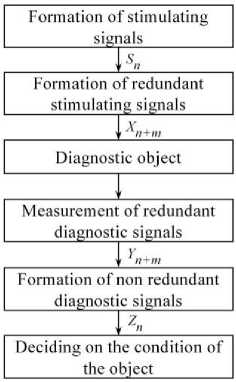
Fig. 1. Diagnostic process of the MDTS.
The designations of signals and operations shown in Fig. 1 have the following meanings. The vector stimulating signal
Sn = { Si, i = 1, n , n ^ 2} is transformed into a redundant stimulating signal
Xn+m = {xj , J = 1, n + m , m ^ 1}, each scalar component x contains information about all or some scalar components s of the signal S . Measured reactions of the diagnostic object
Yn+m ={ yj , J = 1, n + m ( are transformed into a non-redundant vector signal
Zn ={ z„ i = 1Tn }.(4)
To make a decision about the object's condition, it is necessary to preliminarily study the relationships between signals (1) – (4) in the presence of noise (measurement errors)
H n + m = { h j , J = 1, n + m ( .
Then it is necessary to develop an operability criterion for the MDTS, study its properties, and describe the practical implementation of such a diagnostic method. This article is dedicated to solving these tasks.
3. Problem Solution
From the considerations of linearity of transformations, which provides simplicity of their technical realization, we choose the following ways of formation of signals (2) and (4)
X
n + m
= AS n ,
7 = 4+ Y
Z n A Y n + m ,
where A is a rectangular matrix of coefficients a j ;, J = 1, n + m , i = 1, n , A + is a pseudo-inverse matrix calculated by the formula [23]
A += [ A T A ] - 1 A T, (8)
A T is a transposed matrix.
Under the condition of additivity of signal (2) and interference (5)
Y = X + H .
J n + m x n + m * n + m ,
and the equality of values h in (5)
hj = h ^ 0 , J = 1, n + m ,
it can be proved that the measured diagnostic signal Y n + m is a vector sum of orthogonal signals calculated by the formulas
F n + m = AZ n , (11)
G n + m = Y n + m — AZ n . (12)
The detailed derivation of (11) and (12) is of considerable length and is not covered in this paper. Fig. 2 shows a typical relationship between signals (2), (3), (11), (12) and interference (5).
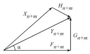
Fig. 2. Decomposition of the redundant diagnostic signal.
Taking into account that the rectangular triangle in Fig. 2 exists only when condition (9) is satisfied, let us write the scalar indicator of the MDTS performance in the form r = tga =
II G n + m il II Fn + m il
where G n + m il and IK+ m il are the norms of the signals Gn + m and F n + m •
Then the scalar criterion of the MDTS performance has the form of the inequality
r ^ ro, where r is a tolerance for the value of indicator (13).
For the case r = ro, let us determine the upper and lower permissible levels of interference (5) when condition (10) is fulfilled. After transformations using (6) – (13) we obtain where the unit matrix is
Let us denote the matrices
then (15) takes the form
r o
_ ||( E - AA +) Hn + m||
I X n + m + AA + H n + m|| ’
E = { eu = 1, ejt = 0, i = 1, n + m , j = 1, n + m , i ^ j } .
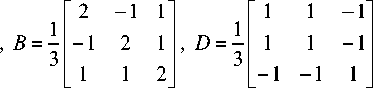
AA + = B = { b} ;, j = 1, n + m , i = 1, n + m } ,
E - AA + = D = { d ji , j = 1, n + m , i = 1, n + m } ,
r o
|| DHn + m||
||X n + m + BH n + m|| '
We pass to the squares of norms and write (19) in scalar form h22(Zdji)2 = ro2 Zxj2 + 2hZ(XjZbji) + h2Z(ZV •
j i L j j i j i _
From (20) we obtain g 2 h 2 - g 1 h - go = 0, where the coefficients g2 = P1 - P2ro2, g 1 = 2P3ro2, go = P4ro2,
P 1 = Z ( Z d ji )2, P 2 = Z ( Z Ь ,)\ p 3 = Z ( X j Z b ji ), p 4 = Z X j2 • ji ji j i j
Two solutions of the quadratic equation (21) are equal to the upper level and the lower level of interference (5), at which inequality (14) is still satisfied. Let us study the dependence of these solutions from the tolerance r o on the example of the MDTS of minimum dimension n = 2, m = 1. Let's
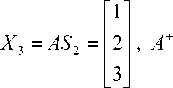
A =
S 2 =
then the signal (6) and matrices (8), (17), (18) are equal to
12 - 11
3 - 12 1
We compose (21)
P 1 = 1 , P 2 = 8 , P 3 = 6 , P 4 = 14 , g 2 = 0.333 - 2.667 r o 2 , g 1 = 12 r ° 2 , g o = 14 r o 2 ,
(0.333 - 2.667 r 2) h 2 - 12 r 2 h - 14 r o2 = 0.
Two solutions ( h , h ) of this quadratic equation are functions of the diagnostic tolerance r , which satisfies the condition (14). Taking into account (13), the corresponding angle a between vectors Yn+m = Y 3 and Fn+m = F 3, which are shown in Fig. 2, is equal to a = arctg ro .
Fig. 3 shows the dependence of solutions ( h , h2 ) on the value of the angle a .
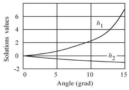
f ig . 3. d ependence of solutions ( h , h ) on the angle α value.
For example, a = 5 O , ro = 0.087, then h = 0.75 , h2 = - 0.46.
Let us consider the case when the interference level is located between the solutions of (21), i.e. h e [ h , h 2 ] . Let the interference vector (5) be equal to
H3 ={ hj = 0.7, j = 1,3 }, then signals (11), (12) and their norms are equal to
|
T47' |
' 0.23 ' |
||
|
F 3 = |
2.47 |
, G 3 = |
0.23 |
|
_ 3.93 _ |
- 0.23 |
||F 3|| = 4.87 , | G 3|| = 0.4.
According to criterion (14)
r= II G + m il = I F + m il
= 0.082 < ( ro = 0.087)
a decision is made on the operability of the MDTS.
Let us consider the case when the interference level exceeds the values of solutions of (21), i.e. h й [ h , h 2 ] . Let the interference vector (5) be equal to
H 3 ={ hj =-0.5, j = 1,3 }, then signals (11), (12) and their norms are equal to
|
0.67 |
- 0.17 |
||
|
F 3 = |
1.67 |
, G 3 = |
- 0.17 |
|
2.33 |
0.17 |
||F3W = 2.94, G з|| = 0.29.
According to criterion (14)
r = М+4 = 0.099 > (r = 0.087) Fn+m ° a decision is made that the MDTS is inoperable.
To find the optimal tolerance, let us determine the diagnostic confidence parameters based on criterion (14). The numerical value of the indicator (13) is calculated through the positive norms of signals G and F , so the conditions of operability and inoperability of the MDTS will be written in the form r e [ 0, r ] and r e ( r , ® ] respectively, where the true value of r is a random variable due to destabilizing factors.
When diagnosing an MDTS, we can make two mutually exclusive hypotheses: R – the system is operable, and R – the system is inoperable. A priori probabilities of these hypotheses are calculated by the following formulas ro
P ( R 1 ) = J f l ( r ) dr , (23)
0 ^
P ( R 2 ) = J f 1 ( r ) dr , (24)
ro where f (r) is the distribution density of the random variable r.
When checking the condition (14), errors in determining the state of the MDTS are possible due to the finite accuracy of the measuring instruments. Suppose that the measurement error 3 of the indicator r is an additive random variable, then the measurement result is equal to
r * = r + 3 . (25)
According to the results of the measurement of the r * value, we can make four hypotheses St , i = 1,4 , which are the complete group of incompatible events with probabilities of
P ( S 1 ) = P ( r e [0, r o ] n r * e [0, r o ]), P ( S 2 ) = P ( r e [ r , , ^ ] n r * e [ r , , ^ ]),
P ( S 3 ) = P ( r e [0, r , ] n r * e [ r , , ® ]), P ( S 4 ) = P ( r e [ Г о , ® ] n r * e [0, r o ]), (26)
E p ( S i ) = 1. i = 1
Probabilities ar of "false failure" and pr of "undetected failure" are calculated by the following formulas ar = P(S3) = J[ J f 2 (3)d3]f1 (r)dr,(27)
0 Г, - Г er = P(S4) = J[ oJ f 2 (3)d3]f1 (r)dr,(28)
ro where f2 (3) is the distribution density of the measurement error.
Let us determine the diagnostic reliability parameters under the condition that the distribution densities f (r) and f2 (3) are described by exponential and step-exponential laws respectively f1(r) = λe-λr,(29)
f2(ϑ)=ϑve-ϑ.(30)
v !
Let λ = 2 , v = 1, then after substituting (29) and (30) into (27) and (28) we obtain
αr =2roe-ro, βr =e-2ro.(31)
Fig. 4 shows the dependence of probabilities α and β , as well as the total probability of error Q = α + β on the tolerance r . Curves 1 and 2 correspond to probabilities α and β , which are calculated by formulas (31), curve 3 corresponds to the total probability Q .
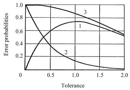
Fig. 4. Dependence of error probabilities on the tolerance r value (SNR < 1).
In this case, there is no value of r o , optimal by the criterion of minimum total probability of error Qr . This is due to the fact that in the process of measuring the value r the signal-to-noise ratio is equal to
2 - 2
SNR = σ r = λ = 0.125 < 1.
σ ϑ 2 v + 1
Let us determine the diagnostic reliability parameters under the condition that the distribution density f ( r ) is described by the law (29) with λ = 1, and the density f ( ϑ ) is described by Rayleigh's law
ϑ 2 f 2 ( ϑ ) =ϑ e 2 .
After substituting such f ( r ) and f ( ϑ ) into (27) and (28) we obtain
, 1 — 7'
αr =2.066e-ro[0.682-erf( ro)] , βr = 0.343e-ro, r2r
x where erf (x) = ∫ e -t dt is error function.
π 0
Fig. 5 shows the dependence of probabilities α , β , and the total probability of error Q = α + β on the tolerance r . Curves 1 and 2 correspond to probabilities α and β , which are calculated by formulas (33), curve 3 corresponds to the total probability Q .
In this case, the signal-to-noise ratio is
SNR = -^ ^э
к- 2
0.5(4 -п )
= 2.32 > 1,
and the value of the tolerance optimal by the minimum criterion Qr , is equal to roopt = 0 .
Considering Fig. 2 and Fig. 3, the result obtained means the following. In the absence of interference (measurement errors), when H n + m = { h j = 0, j = 1, n + m } , the norm || Gn + m | = 0 and vectors Yn + m and Fn + m coincide, i.e., α = 0. Under interference conditions, these vectors do not coincide, and the validity of the MDTS performance evaluation depends only on the accuracy of the calculation of the criterion (14) at ro = roopt = 0.
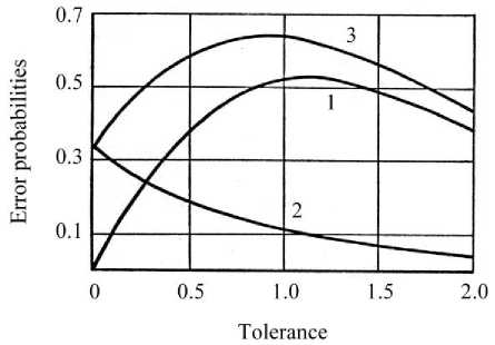
Fig. 5. Dependence of error probabilities on the tolerance r value (SNR > 1).
Under condition r > ro , the signal (7) corresponding to the operable MDTS is calculated by the formula
Z n = F [ A T UA ] - 1 A T UF -1 Yn + m ,
where F are conversion functions of signals in MDTS channels, F - 1 are inverse conversion functions, U is a diagnostic matrix, which is used to search for failed MDTS channels.
An important advantage of the proposed method is the possibility of functional (i.e., non-test) diagnostics of data transmission channels in the process of the MDTS operation as intended. In this case, the input signals of the channels are used as stimulating ones, and the output signals as diagnostic ones.
Fig. 6 shows the structure of the functional diagnosis system using formula (34).
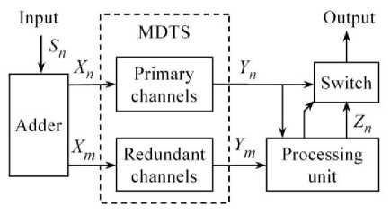
Fig. 6. Diagnostic system structure.
The input vector signal S is fed to the adder, which realizes the formula (6) and forms the vector signal X n + m = X n & X m .
In accordance with formula (9), a vector signal Yn+m = Yn & Ym is formed at the output of the MDTS.
The processing unit calculates the signal Z according to formula (34) and checks criterion (14). In this case, the matrix U in formula (34) is equal to the unit matrix (16). Fulfillment of inequality (14) corresponds to an operable state of the MDTS, with the signal passing to the switch output.
Non-fulfillment of inequality (14) is a sign of failure of MDTS channels. The search for these channels consists in finding the coefficients of the matrix U in formula (34), which are equal to {uit = 0}, where i = 1, n + m are indices (numbers) of the failed channels. After setting such coefficients, inequality (14) is fulfilled. The signal Z is formed on the basis of the redundant signal Y and is equal to the signal Y of the operable MDTS, so the signal Z passes to the switch output instead of the signal Y .
Such construction of the diagnostics system is reasonable for the existing MDTS. For the designed system, the separation of channels into the main part and the redundant part is not required, because all components of the redundant vector signal Y are equiable during the formation of the vector signal Z . In this case it is possible to exclude the switch and use the signal Z as an output signal.
Let us evaluate the efficiency of the proposed method of diagnostics. For this purpose, let's consider two variants of using redundant channels presented in Fig. 7.
Fig. 7. Options of the redundant MDTS.
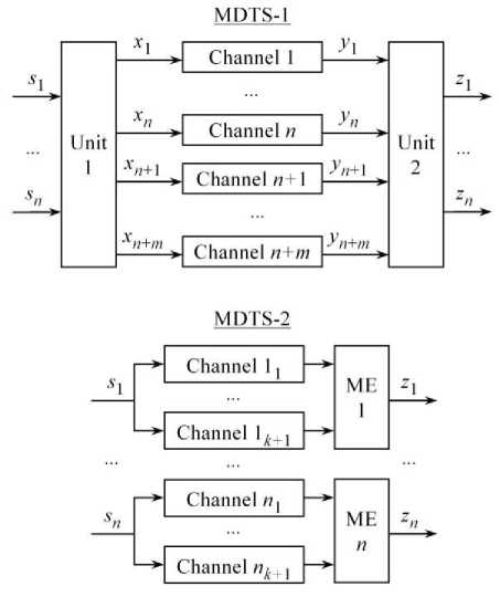
In the MDTS-1, units 1 and 2 perform calculations according to (6) and (34), respectively.
In the MDTS-2, redundant diagnostic signals are processed by majority elements (ME).
The condition of reliability efficiency of MDTS-1 compared to MDTS-2 is as follows
Q 1 + Q nm + Q 2 < n ( Q 1 k + Q m ),
where Q , Q , Q are failure probabilities of unit 1, unit 2, and majority element, Q is failure probability of all redundant channels of MDTS-1, Q is probability of failure, at which there is a complete loss of one redundant channel data in the MDTS-2, it's equivalent to the failure of this system as a whole.
The failure probabilities of a set of channels are calculated by the formulas
m + n
Q nm = E C П + m q(1 - q )
I m + n — i
i = m + 1
k + 1
Q i k = E c k + i q(1 - q ) k + 1 — i ,
k l+1
where q is probability of failure of one unreserved channel.
Further, we take the probability q as a base value for calculating of failure probabilities Q , Q , and Q in (35). For this purpose we use the approximating formulas
Q1 = a ( n + 1) m b 1 q , Q 2 = a 2( n + 1) m b 2 q, Q m = a з ( k + 1) b 3 q ,
where a , a , a are normalization parameters, b , b , b are parameters of the reliability change rate of corresponding blocks with the growth of m and k .
Substituting (36), (37), and (38) into (35), we perform successive transformations and find the boundary value m , at which MDTS-1 is more effective by reliability compared with MDTS-2
m i <---- 1
a1 a 2
n q (n +1)
k + 1
£ C k + 1 q i (1 - q ) k + 1 - i + a 3 ( k + 1) b 3 q i = k + 1
b 1 + b 2
The cost-effectiveness condition of MDTS-1 compared to MDTS-2 is as follows
V 1 + ( n + m ) V + V 2 < n [ ( k + 1) V + V M ] , (40)
where V , V , V are costs of unit 1, unit 2, and majority element, V is the cost of one unreserved channel. For V , V , V we use similar approximating formulas
V 1 = c 1 ( n + 1) m d 1 V , V2 = c 2( n + 1) m d 2 V ,
VM = cз(k +1)d3 V, where c - c3 and d3 - d3 are similar to the parameters aj - a3 and b - b3 in (38).
Substituting (41) into (40), we perform successive transformations and find the boundary value of m , at which MDTS-1 is more cost effective than MDTS-2
m 2< <
n 3 [ k + c 3( k + 1) d 3 ] 3 27 cc 2 ( n + 1)2
1 + d 1 + d 2
Calculation of m by (39) and m by (42) provides the choice of the number of redundant channels m = min( m. , m2 ) , at which MDTS-1 is more efficient than MDTS-2 in terms of reliability and cost at the same time.
Table 1 shows an example of calculating such boundary values under conditions: n = 3 , q = 10 - 3, at = 0.33, i = 1,3 , b i = d i = 1, i = 1,3 , c 1 = c 3 = 0.01, c 2 = 0.1.
Table 1. Boundary Values of the Number of Reserve Channels
|
n = 3 |
k |
||
|
2 |
4 |
6 |
|
|
Integer m 1 = m |
6 |
11 |
15 |
|
Integer m 2 |
8 |
16 |
24 |
According to this table, Fig. 8 shows the dependence of the number of redundant channels N = n + m in the MDTS-1 and N = n ( k + 1) in the MDTS-2 from the multiplicity k of majoritarian processing.
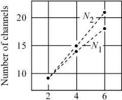
Processing multiplicity
Fig. 8. The number of channels in the MDTS.
The graphs show that at k > 2 the MDTS-1 provides a gain not only in reliability and cost, but also in the number of required redundant channels.
In practice, the values of the approximation parameters (38) and (41) can be obtained by analyzing the information from manufacturers of MDTS, as well as by processing operational data for systems of the corresponding type.
As mentioned above, an advantage of the MDTS-1 is the ability to diagnose data transmission channels while the system is operating as intended. In this case, the input signals of the channels are used as stimulating signals and the output signals are used as diagnostic signals. This improves the reliability of channel transformations of the vector signal Xn + m .
For example, in the MDTS-1 (Fig. 7) given N = n + m = 9 (Fig. 8), to generate the output signal Zn = Z 3 it is enough to have any three scalar components of the redundant signal Yn+m = Y 9. Failure of the MDTS-1 occurs after the failure of any seven redundant channels.
In the MDTS-2 (Fig. 7) given N2 = n ( k + 1) = 9 = N , failure of any three channels from 9, one for each component, is acceptable. However, after the failure of any fourth channel, the failure of the MDTS-2 occurs. In this case, the MDTS-1 is 7 / 4 = 1.75 times more efficient than the MDTS-2 in terms of reliability in performing of channel transformations. This is due to the fact that in the MDTS-1 all components of the redundant signal Yn+m = Y9 are equally valid in the formation of components of output signal Zn = Z3 , since each component of the redundant signal Xn+m = X ? is a linear combination of components of the input signal Sn = S 3.
Thus, as a result of solving the problem set, a method of diagnosing a redundant multichannel system designed for transmission of data, which are represented by a vector signal, has been developed. The method is characterized by the fact that obtaining of diagnostic information is provided by means of formation and processing of redundant stimulating and diagnostic signals. A simple scalar criterion for the performance of such a system based on matrix transformations of output signals of redundant data transmission channels has been proposed. The developed technology of diagnostics is expedient to apply at maintenance of ground [20], airborne [21] and combined [22] multichannel redundant data exchange systems.
4. Conclusions
A method of diagnosing a redundant multichannel data transmission system has been proposed. This method is based on the representation of a set of input and output signals of the system in the form of vector signals. The relative simplicity of the necessary computational procedures has been achieved by applying linear matrix transformations of these signals. A rather simple scalar parameter for evaluating the performance of the system has been developed. The problem of finding the tolerance for this parameter, optimal according to the criterion of the minimum total probability of error, has been solved. It was shown that the reliability of diagnostics results is conditioned by the accuracy of hardware realization of applied functional transformations of redundant signals.
The diagnostic system realizing the proposed method provides the following advantages: diagnostics and restoration of failed data transmission channels are performed without interrupting the operation of the multichannel system and without an additional source of stimulating signals, diagnostics is performed using only the output redundant vector signal, there is a reserve of channels, which increases the reliability of the multichannel system.
Future promising research can be conducted in the following directions: investigation of the process of diagnosing a multichannel data transmission system under multiplicative interference, optimization of the tolerance to the diagnostic parameter for a wider class of laws of distribution of results and errors of measurement of diagnostic parameters, as well as detailing the structure of functional blocks that implement the proposed method.
References Method of Diagnostics of Multichannel Data Transmission System
- R. L. Freeman, Telecommunication System Engineering, 4th ed., NY: Wiley, 2015, 1024 pp.
- F. J. Yanovsky, “Modern radar systems in Ukraine,” 16th International Radar Symposium (IRS), Dresden, Germany, 2015, pp. 990–997, doi: 10.1109/IRS.2015.7226368.
- F. J. Yanovsky, H. W. J. Russchenberg and C. M. H. Unal, “Retrieval of information about turbulence in rain by using Doppler-polarimetric Radar,” in IEEE Transactions on Microwave Theory and Techniques, vol. 53, no. 2, pp. 444–450, Feb. 2005, doi: 10.1109/TMTT.2004.840772.
- “Electromagnetic warfare,” NATO. March 22, 2023. Archived from the original on June 8, 2023. Retrieved September 21, 2023.
- O. Sushchenko et al., “Design of robust control system for inertially stabilized platforms of ground vehicles,” IEEE EUROCON 2021 - 19th International Conference on Smart Technologies, Lviv, Ukraine, 2021, pp. 6–10, doi: 10.1109/EUROCON52738.2021.9535612.
- F. Yanovsky, “Inferring microstructure and turbulence properties in rain through observations and simulations of signal spectra measured with Doppler-polarimetric radars,” in Book: Polarimetric Detection, Characterization and Remote Sensing, Springer, NATO Science for Peace and Security Series C: Environmental Security, 2011, 117, pp. 501–542.
- F. Yanovsky, “Millimeter-Wave Radar: Principles and Applications,” 72 pp., Ch. 10 in Book: Millimeter Wave Technology in Wireless PAN, LAN, and MAN, Auerbach Publications CRC Press, 2008, 464 pp. ISBN: 9780849382277.
- F.J. Yanovsky, V.E. Ivashchuk and V.P. Prokhorenko, “Through-the-wall surveillance technologies,” 2012 6th International Conference on Ultrawideband and Ultrashort Impulse Signals, Sevastopol, Ukraine, 2012, pp. 30–33, doi: 10.1109/UWBUSIS.2012.6379723.
- R.B. Sinitsyn and F.J. Yanovsky, “MIMO radar copula ambiguity function,” 2012 9th European Radar Conference, Amsterdam, Netherlands, 2012, pp. 146–149.
- O. Solomentsev, M. Zaliskyi, T. Herasymenko, O. Kozhokhina and Yu. Petrova, “Efficiency of operational data processing for radio electronic equipment,” Aviation, vol. 23, issue 3, 2019, pp. 71–77, doi: 10.3846/aviation.2019.11849.
- O. C. Okoro, M. Zaliskyi, S. Dmytriiev, O. Solomentsev and O. Sribna, “Optimization of maintenance task interval of aircraft systems,” International Journal of Computer Network and Information Security, vol. 14, no. 2, 2022, pp. 77–89, doi: 10.5815/ijcnis.2022.02.07.
- O. Solomentsev, M. Zaliskyi, T. Herasymenko and Y. Petrova, “Data processing method for deterioration detection during radio equipment operation,” IEEE Microwave Theory and Techniques in Wireless Communications (MTTW), Riga, Latvia, 2019, pp. 1–4, doi: 10.1109/MTTW.2019.8897232.
- Majority Signal Voting, https://gssc.esa.int/navipedia/index.php/Majority_Signal_Voting.
- H. Kim and P. Kim, “Reliability–redundancy allocation problem considering optimal redundancy strategy using parallel genetic algorithm,” Reliability Engineering & System Safety, vol. 159, 2017, pp. 153–160, doi: 10.1016/j.ress.2016.10.033.
- A.F. Myers and A.B. Rauzy, “Assessment of redundant systems with imperfect coverage by means of binary decision diagrams,” in Reliability Engineering & System Safety, vol. 93 (7), 2008, pp. 1025–1035, doi: 10.1016/j.ress.2007.05.002.
- P. Zhu, R. Lv, Y. Guo and S. Si, “Optimal design of redundant structures by incorporating various costs,” IEEE Transactions on Reliability, vol. 99, 2018, pp. 1–12, doi: 10.1109/TR.2018.2843181.
- A.G. Taranenko, Y.I. Gabrousenko, A.G. Holubnychyi and I.A. Slipukhina “Estimation of redundant radionavigation system reliability,” 2018 IEEE 5th International Conference on Methods and Systems of Navigation and Motion Control, MSNMC, 2018, pp. 195–197, doi: 10.1109/MSNMC.2018.8576282.
- A.R. Mesquita, J.P. Hespanha and G.N. Nair, “Redundant data transmission in control/estimation over lossy networks,” Automatica, vol. 48, issue 8, 2012, pp. 1612–1620, doi: 10.1016/j.automatica.2012.06.009.
- I.A. Slastikhin and V.A.Bogatyrev, “Redundant priority maintenance in the multi-channel systems,” 2018 Wave Electronics and its Application in Information and Telecommunication Systems (WECONF), 2018, pp. 1–5, doi: 10.1109/WECONF.2018.8604301.
- S. Ma et al, “Overview of 5G multi-channel redundant transmission technology,” Telecommunications Science, vol. 40, issue 5, 2024, pp. 1–22, doi: 10.11959/j.issn.1000-0801.2024026.
- F. J. Yanovsky, “Evolution and prospects of airborne weather radar functionality and technology,” 2005 18th International Conference on Applied Electromagnetics and Communications, Dubrovnik, Croatia, 2005, pp. 1–4, doi: 10.1109/ICECOM.2005.204987.
- S. Gulgonul, E. Koklukaya, I. Erturk and A. Y. Tesneli, “Communication satellite payload redundancy reconfiguration,” 2012 IEEE First AESS European Conference on Satellite Telecommunications (ESTEL), Rome, Italy, 2012, pp. 1–4, doi: 10.1109/ESTEL.2012.6400090.
- Moore–Penrose inverse: https://en.wikipedia.org/wiki/Moore–Penrose_inverse
