Method of relative magnitudes for calculating magnetic fluxes in electrical machine

Author: Zakharzhevskii Oleg A.
Journal: Инженерные технологии и системы @vestnik-mrsu
Section: Машиностроение
Article in issue: 1, 2018.
Free access
Introduction. The article presents the study results of the model of an asynchronous electric motor carried out by the author within the framework of the Priorities Research Program "Research and development in the priority areas of development of Russia's scientific and technical complex for 2014-2020". Materials and Methods. A model of an idealized asynchronous machine (with sinusoidal distribution of magnetic induction in air gap) is used in vector control systems. It is impossible to create windings for this machine. The basis of the new calculation approach was the Conductivity of Teeth Contours Method, developed at the Electrical Machines Chair of the Moscow Power Engineering Institute (MPEI). Unlike this method, the author used not absolute values, but relative magnitudes of magnetic fluxes. This solution fundamentally improved the method's capabilities. The relative magnitudes of the magnetic fluxes of the teeth contours do not required the additional consideration for exact structure of magnetic field of tooth and adjacent slots. These structures are identical for all the teeth of the machine and differ only in magnitude. The purpose of the calculations was not traditional harmonic analysis of magnetic induction distribution in air gap of machine, but a refinement of the equations of electric machine model. The vector control researchers used only the cos(6) function as a value of mutual magnetic coupling coefficient between the windings. Results. The author has developed a way to take into account the design of the windings of a real machine by using imaginary measuring winding with the same winding design as a real phase winding. The imaginary winding can be placed in the position of any machine windings. The calculation of the relative magnetic fluxes of this winding helped to estimate the real values of the magnetic coupling coefficients between the windings, and find the correction functions for the model of an idealized machine. Modeling in the MATLAB showed that the refinement model of the idealized machine makes the electromagnetic processes similar to the processes of the real machine. Discussion and Conclusions. The use of the proposed correction functions does not require the alteration of the vector control systems. The correction functions make the Park's and Clark's transformations more exact. The model of machine becomes more accurate and the processes taking place inside it coincide with real machine processes. The control of the electric machine becomes more precise.
Magnetic fluxes, calculating magnetic fluxes, electric machine, clark''s and park''s transformations, method of relative magnitudes
Short address: https://sciup.org/14720284
IDR: 14720284 | UDC: 621.313.3 | DOI: 10.15507/0236-2910.028.201801.062-076
Метод относительных величин для расчета магнитных потоков в электрических машинах
Введение. Статья знакомит с результатами исследований модели асинхронного электродвигателя, выполненных автором в рамках целевой программы «Исследования и разработки по приоритетным направлениям развития научно-технологического комплекса России на 2014-2020 годы». Материалы и методы. В системах векторного управления, как правило, используется модель идеализированной асинхронной машины (с синусоидальным распределением магнитной индукции в воздушном зазоре), изготовить обмотки которой не представляется возможным. Основой представленного в статье метода расчета стал метод проводимостей зубцовых контуров, разработанный на кафедре электрических машин ФГБОУ ВО «Национальный исследовательский университет "МЭИ"». В отличие от данного метода, в работе были использованы не абсолютные, а относительные величины магнитных потоков, что принципиально улучшило возможности метода. Для относительных величин не требуется дополнительное рассмотрение точной картины магнитного поля зубца и соседних пазов, поскольку данные картины для всех зубцов машины отличаются только величиной. Целью расчетов стал не традиционный гармонический анализ распределения магнитной индукции в воздушном зазоре машины, а уточнение уравнений модели электрической машины. Исследователи векторного управления использовали только функцию cos(d) как величину коэффициента взаимной магнитной связи между обмотками. Результаты исследования. Был разработан способ учета конструкции обмоток реальной машины путем использования (воображаемой) измерительной обмотки, имеющей такую же конструкцию, что и реальная фазная обмотка. Расчет относительных магнитных потоков этой обмотки, которая может помещаться в позицию любой из обмоток машины, позволил рассчитать реальные величины коэффициентов магнитной связи обмоток и найти поправочные функции к модели идеализированной машины. Моделирование в MATLAB показало, что предложенное уточнение модели идеализированной машины делает электромагнитные процессы подобными процессам реальных машин. Обсуждение и заключения. Важно, что применение предложенных поправочных функций не требует переработки созданных ранее систем векторного управления. Данные функции также уточняют преобразования Парка и Кларк. Модель электрической машины становится более точной, a процессы в ней - соответствующими процессам в реальной машине; появляются возможности для более верного управления электрической машиной.
Text of the scientific article Method of relative magnitudes for calculating magnetic fluxes in electrical machine
The peculiarity of all electric machines is that when the current flows through the machine winding, the distribution of the magnetic induction in the air gap differs from the sinusoidal shape. That is why the most widespread method for studying processes in electric machine remains the method of harmonic analysis of the non-sinusoidal distribution of magnetic induction in the air gap of the machine. The disadvantage of this method is a usage of virtually the same model of an idealized electric machine, but only this model is used for each harmonic component separately.
In general, a three-phase electric machine is described by a system of nonlinear differential equations of the electric and magnetic circuits of the stator and the rotor for the instantaneous currents, voltages and magnetic flux linkages of the windings according to Kirchhoff’s current and voltage laws, taking into account the rotation of the rotor with respect to the stator. For such spatial systems of equations A. Blondel has developed a method of two reactions in 1893 [1]. The effectiveness of the two reactions method is that it has helped to solve the system of nonlinear differential equations of a three-phase electric machine by converting it into simpler and more convenient for analysis two-phase system of equations. This method was improved by well-known scientists (R. H. Park [2], A. A. Gorev [3], E. Clarke1). The method of two reactions is based on the transformations of vectors in linear space and corresponds to the cosine transformation of vectors. In fact, the method of two reactions uses the model of an idealized electric machine.
To achieve more dynamic and deep vector control of electric machine a model of an idealized machine is not enough,
Том 28, № 1. 2018
and rather more accurate model of a real machine is required that corresponds to the distribution of magnetic induction in air gap according to the design of windings and of machine’s magnetic system.
The author has developed a method to refine the model the parameters of idealized electric machine. In this article, the author has described his calculating method of magnetic fluxes of electrical machines, which serves as the basis for refinement of an idealized electric machine model. It is important for practice that the application of these correction functions in the drive control system does not require the alteration of the previously created control systems.
Literature review
As the basis for calculating the distribution of magnetic induction along the air gap of a real machine, the author has applied the Method of Conductivity of Teeth Contours (MCTC), developed at the Department of Electrical Machines of Moscow Power Engineering Institute (MPEI)1 [2–3]. According to the MCTC, the phase winding of the machine was replaced by a set of windings (“teeth contours”) creating the same distribution of magnetic induction in the air gap, as well as the distribution of original phase winding of the machine. In2–3, the absolute values of the magnetic fluxes of the windings were used. Then obtained magnetic induction distributions were subjected to traditional harmonic analysis for the study of electromechanical processes.
In general, a three-phase electric machine is described by a system of nonlinear differential equations of the electric and magnetic circuits of the stator and rotor for the instantaneous currents, voltages and magnetic flux linkages of windings according to Kirchhoff’s current and voltage laws, taking into account the rotation of the rotor with respect to the sta- tor4–11 [4–7]. The intermediate values between the currents of the windings are the magnetic flux linkages of the windings. The magnetic coupling is created by the design of the windings and the magnetic system and demonstrated in the equation as mutual inductances between the windings.
All the mutual inductances between the windings are function of the electric angle of the rotor rotation with respect to the stator. This function is different for various types of windings4–7. So machines with different winding design will react differently to the same control method, when the power supplies made one the same impact on stator windings. The fact, now only one model of an idealized asynchronous machine is used in electric drive control and during the process of modeling. It shows that there is a necessity to take into account the design of the real machine windings.
The calculating method of magnetic fields of electric machines was thoroughly described in the work5. In this work, the concept of Winding Function Theory (WFT) was introduced for the first time and the method of its application was described. The basis of the WFT was the law of total current, Ampere’s law and Gauss’s theorem, studied in the discipline the theoretical bases of electrical engineering. In this work, an example of the calculation for the WFT was given and it was pointed out the difference of windings functions for various types of windings. The usage
MORDOVIA UNIVERSITY BULLETIN 1^1 of the Fourier series (harmonic analysis) for describing the non-sinusoidal distribution of magnetic induction in the air gap of an electric machine has been proposed for the universal application of the WFT in the work5, and was made the concept of mutual magnetic conductivity between windings. There also introduced the concept of an idealized electric machine (for each of the harmonics separately).
The method of the WFT is widely used by developers of vector control systems of electrical machines8–10 [4; 8]. The WFT developers offer various versions of integral expressions for calculating the absolute value of the magnetic flux of winding or the inductance of winding of particular electrical machine. In these integral expressions, spatial functions were applied for the mutual magnetic conductivity between the windings. These spatial functions are unknown in advance, and at the same time they depend on the angle of the rotor rotation with respect to the stator. It is very difficult to use the proposed algorithms in the model of an electric machine and in the control system of the electric drive.
Some researchers have supposed to use the correction functions to the mutual inductances between windings in the model of an asynchronous machine12 [8]. These correction functions were not obtained in complete form. Therefore, the WFT remained in the algorithms form of calculating mutual magnetic fluxes for each particular electric machine. The usage of the model of an idealized electric machine continues in the WFT.
Methods of the Winding Field Theory have been started to use for calculating of the magnetic fields of electric machines as the first electronic computers had been invented13–17 [2–3]. To simulate the machine's magnetic field, various mathematical methods were used ‒ the finite element method, the grid method, the conformal mappings method, discrete electrical models equivalent to the machine’s magnetic field. The use of computer programs of magnetic fields modeling in the WFT did not give generalized mathematical expressions for the refinement of the electric machine model18–19 [9–10]. These techniques have given a useful result for particular electrical machine.
The scientists of the Department of Electrical Machines of Moscow Power Engineering Institute (MPEI) have created the MCTC for calculating the magnetic fluxes of electric machine during the appearance of semiconductor converters for the control of electric machine [2–4]. With reference to the MCTC, they have mastered the methods of modeling for the control of electric machine and new computer methods for calculating magnetic fields.
The information search has showed that at present the research is being conducted in the direction of refinement of the electric machine model according to the design of the windings of the real electric machine.
Materials and Methods
The basic processes in the mathematical model of a three-phase asynchronous machine were described by the equations of mutual inductive coupling between three phase windings of the stator and three phase windings of the rotor13–17; 20‒21 [1–4]. In order for the reader to understand the meaning of calculating the parameters of the model of an asynchronous machine, its system of equations has given below. It connected the voltages and currents of all phase windings.
In the text below: instantaneous values of voltages u , currents i and flux linkages of windings Ψ , active resistances of windings R , inductance L and mutual inductances between windings M . The indices of the quantities have shown the belonging to the stator windings of phases A , B and C or to the windings of the phase rotor a , b and c . For example, ua has the instantaneous voltage value of phase a rotor; MВс – mutual inductance between the winding of the phase B of the stator and the winding of the phase c of the rotor. The matrices of the corresponding quantities were enclosed in a square brackets, the superscript D of the matrices has shown that the matrix is diagonal.
-
13 Clarke E. Circuit analysis of A-C power systems.
-
14 Ivanov-Smolenskiy A. V. [Electrical machinery].
-
15 Ivanov-Smolenskiy A. V., Abramkin Yu. V., Vlasov A. I., Kuznetsov V. A. A universal method for calculating electromagnetic processes in electrical machines.
-
16 Kopylov I. P. [Mathematical modeling of electrical machines].
-
17 Schmitz N. L., Novotny D. W. Introductory electromechanics.
-
18 Schumann C., Müller T., Stein E., Pacas M. Analytical calculation of the induced EMF in PM-machines with arbitrary arranged surface mounted magnets using the winding function theory. In: Proceedings of the 2014 International Conference on Electrical Machines (ICEM); 994–1000. DOI: 10.1109/ ICELMACH.2014.6960302
-
19 Igelspacher J., Hecker Q., Herzog H.-G. Simulation of an axial-flux induction machine with squirrel cage based on the winding function theory. In: Electrical Systems for Aircraft, Railway and Ship Propulsion. 2012; 1–6. DOI: 10.1109/ESARS.2012.6387428
-
20 Boldea I., Nasar S. A. The induction machine handbook.
-
21 Available at: http://people.ece.umn.edu/users/riaz
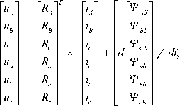
During the research, the author found that the more universal parameter of the electric machine model than the mutual inductance between the windings has the dimensionless coefficient of mutual magnetic coupling between the windings. In the analysis of vector control, the condition of symmetry of the phases of the machine has applied, as well as bringing the rotor windings to the electric circuit of the stator. As a result, the magnetic coupling equation of the windings in (1) has taken the form:
.
Here, the quantities known in the electric machine model were used: the magnetization inductance Lm , the magnetic scattering coefficients of the stator mS and the rotor mR [2–5]. If only one of the windings is the source of magnetic field of machine, for example, the winding of the phase A stator with current iA , then equation (2) could be simplified in this way:
|
V A 1 ^ b 1 V C 1 |
= L ■ |
( k AA + m s ) kBA kCA |
■ |
Г i A 1 0 0 |
= L ■ |
kmAS kBA kCA |
|
V a 1 |
m |
k aA |
0 |
mA |
k aA |
|
|
V b 1 |
k bA |
0 |
k bA |
|||
|
^ с 1 _ |
k cA |
L o J |
k cA |
The magnetic flux linkages of all the windings were present here, for example, the magnetic flux linkage of the phase B stator: ΨВ 1 = Lm·iA∙kBA ; magnetic flux linkage of the phase a rotor: Ψa 1 = Lm·iA∙kaA . Added index “unit” in the indices of the magnetic flux linkages indicates that these ratios have related to the current power mode with only one phase A stator winding.
Feature (3) was the equality for the magnetic flux linkage of the winding of the phase A stator:
ΨА 1 = Lm · iA · ( kАA+mS ) = Lm · iA · kАA+
+Lm · iA · mS = ΨA + ΨАms. (4)
This ratio has showed that in the air gap of the machine only a part of ΨA was left from the total magnetic flux linkage ΨАS = ΨА 1 of the winding of the phase A stator, the current of which iA was created a magnetic flux in the air gap of the machine. The other part of the magnetic flux, the magnetic flux leakage of the winding of phase A stator did not enter the air gap of the machine, it was formed as the magnetic flux leakage ΨAms of the winding of phase A stator, it was created by the end parts of the winding that did not participate in the formation of the magnetic flux in air gap of machine.
By definition of the concept, the magnetic flux linkage of the stator phase A winding on air gap has equal to ΨA = Lm·iA , and the coefficient of magnetic flux linkage of the winding of phase A stator has equal kАA = 1 = Lm·iA·kАA / ΨA= = Lm·iA·kАA / ( Lm·iA·1 ) (only for a magnetic flux in the air gap!) .
All the mutual flux linkages of the other windings were received a part of the full flux linkage ΨA , created in the air gap of the machine. In this case, for example, the ratio ‒ ΨВ 1 / ΨA = Lm·iA∙kВA/ Lm·iA∙kАA = kВA / kАA = kВA was the mutual magnetic coupling coefficient between the windings of the phase A stator and the phase B stator.
Results
The result of the author’s research was the method of calculating in Relative Magnitudes of Magnetic Fluxes (RMMF). The magnetic field of the electric machine was created by the currents of all the windings. The current of only one winding of the phases A of the stator iA creates the distribution of the magnetic induction B ( θ ) in the air gap in accordance with the design of this winding. The magnetic induction B ( θ ) was formed by the currents of all N ( n ϵ N ) sections of the phase A winding. The magnetic induction Bn ( θ ) in the air gap above the individual tooth, created by the current of the only n -th section of the phase winding, was calculated from the value of the current in in this section, the number of turns in this section wn and the air gap double size δ according to the MCTC technique22–23 or similarly by the procedure of 25:
B n = ( w n ■ i n ■ M 0)/2 6 . (5)
Here, μ0 is the magnetic permeability of air. The product wn ( z ) · in ( z ) = fz ( n ) has the magnetomotive force (MMF) created in only the z -th tooth contour by the current of the n -th section, which is located in the space of the z -th tooth. MMF of the entire z -th tooth contour fz was equal to the sum of the MMF fz ( n ) of all phase winding sections that were located in the space of the z -th tooth contour. When manufacturing electric machine, the number of turns in the sections wn ( z ) is usually made the same for all sections of the stator windings (or for all sections of the rotor windings). When the sections are connected in series, the same current in = iA has flowed through them. For the linear model of the AM magnetic system, the shape of the distribution of magnetic induction along the air gap
Том 28, № 1. 2018 was not depend on the magnitude of the phase winding current, it was determined by the arrangement of the sections of phase winding along the slots22–26, if the saturation phenomenon in the magnetic system is not taken into account.
Therefore, it could to be assumed that in each section the number of turns was equal to one turn ( wn = 1), since this does not change the form of the distribution of magnetic induction in the air gap. In this case, the conventional number of turns of the tooth contour wzN could be defined as the number of phase winding sections that were placed in the space of a given z -th tooth contour. According to the foregoing, the MMF of the tooth contour was equal:
.f z = W n ( z ) • i n ( z ) "L 1 = 1 • i n ( z ) • W n • (6) n = 1
The magnetic induction in the air gap directly above the tooth was equal [5‒8]:
BN = fx • ^/25 =
= in • wzN • Mo/25 =
= ( i n • M o /2 5 ) • W zN • (7)
The magnetic flux of the z -th tooth contour Φz was determined according to [5‒8] by the integral the real magnetic induction Bz ( θR ) over the area of the air gap for the tooth and its adjacent slot along the arc of the circle with arc length rR· Δ θzR :
Ф z =f z B ( O r ) • 1 r • r R • d O R = z - 1
= 1 r • r R j Z B z ( O r ) • d O R = z - 1
= ( 1r • rR • AOzR) • BzN •
•J z {( B z ( O r )/ B zN ) • d O R }/ AO zR = z - 1
= S r • B zN • k zB . (8)
The length of the active part of the rotor winding lR and the average radius of the air gap rR were constant values for AM, and they could be derived beyond the integral sign. Here were denoted: Δ θzR ‒ the angle (electric) of the rotation of rotor by one tooth and the adjacent slot; kzB was the coefficient of averaging the value of magnetic induction over the tooth space.
The coefficient kzB has connected the magnitude (maximum) of the magnetic induction BzN over the z -th tooth with the average value of magnetic induction Bzm in the space of this tooth and its adjacent slot.
The average value of magnetic induction along the arc of the z -th tooth and its adjacent slot was equal:
B zm = B zN • k zB = ( i n • ^28 ) • w • Kb . (9)
In the linear model of the magnetic circuit AM, the distribution of magnetic induction Bz ( θR ) in the space of any tooth and its adjacent slot has the same in shape for all the teeth and was proportional to the maximum value of magnetic induction BzN over this tooth. The coefficient of averaging of magnetic induction in the space of the tooth kzB was a constant value for all the teeth of stator of this machine.
The magnetic flux Φz of the z -th tooth contour was equal to the product of the average value of magnetic induction Bzm by the area of tooth and its adjacent slot ( Sz = lR·rR· Δ θzR ) in the air gap AM:
Φ z = B zm ⋅ S z =
= {( i n • ц 0 • k zB /2 5 ) • W n } • S z . (10)
The magnetic flux linkage Ψz of each of the tooth contour has formed by the interaction of the magnetic flux Φz of the z -th tooth with all turns wzN of this z -th tooth contour, i.e. the magnetic flux linkage Ψz of the tooth contour was proportional to the square of the conventional number of turns of this tooth contour wzN :
Ψz=Φz⋅wzN=
= ( i n • S z • Ц 0 • k zB /2 5 ) • w N . (11)
Fig. 1 has shown (in relative units) the distribution of MMF along teeth contours along the air gap AM, created by the winding current of phase A stator of the type two-period with a shortened pitch ( Z = 36, y = 7, τ = 9, 2 p = 4) (here only 18 of the 36 slots are shown).
The column on the right has indicated the positions (relative to the teeth) of the sections n1, n2, n3 of the positive pole and below – the negative pole of phase winding of phase A stator.
The symbols M1, M2, M3 has shown the location (relative to the teeth) of sections of measuring winding when it is displaced here by an (electric) angle θ = 120° with respect to the phase A winding.
As the unit of magnetic flux, it has useful to determine the magnetic flux of
|
36 |
1 |
2 |
3 |
4 |
5 |
6 |
7 |
8 |
9 |
10 |
11 |
12 |
13 |
14 |
15 |
16 |
17 |
18 |
Z |
|
1 |
2 |
1 |
3 |
3 |
3 |
3 |
2 |
1 |
W^ |
||||||||||
|
-1 |
-1 |
-2 |
-3 |
-3 |
-3 |
3 |
3 |
-2 |
-1 |
||||||||||
|
1 |
1 |
1 |
1 |
1 |
1 |
1 |
n3 |
||||||||||||
|
1 |
1 |
1 |
1 |
1 |
1 |
1 |
n2 |
||||||||||||
|
1 |
1 |
1 |
1 |
1 |
1 |
1 |
nl |
||||||||||||
|
-1 |
-1 |
-1 |
*1 |
-1 |
-1 |
-1 |
-1 |
-nl |
|||||||||||
|
-1 |
-1 |
-1 |
-1 |
-1 |
-1 |
-1 |
■n2 |
||||||||||||
|
-1 |
-1 |
-1 |
-1 |
-1 |
-1 |
-n3 |
|||||||||||||
|
Ml |
|||||||||||||||||||
|
М2 |
|||||||||||||||||||
|
lw |
2w |
3w |
3w |
3w |
3w |
3w |
2w |
lw |
М3 |
||||||||||
|
360 |
0 |
20 |
40 |
60 |
80 |
100 |
120 |
140 |
160 |
180 |
200 |
220 |
240 |
260 |
280 |
300 |
320 |
340 |
у |
F i g. 1. Distribution of MMF of phase A winding along the teeth contours
tooth contour with one turn ( wn = 1) and with a current of 1 A ( in = 1 A ):
^n 0
= B ⋅ S = zm z
= (in • Sz • Цо • kZB/25) • Wn=
= (in • Sz • Цо • kzB/25)• Wn=
= (b S z • Ц о • k zB /2 5 )1 =
= SzЦоkzB /25.(12)
The unit of magnetic flux linkage of
the same tooth contour (for wn = 1 in = 1 A ) was equal to:
^ zn 0 = Ф zB 0 W n =
= ( i n S z M o k zB /2 5 ) w n =
= (1 - S z M o k zB /2 5 ) - 12 =
= S z M o k zB /2 5 .
and
The calculations made above contain a useful evaluation of the design of AM windings:
( Sz·µ0∙kzB / 2δ ) = const = CW . (14)
The magnetic flux Φz of the z -th tooth contour was recorded as follows:
Φ z = B zm ⋅ S z =
= ( г „ ц 0 k zB /2 5 ) ■ W zn ■ S z =
= i n ■ ( S z ^ o k zB /2 5 ) ■ wzn =
= i n ■ C w ■ • . (15)
Now the magnetic flux of the tooth contour Φ z ∗ was equal (in relative units):
ф= Фz = (^zMo kzB 125) - Wzn = z Ozn 0 (inSzMo kzB/25)
= ii n^ C W- - W zN = W zN . (16)
in ⋅ CW
The magnetic flux linkage of the z -th tooth contour in relative units was equal:
Ψ z* = (i n S z µ 0 k zB / 2 δ ) ⋅
⋅ wz 2 N/(inSz µ 0 kzB / 2 δ ) = wz 2 N. (17)
The relative magnetic flux linkage (for the component in the air gap) of the self- 70
induction of winding of phase A stator Ψ A⃰ was equal to the sum of relative flux linkages Ψ z of all the teeth contours in the space of one pole of the phase A winding:
Z / 2pz1
^'* =Z ^. =L w’.N ■ z=1z
To calculate the mutual magnetic fluxes, the author has suggested using such a technique. An (imaginary) measuring winding consisting of the same teeth contours as the phase winding has introduced into the air gap AM (fig. 1). It has contained the same set of conventional turns ( wzNM ) of teeth contours.
As a result, the relative magnetic flux linkage of the z M -th tooth contour of the measuring winding Ψz⃰M was equal to the product of the conventional number of turns wzN for the tooth contour of the phase winding (fixed) by the conventional number of turns wzNM for the tooth contour of the measuring winding (movable) when both these teeth contours have opposite each other in the space of the machine:
^ zM = wzN " w zNM . (19)
The magnetic flux linkage for the entire measuring winding was equal to the sum of the relative magnetic flux linkages of all teeth contours of one pole of the measuring winding:
Z / 2p Z12p
^ m (9 ) = E ^м = E W n-N ( 9 ) ■ W n-NM ( 9 ). (20) zM = 1 zM = 1
With an offset angle θ = 0°, the location of the measuring winding has coincided with the location of the winding of phase A stator. Thus, the magnetic flux linkage of measuring winding became equal to the magnetic flux linkage of the self-inductance of winding of phase A stator (without considering the magnetic flux leakage of the phase A winding):
z 1 z 1
^ M (0°') = ^ A = E w nN " w nNM = Z w2 N • (21) zM = 1 zM = 1
If the measuring winding is shifted (see fig. 1) from the position of
Машиностроение winding of phase A stator to the angle θ = ‒2π/3 (‒120° el.), then the measuring winding has taken the position of winding of phase B stator. In this case, the ratio of the magnetic flux linkage of measuring winding Ψ M⃰ (‒120°) to the magnetic flux linkage of the phase A winding Ψ А⃰ = Ψ M⃰ (0°) was equal to the mutual magnetic coupling coefficient kMA(‒120°) between the windings of phase B stator and the phase A stator. The results of calculations for the formulas given above were concentrated in table 1.
In table 1, the mutual magnetic flux linkages of the winding of phase A stator with the measuring winding were calculated for the phase A winding of the two- period type with a shortened pitch (Z = 36, y = 7, τ = 9, 2p = 4) for the displacement angles θ = 0o and θ = ‒120o. This made it possible to calculate the mutual magnetic coupling coefficient between the winding of phase B stator and the winding of phase A stator k :
ВА
kBA = ^M(-120°)/^M(0°) =
= V * / V * = - 26/55 = - 0,4727.
BA
The results of calculations of the mutual magnetic coupling coefficients between the winding of phase A stator and the measuring winding for different angles of displacement between these windings were given in table 2. These calculations were performed similarly to the
T a b l e 1
Calculation of mutual magnetic flux linkages for a two-period winding with a shortened pitch ( Z = 36, y = 7, τ = 9, 2 p = 4)
|
TC |
fz |
fz |
zN |
⃰ zN |
Ψ A ⃰ |
* ⃰ zN |
w zNM |
⃰ zM |
⃰ M |
θ ° |
|
1 |
2 |
3 |
4 |
5 |
6 |
7 |
8 |
9 |
10 |
11 |
|
1 |
fz 1 = 1 ∙ iA 1 ∙ wn |
1 |
1 |
1 |
+1 |
1 |
0 |
|||
|
2 |
fz 2 = 2 ∙ iA 1 ∙ wn |
2 |
2 |
4 |
+4 |
2 |
20 |
|||
|
3 |
fz 3 = 3 ∙ iA 1 ∙ wn |
3 |
3 |
9 |
+9 |
3 |
40 |
|||
|
4 |
fz 4 = 3 ∙ iA 1 ∙ wn |
3 |
3 |
9 |
+9 |
3 |
60 |
|||
|
5 |
fz 5 = 3 ∙ iA 1 ∙ wn |
3 |
3 |
9 |
+9 |
3 |
80 |
|||
|
6 |
fz 6 = 3 ∙ iA 1 ∙ wn |
3 |
3 |
9 |
+9 |
3 |
100 |
|||
|
7 |
fz 7 = 3 ∙ iA 1 ∙ wn |
3 |
3 |
9 |
+9 |
3 |
1 |
3 ∙ 1 = 3 |
+3 |
120 |
|
8 |
fz 8 = 2 ∙ iA 1 ∙ wn |
2 |
2 |
4 |
+4 |
2 |
2 |
2 ∙ 2 = 4 |
+4 |
140 |
|
9 |
fz 9 = 1 ∙ iA 1 ∙ wn |
1 |
1 |
1 |
+1 |
1 |
3 |
1 ∙ 3 = 3 |
+3 |
160 |
|
10 |
fz 10 = ‒1 ∙ iA 1 ∙ wn |
‒1 |
1 |
‒1 |
= Σ |
‒1 |
3 |
‒1 ∙ 3 = ‒3 |
‒3 |
180 |
|
11 |
fz 11 = ‒2 ∙ iA 1 ∙ wn |
‒2 |
2 |
‒4 |
+55 |
‒2 |
3 |
‒2 ∙ 3 = ‒6 |
‒6 |
200 |
|
12 |
fz 12 = ‒3 ∙ iA 1 ∙ wn |
‒3 |
3 |
‒9 |
‒3 |
3 |
‒3 ∙ 3 = ‒9 |
‒9 |
220 |
|
|
13 |
fz 13 = ‒3 ∙ iA 1 ∙ wn |
‒3 |
3 |
‒9 |
‒3 |
3 |
‒3 ∙ 3 = ‒9 |
‒9 |
240 |
|
|
14 |
fz 14 = ‒3 ∙ iA 1 ∙ wn |
‒3 |
3 |
‒9 |
‒3 |
2 |
‒3 ∙ 2 = ‒6 |
‒6 |
260 |
|
|
15 |
fz 15 = ‒3 ∙ iA 1 ∙ wn |
‒3 |
3 |
‒9 |
‒3 |
1 |
‒3 ∙ 1 = ‒3 |
‒3 |
280 |
End of table 1
|
1 |
2 |
3 |
4 |
5 |
6 |
7 |
8 |
9 |
10 |
11 |
|
16 |
fz 16 = ‒3 ∙ iA 1 ∙ wn |
‒3 |
3 |
‒9 |
‒3 |
= Σ |
300 |
|||
|
17 |
fz 17 = ‒2 ∙ iA 1 ∙ wn |
‒2 |
2 |
‒4 |
‒2 |
‒26 |
320 |
|||
|
18 |
fz 18 = ‒1 ∙ iA 1 ∙ wn |
‒1 |
1 |
‒1 |
‒1 |
360 |
||||
|
19 |
fz 19 = 1 ∙ iA 1 ∙ wn |
1 |
1 |
1 |
1 |
0 |
Note: the designations of the values (relative units): TC – № z-th tooth contour of phase winding; fZ ‒ MMF of z-thtooth contour of phase winding; WZN – the conventional number of turns of z-th tooth contour of phase winding; Ψz⃰N = fz – flux linkage of z-th tooth contour of phase winding ; Ψ A * – flux linkage of phase winding ( θ = 0°); Φz⃰N – flux of z-th tooth contour of phase winding; WzNM – the conventional number of turns of zM-th tooth contour of measuring winding; Ψz⃰M – flux linkage of zM-th tooth contour of measuring winding; Ψ B * = Ψ M * ( – 120°) – flux linkage of measuring winding; θ – electric angular displacement relative to the winding of phase A of the stator.
calculations in table 1 for the same type of a two-period winding with a shortened pitch ( Z = 36, y = 7, τ = 9, 2 p = 4).
In the model of an idealized AM, the coefficients of the mutual magnetic coupling between any windings were calculated through the function cos (Δ θ ). Angle Δ θ has the electric angle of shear between the positions of the windings. The coefficient of mutual magnetic coupling of the windings of phase B and phase A in the model of ideal AM was cos (120o) = –0.5. This just has indicated that the idealized AM model has used!
The author has proposed to use the ratio kMA ( θ ) / cos ( θ ) = KAa ( θ ) as the main correction function (MCF) to the idealized AM model. The results of calculations of main correction function were shown in table 2.
If the coefficient of mutual magnetic coupling in the idealized AM model cos ( θ ) is multiplied by the main correction function KAa ( θ ) for the type of winding used, the mutual magnetic coupling coefficient kMA ( θ ) was obtained, which has taken into account the winding type AM:
cos ( θ ) ∙ KAa ( θ ) = kMA ( θ ). (22)
The magnetic flux passes from the stator magnetic circuit through the air gap to the magnetic circuit of the rotor. Thus, it is possible to use the ratio kMA ( θ ) as the ratio 72
of the magnetic flux linkage of winding of phase a rotor to the magnetic flux linkage of winding of phase A stator:
К a ( 9 ) = ^ ( 9 VK (0 * ) = k( 9 ). (23)
T a b l e 2
Calculations of KAa( θ )
|
ТС |
Θ° |
Ψ М⃰ ( θ ) |
kMA ( θ ) |
cos ( θ ) |
KAa ( θ ) |
|
1 |
0 |
+55 |
1,000 |
1,000 |
1,000 |
|
2 |
20 |
+51 |
0,927 |
0,940 |
0,987 |
|
3 |
40 |
+41 |
0,745 |
0,766 |
0,973 |
|
4 |
60 |
+26 |
0,473 |
0,5 |
0,946 |
|
5 |
80 |
+9 |
0,164 |
0,174 |
0,943 |
|
6 |
100 |
‒9 |
‒0,164 |
‒0,174 |
0,943 |
|
7 |
120 |
‒26 |
‒0,473 |
‒0,500 |
0,946 |
|
8 |
140 |
‒41 |
‒0,745 |
‒0,766 |
0,973 |
|
9 |
160 |
‒51 |
‒0,927 |
‒0,940 |
0,987 |
|
10 |
180 |
‒55 |
‒1,000 |
‒1,000 |
1,000 |
Note: the designations of the values (relative units): TC – № touth contour of phase winding ; Θ° – angle displacement between the measuring winding and the windings of the phase A stator; Ψ M⃰ ( θ ) flux linkage of the measuring winding.; kMA ( θ ) = Ψ M * ( θ ) / Ψ A * (0) – the mutual magnetic coupling coefficient between the windings of phase A stator and the measuring winding; КАа ( θ ) = kMA ( θ ) / cos ( θ ) ‒ the main correction function
The measuring winding could now be placed in the position of any of the windings of rotor. The ratio of the magnetic flux linkage of measuring winding to the magnetic flux linkage of phase winding was the coefficient of mutual magnetic coupling kMA ( θ ) between these windings, which has taken into account the type of windings AM:
k MA ( 9 ) = ^ M ( 0 ) / T MA0 ) = ^ м( 9 )/ У * . (24)
The method of calculating the relative magnitudes of the magnetic fluxes of electrical machines shown in tables 1 and 2 was the essence of the RMMB method. The RMMF method has based on the same assumptions regarding the design of windings and the AM magnetic system, as well as harmonic analysis method, as MCTC and as WFT. The values of the correction function KAa ( θ ) for the displacement angles θ = 2π / 3 (and θ = 4π / 3) were the correction factors KSS = KAB = = KAC = KAC = KCA = KBC = KCB = = KAa (120°) = 0.946, for example, for the elements of the matrix [ L1K ] of mutual inductances between stator windings in the equations of the idealized AM model that lead to the values of these matrix elements already for real AM:
(1 + k 1 , ),( - 0,5 • KAB ),( - 0,5 • KAC );
[ L 1K ] = L 1m
( - 0,5 • KBA ), (1 + k ^), ( - 0,5 • KBC );
( - 0,5 • KCA ), ( - 0,5 • KCB ), (1 + k1 o )
For the winding of the template type ( Z = 24, p = 2, q = 4, τ = 12, y = 10), the calculated correction factors were equal to KSS = 0.889. For the two-layer winding with Z = 24, p = 4, q = 2, the calculated correction factors were equal to KSS = 0.842. For a two-period winding with a shorter pitch ( Z = 36, y = 7, τ = 9, 2 p = 4), these correction factors were equal to KSS = 0.946.
The latter type of winding has the best distribution of magnetic induction among the analyzed types of windings (almost sinusoidal form). For this type Mechanical engineering
MORDOVIA UNIVERSITY BULLETIN of winding, simulations in MATLAB has compared the processes of direct AM start from the 60 Hz network for the idealized AM model and for the modified AM model [11].
Fig. 2 has shown the graph of simulation in MATLAB of direct AM start for the model of idealized AM. Fig. 3 has shown the start-up schedule in the same mode of the same (modified) AM, in the model of which the correction factors KSS = 0.946 were introduced into the mutual inductance matrix between the stator windings and KRR = 0.946 between the rotor windings.
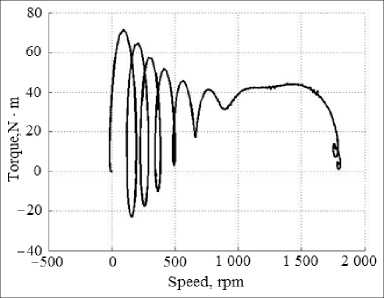
F i g. 2. Torque ‒ speed (ideal AM model)
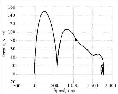
F i g. 3. Torque ‒ speed (modified AM model)
The torque form of the modified AM model (fig. 3) was larger and more stable during the machine acceleration compared with the model of idealized AM (fig. 2). In the graph of fig. 2, during the machine acceleration a braking and acceleration loops were observed, which could be difficult to explain with any some physical processes in AM, but which have observed with all idealized AM model in modeling.
In the graph of fig. 3, the start-up process corresponded to real processes. Comparison of graphs have showed the utility of accounting for the design of windings in the AM model.
The refinement of the AM model was achieved thanks to the application of the method of calculating magnetic fluxes for electric machines – the RVMF method.
Discussion and Conclusions
To calculate the absolute values of the magnetic fluxes of an electric machine, many methods have been developed that at the same time have weakly reflected the type of AM windings, have little affect the model of the machine27–33 [9–14]. The RMMF method, in contrast to other methods, provided a refinement of the AM model according to the type of its windings by means of correction functions34 [5–7; 11].
The need to refine the AM model using the deviation of the distribution of magnetic induction in the air gap AM from the sinusoidal form existed for a long time [4; 8; 15–16]. This has confirmed by the experience of using the method of harmonic analysis. The task to refine the AM model become obvious after the appearance of various variants of AM vector control velocity where the idealized model AM35–40 was used [4; 8]. However, a deeper and more dynamic AM control required a more accurate AM model [4–7; 8; 11; 15–16]. The RMMF method has specifically designed to calculate the correction functions and correction factors for the idealized AM model in order to obtain a model of real AM [5–7; 11].
Distinctive features of the RMMF method:
‒ calculation of the distribution of magnetic induction in the air gap along the teeth contours;
‒ determination of the magnetic flux of the single-turn of tooth contour as a unit of magnetic flux;
‒ calculation of the relative values of the magnetic fluxes of the windings with this new unit of magnetic flux;
‒ the use of the movable measuring winding, similar in design to the phase winding of the stator, as the image of any of windings of machine;
‒ application of correction functions for multiplication by elements of inductance matrices in the idealized AM model in order to obtain the model of real AM.
The correction functions (functions of the electric angle of displacement of the rotor windings relative to the stator windings) turned out to be suitable for clarifying the Clark and Park transformations [5; 7; 11]. The Clark and Park transformations were one of the foundations for all building systems of vector control of AM. Therefore, the correction functions could be applied in existing vector control systems (without the alteration of these control systems)41 [11].
Simulation in MATLAB showed that the refinement of the AM model according to the winding design has made electromechanical processes more similar to real processes [7; 11].
These results made it possible to create a method for controlling the rotation speed of a three-phase machine41. National Research Mordovia State University became the patent owner of this method of controlling electrical machines. The patent was tested for novelty in major countries.
Of course, even the most advanced calculations and simulations unable to replace the electric drive tests with a real mechanism. However, the improvement of the model serves to improve the asynchronous electric drive.
Useful properties of the method of relative magnitudes of magnetic fluxes ‒ RMMF allow us to hope for its successful use for other types of electrical machines.
Submitted 21.11.2017; revised 28.12.2017; published online 20.03.2018
The author has read and approved the final version of the manuscript.
References Method of relative magnitudes for calculating magnetic fluxes in electrical machine
- Blondel A. Notes sur la theorie elementaire des appareils a champ tournant. La Lumiere Electrique. 1893; 50:605-616. (In French)
- Park R. Two reaction theory of synchronous machines. Transactions AIEE. 1929; 48:716-730. Available at: http://ieeexplore.ieee.org/document/5055275
- Gorev A. A. . Trudy Leningrad-skogo politekhnicheskogo instituta = Works of Leningrad Politechnical Institute. 1936; 5:32-19. (In Russ.)
- Ansari A. A., Deshpande D. M. Mathematical model of asynchronous machine in MATLAB Simu-link. International Journal of Engineering Science and Technology. 2010; 2(5):1260-1267.
- Zakharzhevskii O. A., Panfilov S. A. Display of the structure of windings in the model of the asynchronous machine. Collected Scientific Papers SWorld. 2013; 8(2):36-39.
- Zakharzhevskii O. A., Afonin V. V. Simulation of acceleration asinchronous machine. Collected Scientific Papers SWorld. 2013; 7(4):9-13.
- Zakharzhevskii O. A., Afonin V. V. . Elektronnoye modelirovaniye = Electronic Modeling. 2014; 36(4):101-116. Available at: http://dspace.nbuv.gov.ua/handle/123456789/101017 (In Russ.)
- Luo X., Liao Y., Toliyat H. A., Lipo T. A. Multiple coupled circuit modeling of induction machines. IEEE Transactions Industrial Applications. 1995; 31(2):311-317.
- Akbari H., Meshgin-Kelk H., Milimonfared J. Extension of winding function theory for radial and axial nonuniform air-gap in salient pole synchronous machines. Progress in Electromagnetics Research. 2011; 114:407-428. Available at: http://www.jpier.org/PIER/pier114/25.11011201.pdf
- Qi L., Fan T., Wen X. Armature-reaction magnetic field analysis for interior permanent magnet motor based on winding function theory. IEEE Transactions on Magnetics. 2013; 49(3):1193-1201 DOI: 10.1109/TMAG.2012.2224358
- Zakharzhevskii O. A., Afonin V. V. Patent RU. No. 2557071, IPC H02P 21/00 of 25.02.2013. The Method of vector control of speed of three-phase machine. Patentee: Mordovia State University. (In Russ.) Mechanical engineering 75 ВЕСТНИК МОРДОВСКОГО УНИВЕРСИТЕТА Том 28, № 1. 2018
- Zakharzhevskii O. A., Afonin V. V. . Vestnik Yuzhno-Uralskogo gosudarstvennogo universiteta. Seriya: Energetika = Bulletin of South Ural State University. Series Power Engineering. 2015; 15(4):74-82 (In Russ.)
- Lubin T., Hamiti T., Razik H., Rezzoug A. Comparison between finite-element analysis and winding function theory for inductances and torque calculation of a synchronous reluctance machine. IEEE Transactions on Magnetics. 2007; 43(8):3406-3410 DOI: 10.1109/TMAG.2007.900404
- Tessarolo A. Accurate computation of multiphase synchronous machine inductances based on winding function theory. IEEE Transactions on Energy Conversion. 2012; 27(4):895-904. DOI: 10.1109/TEC.2012.2219050
- Kyung-Tae K., Jun-Kyu P., Jin H., Byeong-Woo K. Comparison of the fault characteristics of IPM-type and SPM-type BLDC motors under inter-turn fault conditions using winding function theory. IEEE Transactions on Industry Applications. 2014; 50(2):986-994 DOI: 10.1109/TIA.2013.2272911
- Bossio G., Angelo C. D., Solsona J., Garcia G., Valla M. I. A 2-D model of the induction machine: An extension of the modified winding function approach. IEEE Transactions on Energy Conversion. 2004: 19(1):144-150.
- Serrano-Iribarnegaray L., Cruz-Romero P., Gomez-Exposito A. Critical review of the modified winding function theory. Progress in Electromagnetics Research. 2013; 133:515-534.
