Methods for assessing the state of snow-ice cover

Author: Mashkov Viktor G., Malyshev Vladimir A., Fedyunin Pavel A.
Journal: Журнал Сибирского федерального университета. Серия: Техника и технологии @technologies-sfu
Article in issue: 3 т.14, 2021.
Free access
The development new methods for measuring the electrophysical and geometric parameters multilayer dielectric medium in order to identify their layers, as well as to detect inhomogeneities in them, is an urgent scientific task. Methods for assessing the state the snow-ice cover are proposed, based on the identification layers of the snow-ice cover by the dielectric permittivity obtained indirectly as a result inclined sounding of the underlying surface by an electromagnetic wave with vertical and horizontal polarization. Under normal sensing the underlying surface, in the form snow-ice cover, by radio waves with vertical and horizontal polarization, the obtained values the reflection coefficient from the boundary layers the received signals are identical. Oblique sensing by a vertically polarized wave in the range from 25 to 90 degrees leads to a sharp dip in the values the reflection coefficient from the boundary layers at certain angles, so for dry snow - 47…55°, dry firn - 55 … 58° and dry ice - 58…61°. These angles characterize the dielectric properties the layers (permittivity), which are explained by the complete polarization the reflected wave in a plane perpendicular to the plane incidence, since at this moment the vibrations the layer's electrons along the direction their movement do not lead to the emission electromagnetic waves in the direction the reflected wave (absent). The given estimated values the complex relative permittivity snow-ice cover as two component medium air and ice at a temperature from minus one to minus forty degrees, or three component medium air, ice and water at zero temperature are a sample for establishing the identity the characteristic properties layers. The purpose this article is to develop methods for assessing the state snow-ice cover used in determining the possibility performing a safe landing a helicopter - type aircraft on an unprepared site with snow-ice cover based on the identification the obtained characteristics snow-ice cover layers based on the results radar sensing with calculated data.
State snow-ice cover, underlying surface, permittivity, layer identification, oblique sensing
Short address: https://sciup.org/146282224
IDR: 146282224 | UDC: 621.317.335.3:551.578.465 | DOI: 10.17516/1999-494X-0312
Методы оценки состояния снежно-ледяного покрова
Предложены методы оценки состояния снежно-ледяного покрова, основанные на идентификации слоев снежно-ледяного покрова по диэлектрической проницаемости, полученной косвенным путем в результате наклонного зондирования подстилающей поверхности электромагнитной волной с вертикальной и горизонтальной поляризацией. При нормальном зондировании подстилающей поверхности в виде снежно-ледяного покрова радиоволнами с вертикальной и горизонтальной поляризацией полученные значения коэффициента отражения от границ раздела слоев принятых сигналов идентичны. Наклонное зондирование вертикально поляризованной волной в пределах от 25 до 90° приводит к резкому провалу значений коэффициента отражения от границ раздела слоев при определенных углах: так, для сухого снега - 47…55°, сухого фирна - 55…58° и сухого льда - 58…61°. Эти углы характеризуют диэлектрические свойства слоев (диэлектрическую проницаемость), объясняемые полной поляризацией отраженной волны в плоскости, перпендикулярной плоскости падения, поскольку в этот момент колебания электронов слоя вдоль направления своего движения не приводят к излучению электромагнитных волн в направлении отраженной волны (отсутствует). Приведенные оценочные значения комплексной относительной диэлектрической проницаемости снежно-ледяного покрова как двухкомпонентной среды воздуха и льда при температуре от минус 1 до минус 40° либо трехкомпонентной среды воздуха, льда и воды при нулевой температуре являются образцом для установления тождественности характеризующих свойств слоев.Цель данной статьи - разработка методов оценки состояния снежно-ледяного покрова, используемых в определении возможности выполнения безопасной посадки воздушного судна вертолетного типа на неподготовленную площадку со снежно-ледяным покровом, на основе идентификации полученных характеристик слоев снежно-ледяного покрова по результатам радиолокационного зондирования с расчетными данными.
Text of the scientific article Methods for assessing the state of snow-ice cover
Цитирование: Машков, В. Г. Методы оценки состояния снежно-ледяного покрова / В. Г. Машков, В. А. Малышев, П. А. Федюнин // Журн. Сиб. федер. ун-та. Техника и технологии, 2021, 14(3). С. 316–331. DOI: 10.17516/1999–494X-0312
in making a decision to land a HTA on an unprepared (unequipped) snow-ice platform. Landing on the snow-covered pond with snow depth above the permissible or thickness the ice cover below the permissible in accordance with the type HTA, may lead to breaking through the snow, ice, or roll HTA day and night in simple and adverse weather conditions (fog, haze, rain, snow, dust, or smoke the atmosphere), and also in conditions raised snow rotating propeller [1, 2].
Method for estimating the state snow-ice cover by Brewster angle
Identification snow-ice cover layers. Measurement complex relative permittivity materials with losses in the microwave range [3–5], based on measuring the dependence the coefficient of Fresnel reflection a flat sample the material from the angle incidence within the range θ = 40°…90° when the electric field the wave parallel to the plane incidence, then the graph the dependence the coefficient of Fresnel reflection from the angle incidence determine the Brewster angle θ B and the relative complex dielectric permittivity ε the sample material or portion the surface the earth is calculated by the formula ε = (tg θ B )2.
Since the snow-ice cover is a multi-layer structure with different densities, water content shares, and its own structures, it is important to determine the boundaries the a ir– s now, s now– i ce, and i ce– w ater layers. It is not always possible to obtain peaks echo signals from the boundary s now- i ce layers as a result the contrast the complex relative permittivity the layers, since if the snow is inhomogeneous, compacting to the bottom so that at the s–i boundary ε s ≈ ε i , then there is no reflection from the s–i boundary at all [6]. But, as a rule, the snow cover has layers with various complex relative permittivity, increasing in depth, which is due to their compaction during snowfall, thawing, cooling, etc., which allows you to receive echoes from the boundary layers snow-ice cover. Moreover, for example, for freshwater ice (at λ = 3 cm), the amplitude the echo signal from the i–w border will be greater than from the s–i border, this is observed when the thickness the ice cover is less than 1.6 m [6].
On the territory the Russian Federation, the thickness the ice cover on rivers and lakes varies from 0.1 m in the southern regions to 3 m in the polar zone Siberia and up to 4 m on the ice sections rivers in Eastern Siberia. In most cases, and especially in highly salty sea ice, the thickness does not exceed 2 m [6].
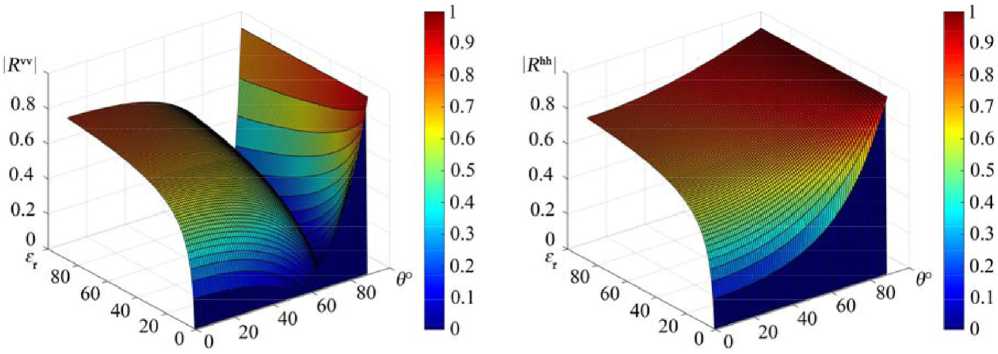
The dependence the reflection coefficient of the Fresnel with vertical polarization R vv on the complex relative permittivity the medium ε r and the sensing angle within the limits θ = 40°…90° has a pronounced dip in values (Fig. 1a) compared to the dependence the reflection coefficient of the Fresnel with horizontal polarization R hh (Fig. 1b). For vertical and horizontal polarization (vv, hh – the first index the probing, the second received radio signal).
The reflection coefficient from the boundary snow-ice layers is determined by [4, 7] the sensing angle and the relative permittivity the corresponding layer:
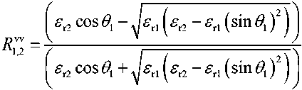
, where θ 1 – sensing angle;
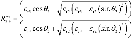
, where 6, = arcsin
(sin eJ^Z) ;
a) b)
Fig. 1. Dependence the Fresnel reflection coefficient: a – with vertical polarization R vv; b – with horizontal polarization R hh on the complex relative permittivity the medium and the sensing angle within θ = 0°…90°
, where 9; = arcsin
^(sin^/^) .
The total reflection coefficient (1) from the snow-ice cover without taking into account multiple reflections between the layer boundaries is determined by the recurrent formula [4]:
^w(hh) _
^w(hh)
+ C^ exP (-^W^7^7)
1 , ovv(hh) nw(hh) 1 I ^S . 1 j4l1 1,-
ехр(-74^+1/л7^7)
where hri+1 – is the depth (i + 1)-layer; λ – is the wavelength the probing signal; ^w(hh) _ Q , k ≠ i, k ≠ i + 1. The speed propagation an electromagnetic wave (EW) in a snow-ice cover is lower than the speed propagation in the air, depending on its density, water content, and structure. For dry snow Vds = 278,1…212,7 m/μs, dry firn Vdf = 212,7…189,0 m/μs and dry ice Vdi = 189,0…167,9 m/μs, vary very markedly depending on the proportion water content, since for pure water Vpw = 32,74…41,97 m/μs, the preferred orientation and shape ice and air inclusions in snow [2], so it is necessary to take into account the wavelength in the layer.
Given the change in the wavelength in the layers, in formula (2) we obtain: уууууму. _ УУУТ^УУ „w уууутуиу.
V l+^^exptr,,)’ 1,4 l+^^exp^)' 24 И-^^ир^)'
^"-(hh) + 1 ^vvthh) ^wthb) / \ where
relative depth
( i + 1)-layer's; A,+i=^=– wavelength in the layer.
It is known that if the probing signal falls on the boundary two dielectrics at an angle θ 1 equal to the Brewster angle θ B , then the reflected θ' 1 and refracted θ 2 signals are perpendicular to θ' 1 + θ 2 = 90°.
– 319 –
In this case, the reflected signal will be completely polarized in the plane perpendicular to the plane incidence (absent), and the degree polarization the refracted beam will be maximum. According to Snellius law (3), for a wave with the angle incidence θ 1 and the angle θ 2 refraction at the boundary two dielectrics, the equality is valid for the medium under study (with μ = 1: snow, firn, ice):
SH!^) _П^ _ _^e2
, where n2, n1 – is the refractive index the first and second layers the medium; n2,1 – the refractive index the boundary the first and second layers; ε1 and ε2 – the relative permittivity the first and second layers, respectively.
The Brewster angle is defined:
6B = arctg( //2,) = arctg Л^- . ‘ UM
The Brewster angle for the i -th layer boundary, at which there is no reflected signal with vertical polarization from the i -th layer boundary, will be determined
θB 1, i+1 = arctg(ni+1,1), where ni+1,1 = ni+1 / n1 – the refractive index the i-th layer boundary, then
6B L /+1 = arctg f—1 = arctg | ^M ] , (4)
the sensing angle the first layer the underlying surface θ B 1, i +1 ≠ θ B 1, k . The refractive i -th layer boundary increases in depth with increasing snow cover density.
According to the proposed method, probing the radio signal with vertical polarization the controlled area the snow-ice cover within the limits θ = 40°…90°, allows us to determine the dependence the Fresnel reflection coefficients -^,7+1, ( i , i + 1)-boundary layers on the angle incidence the radio wave.
Fig. 2 shows the Fresnel reflection coefficients ^■7+i for layers with complex relative permittivity: ε r2 = 1,3 – j0,0008, ε r3 = 1,8 – j0,0008, ε r4 = 2,3 – j0,0008, ε r5 = 2,8 – j0,0008, ε r6 = 3,1 – j0,0008, ε r7 = 74 – j, depending on the sensing angle within θ = 40°…90°. The increase in electrical conductivity for seawater ( ε r7 = 74 – j) is due to the presence salinity S sw = 35 g/kg.
A sequential increase in the sensing angle, starting from θ = 40°, will lead to a sequential decrease (disappearance) each subsequent peak the echo signal from the subsequent layer boundary at the appropriate θ , since the density the snow-ice cover increases as the depth increases, ranging from ρ r = 10 kg/m 3 – for freshly fallen snow to ρ r = 917 kg/m 3 – for dry ice without air inclusions.
Thus, the intervals the snow-ice cover densities will correspond to the intervals of Brewster angles. So for dry snow ρ ds = 100…500 kg/m 3 ( ε ' ds = 1,162…1,984) – θ Bds = 47°…55°, dry firn ρ df = 500…700 kg/m 3 ( ε ' df = 1,984…2,51) – θ Bdf = 55°…58°, dry ice ρ di = 700…917 kg/m 3 ( ε ' di = 2,51…3,179) – θ Bdi = 58°…61°. As the moisture content increases, the values of Brewster angles shift to the values for water. For sea water ε ' sw = 74 salinity is S sw = 35 g/kg, and for pure (meltwater) water ε ' pw = 87 with – θ Bsw = 84°.
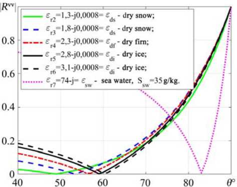
Fig. 2. Fresnel reflection coefficients R i v , i v + 1 for layers with complex relative permittivity: ε r2 = 1,3 – j0,0008, ε r3 = 1,8 – j0,0008, ε r4 = 2,3 – j0,0008, ε r5 = 2,8 – j0,0008, ε r6 = 3,1 – j0,0008, ε r7 = 74 – j depending on the sensing angle within θ = 40°…90°
The graphs (Fig. 2) show the absence reflected signals from the boundary layers at θ , for medium with complex relative permittivity: ε r2 = 1,3 – j0,0008, ε r3 = 1,8 – j0,0008, ε r4 = 2,3 – j0,0008, ε r5 = 2,8 – j0,0008, ε r6 = 3,1 – j0,0008, ε r7 = 74 – j depending on the sensing angle within the range θ = 40°…90°, respectively, equal to the Brewster angles θ B i , i +1: θ B1,2 = 49°, θ B2,3 = 53°, θ B3,4 = 57°, θ B4,5 = 59°, θ B5,6 = 60°, θ B6,7 = 83°.
The solution the inverse problem the reconstruction the layers. The essence solving the inverse problem estimating the dielectric permittivity individual layers snow-ice cover based on the determination of Brewster angles is as follows. Let the object sensing the underlying surface is a snowice cover of k layers irradiated by a linear frequency modulated (LFM) signal at an angle of 40 to 90 degrees by an electromagnetic wave with vertical polarization.
Brewster angles are determined using the minimum measured Fresnel reflection coefficient for i , i + 1 the boundary between layers snow and ice cover θ B i , i +1 . At the same time, the Brewster angles θ B i , i +1 are determined sequentially, which allows us to determine the permittivity each subsequent layer from the formula (4):
ε r i +1 = (tg θ B1, i +1)2. (5)
The methodological error in determining the dielectric permittivity layers (Fig. 2) at Brewster angles θ B i , i +1 at specified design values ε r i +1 (for example, obtained θ B1,2 = 49°, θ B2,3 = 53°, θ B3,4 = 57°, θ B4,5 = 59°, θ B5,6 = 60°, θ B6,7 = 83°) constructed according to formula (1) and determined according to formula (5), that is, their assessment without taking into account the impact of noise is no more than 3 %, which indicates the validity using formula (5).
To estimate errors in measuring the permittivity layers corresponding to the actual practical situation, an additive Gaussian noise was added to the values of Brewster angles θ B i , i +1
θBi,i+1exp = θBi,i+1 + n(f), where n(fξ) – is the noise affecting ξ measurement, due to both the error the measurement complex and other experimental errors during the experiment, and the reliability the selected electrodynamic model the real physical situation.
With this in mind, formula (5) will take the form
ε r i +1exp = (tg θ B1, i +1 )2 + n ( f ).
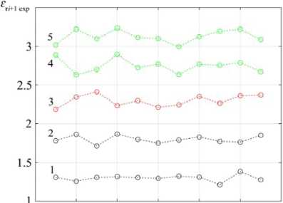
Fig. 3 shows the dependence the measured values the relative permittivity ε r i +1exp the k layers (Fig. 3a) and the error their estimation (Fig. 3b) when the values RMS the noise level increase from 3.8 to 4.8 in increments of 0.1 for 100 implementations each, where 1 – ε r2exp, 2 – ε r3exp, 3 – ε r4exp, 4 – ε r5exp, 5 – ε r6exp .
The analysis dependencies in Fig. 3 shows that the value errors in estimating the measured values the relative permittivity ε r i +1exp of k layers when the values RMS the noise level increase from 3.8 to 4.8 in increments of 0.1 for 100 implementations each with a confidence probability of 0.95 does not exceed 10 %, which indicates the validity using this method.
The obtained values permittivity layers ε r i +1 ( i + 1)-layers are identified with the sample values dielectric permeability layers ε vrΔ and the estimated state the snow-ice condition ε r i +1 = ε vrΔ : ''snow cover'', ''firn'', ''ice cover'' or ''water''.
At negative temperatures T = –1…–40 °C, the real part the complex relative permittivity layers ε' r ( ε' s – snow, ε' f – firn, ε' i – ice) with the density layers ρ r = 100…917 kg/m3 ( ρ r = 100…500 kg/m3; ρ f = 500…700 kg/m3; ρ i = 700…917 kg/m3) do not depend on f = 1…10 GHz, but only on T in small limits. The real part the sample values relative permittivity wet medium ε' vrΔ (for the General formula a three-component medium): ε' vsΔ – snow; ε' vfΔ – firn; ε' viΔ – ice; ε' pwΔ – pure water; ε' swΔ – sea water.
For example, T = –1…–40 °C for snow, as a two-component medium air and ice, the actual part the permittivity ε' vsΔ is between air ε' vaΔ = 1 and ice ε' viΔ = 3,15 (for dry dense ice without air inclusions with ρ i = 917 kg/m3 – ε' viΔ = 3,20±0,02), for firn (densely Packed, granular and partially recrystallized, usually multi-year snow, i. e. an intermediate stage between snow and glacier ice), the relative permittivity approaches the values for ice. For water under a snow-ice cover at T = 0 °C frequencies f = 2…8 GHz,
3.8 3.9 4.0 4.1 4.2 4.3 4.4 4.5 4.6 4.7 4.8 a
a)
3.8 3.9 4.0 4.1 4.2 4.3 4.4 4.5 4.6 4.7 4.8 a
b)
Fig. 3. Dependence: a – measured values the relative permittivity ε r i +1exp of k layers; b – errors in their estimation when the values RMS the noise level increase from 3.8 to 4.8 in increments of 0.1 for 100 implementations each
there is a smooth decrease in the actual part the dielectric constant for meltwater ε' pwΔ = 83,84…51,03, for sea water with a salinity of S sw = 35 g/kg – ε' swΔ = 74,97…48,42 determined by the Debaev model [2].
The values the real part the dielectric constant the medium is calculated using the formula Of G. Lueng [2, 10–12] for such medium with spherical air and ice inclusions
^ ^(^(V?"^1) , (6)
where v i = ρ r / ρ i – the volume content ice; ρ r – the density the d ry medium ( d ry s now ρ ds , d ry f irn ρ df , d ry i ce ρ di ); ρ i = 917 kg/m3 – the density dry ice without air inclusions; ε' i – the actual part the dielectric permittivity ice.
At temperature T = 0 °C, a significant contribution to the permittivity will be made by humidity (the proportion water content in the layer) for a two-component ice-water mixture with water-filled pores t^^+^^-i/?)) , (7)
where P w – is the total percentage water content; ε' i and ε' w – the relative permittivity ice and water, respectively. General formula for a three-component medium [2, 10–12] consisting ice with water and air inclusions including special cases (6) and (7)
<=(< о - p.. vp.,^+p«-p. )) , (8)
where P wa – is the total percentage water and air content.
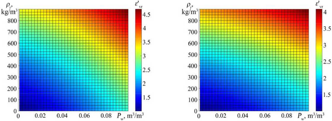
Fig. 4 shows the dependence the real part the complex relative permittivity the medium (snow, firn, ice) on the density the medium ρ r (6) and the proportion water content (7) P w = 0…0,1 for f = 2 GHz (Fig. 4a), for f = 8 GHz (Fig. 4b) when T r = 0 °C.
Thus, based on the dielectric constant obtained indirectly as a result inclined sensing the underlying EW surface with vertical polarization, it is possible to restore the parameters the layers snow-ice cover (density ρ r , percentage water content P w ).
a) b)
Fig. 4. Dependence the real part the complex relative permittivity the medium ε ' vr (snow, firn, ice) on the density the medium ρ r (6) and the proportion water content P w = 0…0,1 (7) for: a – f = 2 GHz; b – f = 8 GHz when T r = 0 °C
The depth snow-ice cover layers is measured as follows.
The geometrical parameters the layers the snow-ice cover. Probing a controlled section snowice cover with a linear frequency modulated (LFM) signal [6, 13] that implements the frequency principle determining the depth layers snow-ice cover, based on the selection the beat frequency (difference signal) obtained by multiplying the received and probing (reference) signals.
Generated in the transmitting device LFM signal with frequency ftx(t) = f0 + αtm, ∀ 0 < tm < Tm, (9)
where f = 2 GHz – is the starting frequency, α = 600 GHz/s – the rate change frequency (LFM slope), tm – the time within a single period modulation chirp signal (fast time), a Tm = 10 ms – the period modulation (chirp LFM signal) and receiving echo signals by a receiver with a frequency frx(t) = f0 + α(tm – τ), ∀ τ < tm < Tm, (10)
collected according to the classical scheme. At the same time, it is necessary to note the requirement for the formation a LFM signal in the transmitting device: a constant signal amplitude at the output and a high linearity the frequency-time dependence.
The received echo signal from the boundary snow-ice layers at a distance r has a time delay τ defined by the expression
τ = 2 r / V r i , (11)
where V r i – is the speed propagation the EW in the i -layer [2].
The frequency component the beat f b is directly related to the delay the echo signal (11), which is the difference between the expressions (9) and (10)
f b = f tx – f rx = ατ = 2 rB / V r i T m , (12)
where B – the spectral width (deviation) LFM signal.
The depth the snow-ice layers is determined by the resulting distance difference from formula (12), which pass the probing signals according to the formula r = fb Vri Tm / 2B under normal probing to the underlying surface.
The total time delay, without taking into account the multi-layer snow-ice cover, τ d to the boundary the ''ice cover – water'' τ iw medium is generally defined
2А 2А 2Л
Ta = T- = Г „ + Г + Г, =--- +--- H--L
, c ys where τas – time delay to the boundary the ''air – snow cover'' environment; τs, τi – time delay in snow and ice cover, respectively; ha – distance from AHT to the ''air – snow'' medium boundary; hs – snow depth; hi – the depth the ice cover; Vs, Vi – the speed propagation electromagnetic effects in the snow and ice, respectively.
To improve the accuracy measuring the depth snow and thickness ice cover, when restoring the structure the underlying surface, it is necessary to take into account the propagation velocity EW [2] to each layer the medium (11).
The signal delay to the ''snow cover – ice cover'' medium boundary is determined τ is = τ as + τ s .
The resolution the depth the FM–CW radar, when using an ultra-wide-band LFM signal that overlaps the C…S (3.75…15 cm) bands, with a frequency from 2 GHz to 8 GHz ( B = 6 GHz) is about 4 cm [1, 2, 13], which is a good indicator when determining the possibility performing a safe landing a helicopter-type aircraft on an unprepared area with snow and ice cover.
Thus, the probability identifying the components the structure the snow-ice cover increases, thereby increasing the level safety landing a helicopter – type aircraft on an unprepared site with snow-ice cover, transporting (delivering) cargo and objects along a reservoir with snow-ice cover, by increasing the depth resolution, which when using an ultra-wide-band LFM signal with a frequency from 2 GHz to 8 GHz ( B = 6 GHz) is about 4 cm. In this case, the error in determining the permittivity the layers (Fig. 2) at Brewster angles θ B i , i +1 at the specified calculated values ε r i +1 and according to the formula ε r i +1 = (tg θ B i , i +1 )2 in other words the methodological error is no more than 3 %. The value the error in estimating the measured values the relative permittivity ε r i +1exp the k layers when the values the noise level RMS increase σ from 3.8 to 4.8 in increments of 0.1 for 100 implementations each with a confidence probability of 0.95 does not exceed 10 %, which indicates the validity using this method.
Method for remote identification the state snow-ice cover by the ratio of Fresnel reflection coefficients
Identification snow-ice cover layers. In [14] based on the radiation controlled area the sea surface microwave radio waves on an inclined polarization in the interval of θ = 25°…75°, registering the scattered back signal, defined Bragg mechanism scattering, both on the vertical and horizontal polarizations, calculate the polarization ratio normalized backscattering cross sections measured at vertical σ vv0 and horizontal σ hh0 polarizations and calculated relative permittivity the medium below the boundary the atmosphere-ocean.
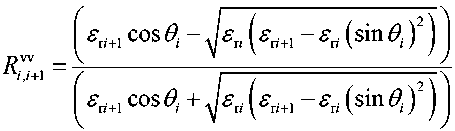
The total coefficient reflection the Fresnel from the snow and ice cover without taking into account multiple reflections between the layer boundaries during oblique sounding by flat microwave radio waves with vertical and horizontal polarization is determined by the recurrent formula [4, 15] (2).
For horizontal polarization (hh – the first index the probing, second received radio signal) [15]:
| ^" cos 6*, - J(^+i - 5 (sin ^ ) )
^ = . (13)
I ^" COS 0; + £j+1 - £•, (sin 61, ) )
The dependence the reflection coefficient the Fresnel with vertical polarization R vv calculated by the formula (1) on the complex relative permittivity the medium ε r and the sensing angle within the limits θ = 0°…90° has a pronounced dip in values (Fig. 1a), called the Brewster angle, compared with the dependence the reflection coefficient the Fresnel with horizontal polarization R hh calculated by the formula (13) (Fig. 1b).
When restoring the structure, the snow-ice cover according to this method, the EW [2, 11] propagation velocity is taken into account in the same way as the above method for estimating the state of the snow-ice cover by the Brewster angle.
The power the reflected signal from the snow and ice cover is determined by the formula [13]:
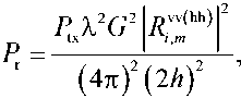
where P tx – power the transmitting device; λ – wavelength; G – antenna gain; h – height in HTA.
On both polarizations, the radio signal (14) at a particular time has the same parameters P tx , λ, G , h and since this dependence is leveled when calculating the ratio the Fresnel reflection coefficients vertically and horizontally polarized signals, the ratio will be determined by three parameters: ε r m , θ and f tx . Expression (14) does not take into account the roughness layers snow-ice cover, since the radio wave is not mirrored, but is scattered at different angles, but when calculating the ratio, the Fresnel reflection coefficients vertically and horizontally polarized signals, this dependence is also leveled.
According to the proposed method, probing the radio signal simultaneously with vertical and horizontal polarization the controlled area the snow-ice cover within the limits θ = 25°…45°, allows us to determine the dependence the reflection coefficients the Fresnel with vertical and horizontal ^+i polarization, ( i , i + 1)-boundary layers on angle incidence radio wave.
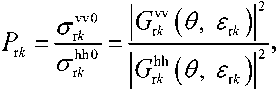
Relative permittivity snow-ice layers is determined from the ratio of Fresnel reflection coefficients by power P r m (Fig. 5) signals with |^| vertical (Fig. 1a) obtained by formulas (1), (13) and |с|2 horizontal (Fig. 1b) obtained by formulas (1), (13) polarizations:
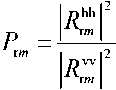
where 1^™ I , 1^™ I – the reflection coefficients of the Fresnel on power (reflectivity) measured on the horizontal (hh and vertical (vv) polarizations, respectively (the first index is the polarization the probing, the second – the received radio signal); m – the number peaks the echo signal (the boundaries the layers snow-ice cover with different relative permittivity).
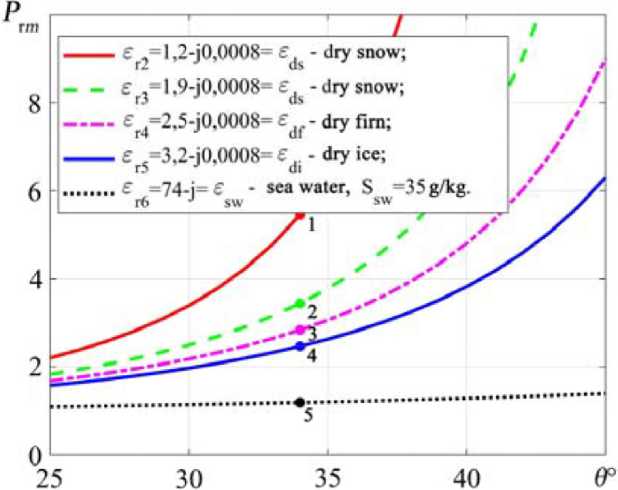
Fig. 5. Ratios of Fresnel reflection coefficients by power P r m signals with vertical obtained by formulas (2), (4) and horizontal obtained by formulas (3), (4) polarizations: 1 – ε r2 = 1,2 – j0,0008, 2 – ε r3 = 1,9 – j0,0008, 3 – ε r4 = 2,5 – j0,0008, 4 – ε r6 = 3,2 – j0,0008, 5 – ε r7 = 74 – j, depending on the sensing angle within θ = 25°…45°
The maximum angle oblique sensing θ = 25°…45° the controlled section snow-ice cover is determined by the lower Brewster angle θ = 46° for the layer snow-ice cover with the lowest relative permittivity d ry s now – ε rds = 1,07 – j0,0008.
Fig. 5 shows the ratio of Fresnel reflection coefficients by power P r m for layers with complex relative permittivity: 1 – ε r2 = 1,2 – j0,0008, 2 – ε r3 = 1,9 – j0,0008, 3 – ε r4 = 2,5 – j0,0008, 4 – ε r6 = 3,2 – j0,0008, 5 – ε r7 = 74 – j, depending on the sensing angle within θ = 25°…45°.
Successive determination the permittivity each subsequent layer up to ε r m , where m = 1… n – is the number layers snow-ice cover, is carried out by the formula:
1 + 47^W ^(^ tan(y)2 , (i-7^))
which corresponds to the graphs in Fig. 5 the dependency (15).
The interval snow-ice cover densities will correspond to the intervals the Fresnel reflection coefficient ratios by power P r m . For example, when θ = 46° for dry snow ρ ds = 100…500 kg/m3 ( ε' ds = 1,162…1,984) – P r m = 5,6915…3,3266, dry firn ρ df = 500…700 kg/m3 ( ε' df = 1,984…2,51) – P r m = 3,3255…2,8311, dry ice ρ di = 700…917 kg/m3 ( ε' di = 2,51…3,179) – P r m = 2,8311…2,4753. With an increase in the moisture content the values the Fresnel reflection coefficient ratios by power P r m decrease, aiming for values for water. For sea water ε' sw = 74 ( s ea w ater) salinity S sw = 35 g/kg this P r m = 1,1923, a for p ure (thawed) water with ε' pw = 87 – P r m = 1,1760.
To identify the layers snow-ice cover, the identity the obtained values the dielectric permittivity the layers ε r m with the specified calculated (model) values of the dielectric permittivity the layers ε vrΔ is established by the condition ε r m = ε vrΔ : ''snow cover'', ''firn'', ''ice cover'' or ''water'' similar to the above method.
Thus, the methodological error in determining the dielectric permittivity layers (Fig. 5) based on the ratios Fresnel reflection coefficients P r m for the given values ε r m and according to formula (16) is no more than 1,5 %, which indicates the validity of using this method.
Method for remote determination the state snow-ice cover by backscattering polarization relations
Identification snow-ice cover layers. The normalized cross section the backscattering σ vv(hh)0 in the case propagation the resonant components the wave field over a flat surface can be represented by the formula [14]:
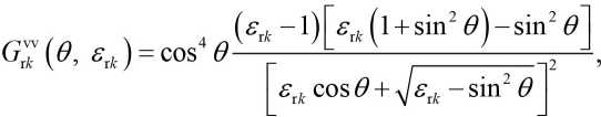
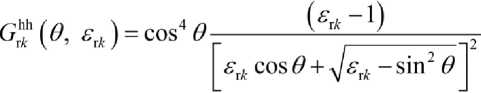
(V,^=s^|G"<->(e,^
where vv(hh) – vertical and horizontal polarization, the first index corresponds to the polarization the radiated signal, the second taken; k r k – wave number radio waves; E(^) – the range snow, ice or water surface, according to the relevant wave vector K^Tk the resonant components.
On both polarizations, a signal with the same wave net k r k is proportional to the roughness the snow, ice, and water surface, respectively, and since this dependence is leveled when calculating the polarization ratio vertically and horizontally polarized signals, the polarization ratio will be determined by three parameters: ε r k , θ , and f . Knowing the polarization relations of the signals P r k , the sensing angle θ , and the frequency f , iteratively determine the permittivity each subsequent layer ε r k +1 .
The relative permittivity of snow-ice layers is determined from the polarization relations backscattering P r k (Fig. 6) signals with vertical СГд (Fig. 7a) and horizontal °"rT (Fig. 7b) polarizations:
where сг^ , °"Т – normalized cross section backscattering measured on the vertical (vv) and horizontal (hh) polarizations, respectively (the first index is the polarization the probing signal, the second – the received signal); k – the number peaks of the echo signal (the boundary between layers of snow-ice cover with different permittivity, corresponding to the number of layers of snow-ice cover); 1бЖ 64 , ^(е, =Д – geometric coefficients that depend on the type polarization, the angle incidence radio waves at the boundary layers, and the electrophysical (dielectric permittivity) parameters layers snowice cover a reservoir [16],
θ = 25°…75° – the angle sensing the controlled area the snow-ice cover the reservoir determined by the resonant (Bragg) scattering mechanism.
From the formulas (17)–(19), the complex relative permittivity snow-ice layers is determined:
The interval snow-ice cover densities will correspond to the intervals polarizing relations P r k backscattering signals. So for example, when θ = 65° for dry snow ρ ds = 100…500 kg/m3
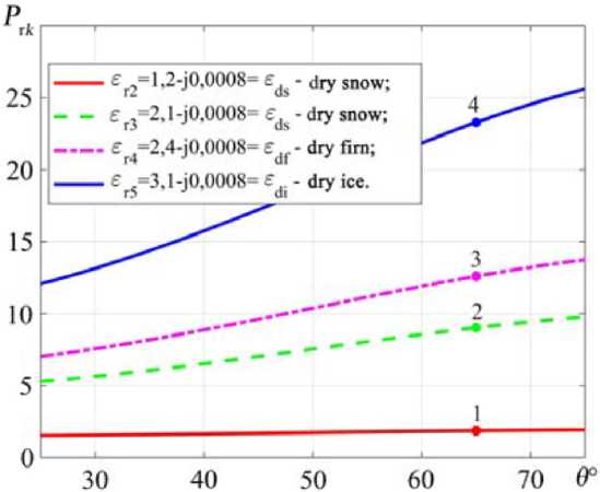
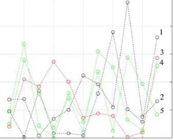
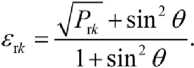
Fig. 6. Polarization relations P r k backscattering signals with vertical σ vv0, obtained by formulas (17), (18) and horizontal σ hh0, obtained by formulas (17), (19) polarizations: 1 – P r2 = 1,8613, 2 – P r3 = 9,0212, 3 – P r4 = 12,6012, 4 – P r5 = 23,2799, depending on the sensing angle within θ = 25°…75°
a)
b)
Fig. 7. Dependence the normalized cross-section backscattering: a – with vertical polarization σ vv0; b – with horizontal polarization σ hh0 on the complex relative permittivity the medium ε r and the sensing angle within θ = 0°…90°
( ε' ds = 1,162…1,984) – P r k = 1,6772…7,7967, for dry firn ρ df = 500…700 kg/m3 ( ε' df = 1,984…2,51) – P r k = 7,7967…14,0648, for dry ice ρ dш = 700…917 kg/m3 ( ε' di = 2,51…3,179) – P r k = 14,0648…24,6891. As the moisture content increases значения, the values the polarization ratios P r k the backscattering signals increase significantly, tending to the values for water. For sea water ε' sw = 74 ( s ea w ater) salinity is S sw = 35 g/kg this P r k = 17949, а for pure (meltwater) water with ε' pw = 87 – P rk = 24854.
The obtained values of the dielectric permittivity the layers ε r k are compared with the calculated (model) values the dielectric permittivity the layers ε vrΔ . By establishing the identity which condition ε r k = ε vrΔ determines the state the snow-ice cover the reservoir: ''snow cover'', ''firn'', ''ice cover'' or ''water''.
Methodological error in determining the permittivity of layers (Fig. 6) based on the polarization relations P r k the normalized cross-sections backscattering °"r7° , at the specified values ε r k and according to the formula (20) is no more 1 %, which indicates the legality using this method.
Conclusion
Thus, the probability of correct identification of the constituent elements of the snow and ice cover structure increases, thereby increasing the level of safety of landing a helicopter-type aircraft on an unprepared site with snow and ice cover, by increasing the depth resolution, which when using ultra-wideband LFM signal with a frequency from 2 GHz to 8 GHz ( B = 6 GHz) is about 4 cm.
The error in determining the dielectric permittivity layers (Fig. 2) at Brewster angles θ B i , i +1 for the specified calculated values ε r i +1 and according to formula (5), i. e. the methodological error is no more than 3 %. The value of the error in estimating the measured values of the relative permittivity of ε r i +1exp k layers with increasing values of the RMS noise level σ from 3.8 to 4.8 in increments of 0.1 for 100 implementations of each with a confidence probability of 0.95 does not exceed 10 %.
Thus, the methodological error in determining the dielectric permittivity layers (Fig. 5) based on the ratios Fresnel reflection coefficients P r m for the given values ε r m and according to formula (16) is no more than 1,5 %.
Methodological error in determining the permittivity of layers (Fig. 6) based on the polarization relations P r k the normalized cross-sections backscattering °"r7° , at the specified values ε r k and according to the formula (20) is no more 1 %.
The results obtained allow us to draw a conclusion about the applicability the proposed methods for assessing the state snow-ice cover used in determining the possibility performing a safe landing a helicopter-type aircraft on an unprepared site with snow-ice cover based on the identification the obtained characteristics snow-ice cover layers based on the results radar sensing with calculated data.
References Methods for assessing the state of snow-ice cover
- Mashkov V. G., Malyshev V. A. Sposob vibora ploshadki dly posadki vozdushnogo sudna vertoletnogo tipa [Method for selecting a landing site for a helicopter-type aircraft]. Patent RF, no. 2707275 G01S 13/94. Publ. 26.11.2019. (In Russ.)
- Mashkov V. G., Malyshev V. A., Prohorskiy R. A. Sposob ocenki vozmozhnosti posadki vozdushnogo sudna vertoletnogo tipa na vodoem so snezhno-ledyanym pokrovom [Method for assessing the possibility of landing a helicopter-type aircraft on a body of water with snow and ice cover] Patent RF, no. 2737761 G01S 13/94. Publ. 02.12.2020. (In Russ.)
- Finkel'shtejn M. I., Lazarev E. I., CHizhov A. N. Radiolo-kacionnye aeroledomernye s'emki rek, ozer, vodohranilishch. L., Gidrometeoizdat, 1984, 112 p. (In Russ.)
- Kanarejkin D. B., Pavlov N. F., Potekhin V. A. Poly-arizaciya radiolokacionnyh signalov. Ed. V. E. Dulevicha. M., Sov. radio, 1966, 440 p. (In Russ.)
- Mashkov V. G., Malyshev V. A. Model helicopter-type aircraft landing control on an unprepared snow-covered area. Modeling, optimization and information technology. 2019, no. 4 (27), pp. 1-10. doi: 10.26102/23106018/2019.27.4.037 (In Russ.)
- Malyshev V. A., Mashkov V. G. The speed electromagnetic wave propagation in the snow-ice underlying surface. Radioengineering. 2020, vol. 84, no. 3 (5), pp. 4054. doi: 10.18127/j00338486-202003(05)-05 (In Russ.)
- Mashkov V. G., Malyshev V. A. Model for controlling the landing of a helicopter-type aircraft on a reservoir with snow and ice cover. Modelirovanie, optimizaciya i in-formacionnye tekhnologii [Modeling, optimization and information technology]. 2020, no. 3 (30), pp. 1-9. doi: 10.26102/2310-6018/2020.30.3.017 (In Russ.)
- Shoshin E. L., Suchanek A. M., Plyusnin I. I. Sposob izmereniya tolshchiny snezhnogo pokrova [The method of measuring the snow cover thickness]. Patent RF, no. 2262718. Publ. 20.10.2005. (In Russ.)
- Shostak A. S., Zagoskin V. V., Lukyanov S. P., Karaush A. S. O vozmozhnosti opredeleniya dielektricheskoj pronicaemosti verhnih sloev podstilayushchih sred po izme-rennym koefficientam otrazheniya pri naklonnom zondi-rovanii ploskimi volnami vertikal'noj i gorizontal'noj poly-arizacii v SVCH diapazone // ZHurnal radioelektroniki [Radio electronics magazine]. 1999, no. 11. Available at: http://jre.cplire.ru/mac/nov99/4/abstract.html (date accessed 07.12.2017) (In Russ.)
- Valeev G. G. Sposob izmereniya otnositel'noj kom-pleksnoj dielektricheskoj pronicaemosti materiala s po-teryami v SVCH diapazone [Method for measuring the relative complex permittivity of a material with losses in the microwave range]. Patent RF, no. 2613810. Publ. 21.03.2017. (In Russ.)
- Zapevalov A. S. Sposob distancionnogo opredeleniya otnositel'noj dielektricheskoj pronicaemosti sredy pod granicej atmosfera-okean [Method for remote determination of the relative permittivity the medium under the atmosphere-ocean boundary]. Patent RF, no. 2623668. Publ. 28.06.2017. (In Russ.)
- Kotlyakov V. M., Macheret Yu. Ya., Sosnovsky A. V., Gla-zovsky A. F. Speed of radio waves propagation in dry and wet snow cover. Led i sneg [Ice and Snow]. 2017, no. 57, iss. 1, pp. 45-56. doi: 10.15356/2076-6734-2017-1 -45-56 (In Russ.)
- Sudarsan Krishnan B. E. Modeling and simulation analysis of an FMCW radar for measuring snow thickness. Electronics and communication engineering. University of Madras, 2000, 84 p.
- Kupryashkin I. F., Likhachev, V. P., Rya-zantsev L. B. Malogabaritnye mnogofunkcional'nye RLS s nepreryvnym chastotno-modulirovannym izlucheniem [Small-sized multifunctional radars with continuous frequency-modulated radiation]. M., Radiotekhnika, 2020, 288 p. doi: 10.18127/B9785931081915 (In Russ.)
- Grinev A. Yu., Temchenko V. S., Bagno D. V. Radary podpoverhnostnogo zondirovaniya. Monitoring i diagnostika sred i ob'ektov [Subsurface sensing radars. Monitoring and diagnostics among objects]. M., Radiotekhnika, 2013, 392 p. (In Russ.)
- Macheret Yu. Ya. Estimation of water content in glaciers by hyperbolic reflections. Materialy glyaciolog-icheskih issledovanij [Materials of glaciological research]. 2000, no. 89, pp. 3-10. (In Russ.)
- Glazovsky A. F., Macheret Y. Ya. Voda v lednikah. Metody i rezul'taty geofizicheskih i distancionnyh issledovanij. [Water in glaciers. Methods and results of geophysical and remote sensing studies]. M., GEOS, 2014, 528 p. (In Russ.)
- Macheret Yu. Ya., Glazovsky A. F. Estimation of absolute water content in Spitsbergen glaciers from radar sounding data. Polar Research. 2000, vol. 19, iss. 2, pp. 205-216. doi: 10.3402/polar.v19i2.6546
- Macheret Yu. Ya. Radiozondirovanie lednikov. [Radioecho sounding of glaciers]. RAN, Institute of geography. M., Scientific World, 2006, 389 p. (In Russ.)
