Microcontroller-Based Automobile Tracking System with Audio Surveillance using GPS and GSM Module
Author: Nureni A. Yekini., Adetokunbo O. Oloyede, Akinwole K. Agnes, Folasade M.Okikiola
Journal: International Journal of Information Engineering and Electronic Business(IJIEEB) @ijieeb
Article in issue: 3 vol.8, 2016.
Free access
This paper presents automobile tracking system with audio surveillance using GPS and GSM Module to provide an alternative solution to security challenges experienced by car owner, and to develop a system that can track the location of vehicles. We make use of Microcontroller Unit, GPS, and GSM unit. The design is an embedded application, which will continuously monitor a moving Vehicle and report the status of the Vehicle on demand. The PIC18F452 microcontroller is interfaced serially to a GSM Modem and GPS Receiver. A GSM modem is used to send the position (Latitude and Longitude) of the vehicle from a remote place. The GPS modem will continuously give the information indicating the position of the vehicle. The GPS modem gives many parameters as the output, but only the data coming out is read and sent to the user's phone number. We use RS-232 protocol for serial communication between the modems and the microcontroller. A serial driver IC is used for converting TTL voltage levels to RS-232 voltage levels. When the request by user is sent to the number in the modem, the system automatically sends a return reply to the mobile phone indicating the position of the vehicle in terms of latitude and longitude from this information we can track our vehicles.
Automobile tracking system, PIC18F452 microcontroller, GSM Modem, GPS Receiver, RS-232 protocol
Short address: https://sciup.org/15013421
IDR: 15013421
Text of the scientific article Microcontroller-Based Automobile Tracking System with Audio Surveillance using GPS and GSM Module
Published Online May 2016 in MECS
The drastic increase in the number of vehicles theft brings about the need to secure the vehicle as an advancement in the usefulness of technology to man. Vehicle tracking with audio surveillance using GSM and GPS module is about tracking the position of the vehicle and monitoring the audio activities going on in the vehicle using GPS and GSM module. Modern vehicle tracking systems commonly use GPS or GLONASS technology for locating the vehicle, but other types of automatic vehicle location technology can also be used [1]. Vehicle information can be viewed on electronic maps via the Internet or specialized software. Tracking system is very important in modern world which can be useful in monitoring, tracking of the theft vehicle and various other applications [2, 3]. Methods of audio surveillance are variations of three basic forms. First, both in frequency of use and in volume of take obtained, is the telephone tap; second comes the concealed microphone connected by wires with a recorder; and third, the micro phonic pick-up of a concealed wireless transmitter in circuit with a monitoring receiver [4]. Most of today’s vehicle tracking system uses Global Positioning System (GPS) to get an accurate reading of the vehicle position. The popularity of surveillance systems for tracking and monitoring humans and vehicles using video information is expanding rapidly in contemporary times. Advances in computing power, increased safety concerns, increased global threats and a greater awareness and search in developing countries and organization security capabilities have all contributed to this realization. Vehicle tracking systems in particular are finding improved use in a range of intelligent transportation systems and applications [5], including measuring traffic flow parameters, detecting accidents [6, 7], autonomous guided vehicles, and for surveillance monitoring in security applications.
In this research work, we present a microcontrollerbased global automobile tracking system. The system is made up of a GPS and GSM. It uses only one GPS device and a two way communication process with a GSM module. The system will be installed on a vehicle so that it could be track by its owner or a third-party for its position. Communication components such as cellular (GSM) and satellite transmitter will be combined to transmit the vehicle’s position to remote user. Vehicle’s information can be viewed by using software on a computer.
-
A. Aims and Objectives
The aim of this research work is to design and implement a vehicle tracking system using micro- controller with GPS and GSM module. If the system is design and implemented the following objectives can be achieve.
The objective of this project is to achieve a design of such system that can provide the following.
-
■ Obtain Information of the vehicle position every time there's a request for it.
-
■ Ensures safety and security of vehicle by tracking its position.
-
■ Capturing the audio conversation in the vehicle at all points.
-
■ Research output will provided a wide range of security to ensure that any cases of stolen vehicle can be fast tracked, and monitored for the safety and recovery of the vehicle, aided by the device tracker using the GSM as a link.
-
II. Tools and Methodology
This device is made up of the following major units, namely; Microcontroller Unit, GPS, GSM unit, and Power Supply Stage. The units are interface as shown in the system block diagram and data flow in figure 1 below.
The design is an embedded application, which will continuously monitor a moving Vehicle and report the status of the Vehicle on demand. The PIC18F452 microcontroller is interfaced serially to a GSM Modem and GPS Receiver. A GSM modem is used to send the position (Latitude and Longitude) of the vehicle from a remote place. The GPS modem will continuously give the information indicating the position of the vehicle. The GPS modem gives many parameters as the output, but only the data coming out is read and sent to the user’s phone number. We use RS-232 protocol for serial communication between the modems and the microcontroller. A serial driver IC is used for converting TTL voltage levels to RS-232 voltage levels. When the request by user is sent to the number in the modem, the system automatically sends a return reply to the mobile phone indicating the position of the vehicle in terms of latitude and longitude from this information we can track our vehicles.
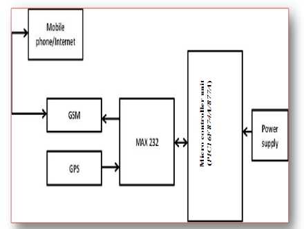
Fig.1. System Block Diagram and Data Flow
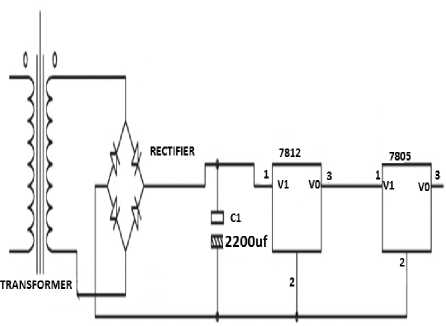
Fig.2. Power Supply Unit
The power supply stage is a linear power supply type that made up a step down transformer, filter capacitor, and voltage regulators, to give the various voltage levels. After stepping down to 12volts and filtering with a 2200uf capacitor to remove ripples, the voltage is regulated to 12volts and 5volts respectively. See figure 2.
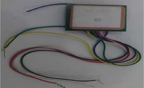
Fig.3. System GPS Unit
The Global Positioning System (GPS) is a space-based global navigation satellite system (GNSS) that provides reliable location and time information in all weather and at all times and anywhere on or near the Earth when and where there is an unobstructed line of sight to four or more GPS satellites. Figure 3 is the diagram of GPS unit used in this research work. GSM unit is of a SIM 900 GSM module interfaced to the microcontroller with a communication cable. This device is selected due to its support for AT command. The source code programmed in the Microcontroller consist of a set of AT command used to instruct the phone (GSM) to send a predetermined message to a phone number or push a call to a user of based on the request of the user. Every communication between the MCU and this device is done with the help of the AT command. This GSM unit has a slot for the installation of a SIM card as shown in the front view of figure 4, when a message is sent to the SIM card installed in the module; the module sends an interrupt vector through its Tx line to the MCU, consequently the MCU request for the received message for processing. Figure 5 shows the back view of the GSM module.
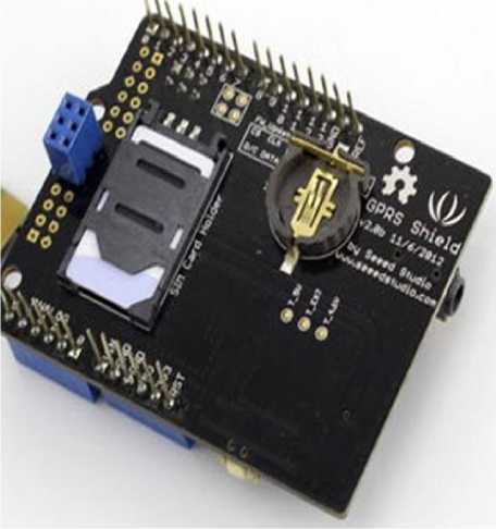
Fig.4. GSM Module front View Indicating SIM Card Slot
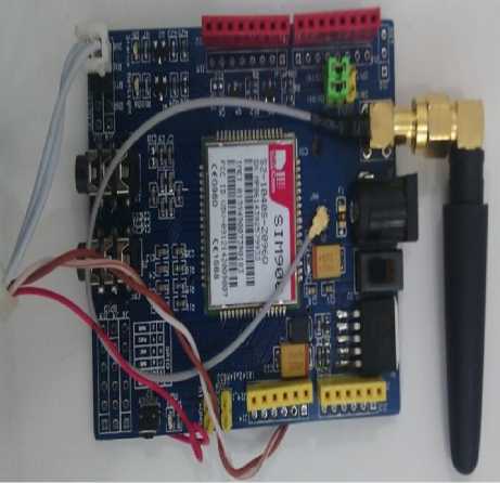
Fig.5. Back View of the GSM Module
The MCU is being powered with a 5v Dc supply; it operates with a crystal 0f 20 MHz and two 33pf stability capacitor. The GSM Module is connected to the Tx (pin 25) and Rx (pin 26) Pin of the MCU for serial communication, same as the GPS module. When the MCU set into operation, it runs through the code for the initialization of the necessary operations like enabling of the interrupt initialization, sending of the initialization code to the GSM module. After the initialization process the Microcontroller operation code is written such as to respond to a valid message received by the GSM module with the help of an interrupt vector from the Tx line of the GSM module, then the MCU sends a command to the GPS module to receive the location and it transfers it to the GSM Module before its being sent to the user. See figure 6 for the PIN layout of the MCU ( PIC16F874A/877A ) used in this research work.
40-Pin PDIF
MCLR/Vpp - RAO/ANO ■ RA1/AN1 -RA2/AN2/VREF-/CVREF . RA3/AN3/Vref+ .
RA4/T0CKI/C1OUT -RA5/AN4/SS/C2OUT -RE0/RD/AN5 -RE1/WR/AN6 -RE2/CS/AN7 - Vdd- VSS-OSC1/CLKI -OSC2/CLKO -
RC0/T1OSO/T1CKI ■ RC1/T1OSI/CCP2 -RC2/CCP1 -RC3/SCK/SCL -RDO/PSPO « RD1/PSP1 -
C 10
C 13
C 15
E 16
C 18
E 19
E 20

40 □
RB7/PGD
39 □ -— RB6/PGC
38 □
RB5
37| □ -—- RB4
36 ZJ
RB3/PGM
35 □ —* RB2
34 □
33 □
32 □
RB1 RBO/INT
Vdd
30 Ц - -29 □ - * 28 □ ——
27 Zl-^— 26 3 *—•
25 □—— 24 Z| —
23 Zl^^ 22 □ —-
21 Z|^^
RD7/PSP7 RD6/PSP6 RD5/PSP5 RD4/PSP4 RC7/RX/DT RC6/TX/CK RC5/SDO RC4/SDI/SDA RD3/PSP3
RD2/PSP2
Fig.6. PIC16F874A/877A MCU
-
III. Implementation and Testing
-
A. Implementation
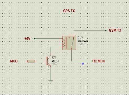
Figure 8, gives the schematic diagram of the project on proteus, when the device is powered on, the indicator led is switched on by the MCU, and a delay of about 27secs is observed for the GSM module to initialize and register the network. A code is written for the MCU to wait on a valid SMS (GET) message through the GSM module, when the message is received, the MCU is notified through a USART (Universal Synchronous Asynchronous Receiver and Transmitter) interrupt, the MCU then carries out an arithmetic operation to confirm if the message is valid, if it is not a valid message, the MCU will discard the message and do nothing. But if the received message is valid (i.e the message is GET), the MCU will switch control to the GPS module to receive the Longitude and latitude coordinates. When the Longitude and latitude coordinates are received, the code written takes care of separating the essential data and adding a link to the coordinates, and then the MCU sends a message back to the user who requested for the location of the device. The message sent out to the user through the GSM module consists of the device location on the satellite. All the user need do is to click on the received message on an internet enabled phone and the goggle map browser will be link automatically indicating the location of the device through its position on the map. After the message sent, the device also initiates a call to the mobile number through which it received a request.
During implementation, this device will be connected to the car and kept in a save location away from the eyes of all. The device will be powered by the car battery, and also a backup battery will be provided, in case the car battery is disconnected. Also the SIM card in the device can be recharged remotely by the user from anywhere.
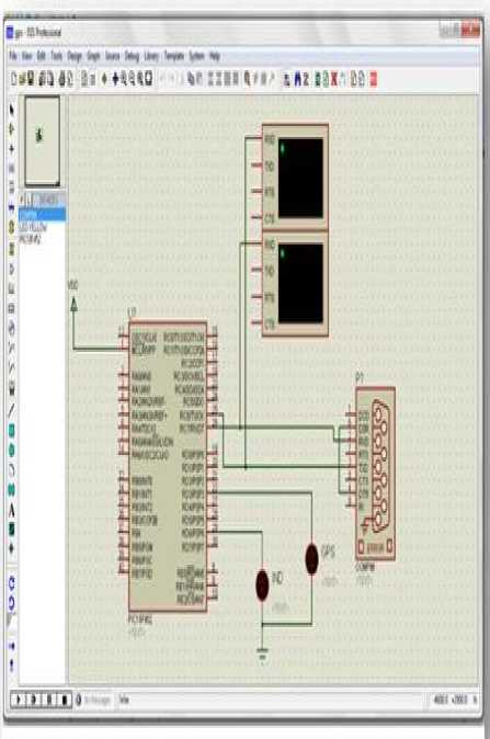
Fig.8. Schematic Diagram of the Project on Proteus
Figure 9 show the integration of circuitry for the system.
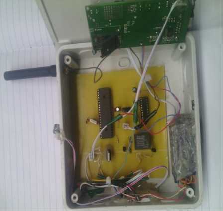
Fig.9. Circuit Integration of the Proposed System
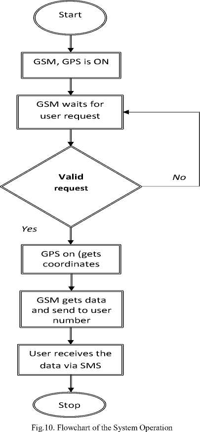
The flowchart in figure 10, illustrate the basic operation of the system.
-
B. Testing
In testing and debugging, a request by the user via a text message containing the word “GET” to the number at the modem, the system automatically sends a reply in this format “ com/maps?q=*.*******+*. *******” to that mobile indicates the position of the vehicle in terms of latitude and longitude. From this information we can track our vehicles. The system is powered on by the red switch button, after which the red GSM module light comes up as illustrated in figure 1. The light stay on for a while and goes off immediately it receives a network but if it doesn’t receive the network, the light stays on. After the GSM module light is off i.e. it has received network, a “GET” message is sent to the SIM number in the GSM module which in turn reply with the coordinate of the location stating its longitude and latitude as shown in figure 13, after retrieving it from the GPS module. The GPS module thus flashes its blue light while retrieving the coordinates from the satellite as shown in figure 12. When the coordinate sent by the GSM module is followed, it referred to the google map showing the location of the vehicle being tracked and the exact position it is as shown in figure 14 below.
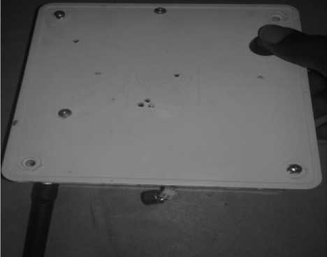
Fig.11. Proposed System after Switching ON

Oloyede and Yekini Tracker
maps?q = 7.OT 75+22.855
+1M’M 06:07
GET
06: r a
Oloyede and Yekini Tracker maps?g=6.71 90+23.1 02
■Mituue ое-io
; -- [Type text message
Fig.13. Coordinate Sent by GSM module
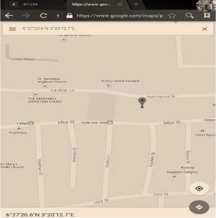
Fig.14. Vehicle Location on Google Map
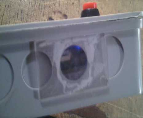
Fig.12. GPS Module Flashing Blue Light while Retrieving the Coordinate
-
IV. Conclusion
Vehicle Tracking System with audio surveillance using GPS and GSM presents efficient location of the vehicle on the map by integrating the several communication technologies and display setups. The locations of the vehicle are displayed on Google map, GPS and GSM modems are used to track the location of the information and to send the information to tracking server.
References Microcontroller-Based Automobile Tracking System with Audio Surveillance using GPS and GSM Module
- Vlcek, Charles, Patricia McLain, and Michael Murphy. "GPS/Dead Reckoning for Vehicle Tracking in the 'Urban Canyon' Environment". IEEE Vehicle Navigation & Information Systems Conference, Ottawa-VNIS'93.
- Jianyang Zheng, Yinhai Wang and Nancy L. Nihan (2008). "Tracking Vehicles with GPS". Seattle, Washington.
- Zografos, K.G.and K.N. Androutsopoulos. "Assessing The Impacts From The Introduction of Advanced Transport Telematics Technologies In Hazardous Materials Fleet Management". National Research Council U S Transportation Research Board 80th Annual Meeting, 2001.
- Telit Wireless Solutions (2007) GM862-GPS Hardware user guide. 1vv0300728 Rev. 8, 20/09/07 World Academy of Science, Engineering and Technology 37 2010
- K. Jien, T. Watanabe, S. Joga, L. Ying, and H. Hase. An hmm/mrf-based stochastic framework for robust vehicle tracking. IEEE Transactions on Intelligent Transportation Systems, 5(3):142–154, September 2004.
- S. Kamijyo, Y. Matsushita, and M. Sakauchi. Traffic monitoring and accident detection at intersections. IEEE Transactions on Intelligent Transportation Systems, 1:108–119, June 2000.
- L. Zhu, J. Song, Q. Huang, M. Zhang, and H. Liu. A novel module of tracking vehicles with occlusion. In Proceedings of the IEEE Intelligent Vehicles Symposium, pages 894–899, June 2005.
