Modal regulators of a direct current electric drive with a pulse-width converter

Author: Pakhomov A.N., Krivenkov M.V., Ivanchura V.I.
Journal: Сибирский аэрокосмический журнал @vestnik-sibsau
Section: Математика, механика, информатика
Article in issue: 7 (33), 2010.
Free access
The technique of modal regulators synthesis of instantaneous coordinates values of direct current digital electric drives with a pulse-width converter by a state space method taking into account the influence of variable pure delay in the control channel is presented.
Modal regulator, direct current electric drive, pulse-width converter
Short address: https://sciup.org/148176419
IDR: 148176419
Text of the scientific article Modal regulators of a direct current electric drive with a pulse-width converter
The theory of digital repeated systems of the subordinated regulation of the electric drive [1–3] is developed well enough. Less attention has been paid to electric drive systems constructed on the basis of summation of feedbacks on a state vector that allows to expect the decrease of sensitivity to variations of control object parameters. In domestic literature such regulators are usually called modal because factors of a feedback vector directly influence eigenvalues (modes) of the closed system matrix. In the present paper the task of designing of such regulators is set. The task includes:
-
– reception of discrete equations of a control object condition according to its differential equations;
-
– definition of feedback factors by state variables according to the set spectrum of a matrix of the closed digital control system dynamics;
– introducing the corrective amendments connected with some features of the real pulse-width converter (PWC). It is supposed that the influence of variable pure delay in the control channel of a double digital system which is rather typical for an electric drive system with microprocessor control is taken into account.
The reasons of occurrence of two periods of discreteness as well as the nature of pure delay in microprocessor systems are considered in works [4; 5]. It is supposed that the interruption period (IP) of work of a control microcomputer contains integer N of the switching periods (SP) PWC: T = NTk, where T and Tk are values IP and SP accordingly. In view of two periods of discreteness it is expedient to introduce two types of relative time – global τ and local one inside IP θ, whereby t t N
τ= Tt ; θ= Tt = TNt = N τ ; θ ∈ [0, N ]. (1)
Below only thus determined relative values of time are used. Let the calculation of a control signal u [ n ] on IP with number n is completed after computing delay τ d on k of the SP (fig. 1). Local computing delay θ d is counted off from the beginning of SP with number k . If the local time delay θ PWC1 necessary for realization of u [ n ] is more than θ d (fig. 1) then this realization can be carried out already on k of the SP. The previous value of a control signal u [ n– 1] is realized o n the first k of the SP.
Fig. 1
If 6 PWC2 < 6 d (fig. 1) then the realization of u [ n ] is postponed up to SP with number k + 1. In that specific case when k = N – 1 it will begin only from the SP with number zero on n + 1 of the IP.
The delay of 6 PWC is caused by the nature of semiconductor PWC the outpot voltage of which is adjusted due to the change of its size.
In a local time scale the size of pure delay belongs to the range: 0 < 6A< N + 1 [5]. Therefore it is convenient to break it into whole K and fractional 5 parts: 6A = K + 5 .
Digital regulators designing includes calculation of discrete state equations parameters of a control object in view of the influence of pure delay having a general view according to [4; 5]:
X [ n + 1] = Ф IP X [ n ] + W IP u [ n ], (2)
where the vector of state variables, transitive and weight matrices for IP will be written down as:
|
X [ n ] = |
■ X [ n ] " _ ^ t[ n ] j |
% ; Ф1Р = |
■ Ф 1р (1) F" _ 0 0 _ |
; |
|
|
w W IP |
= |
■ H 1 |
; ,У 1 [ n + 1] = u [ n ]. |
(3) |
|
In matrices (3) an additional variable of a condition y 1 is introduced for the case when the whole part of pure delay on a global scale to time is equal to one IP.
If regulation is carried out according to instant values of coordinates then the calculation of matrices F and H is carried out according to formulas [4]:
F = Ф . K(1){Osp(1)...{Osp(1) + E}+... + E}^sp(1 -5); 144424443 14243
K - 1 K - 1
H = { Ф sp (1). . . { Ф sp (1) + E } + ... + E } ^ sp (1 -5 ),. (5)
144424443 14243
N - K - 1 N - K - 1
where ФSP and W SP are transitive and weight matrices for SP, E is an individual matrix.
The synthesis of a digital modal state regulator by the set spectrum of a matrix of dynamics is possible in the only case when [6] the pair of matrices [ФIP , W IP ] is completely controlled. Let P be a vector of feedback factors of dimension l , where l is the amount of state variables (the order of a characteristic polynomial of a system). Value P can be found from [6]:
P = [( GS T ) - 1( Y" g )] t , (6)
where
W ф W ф2 w ф п 1v ■
W IP ф1Р W IP ф1Р W IP ф1Р w IP J ;
y = [ y i - i y i - 2 L Y o ] T ; g = [ g i - i g i - 2 L g о ] T ;
|
■ g i |
0 |
0 |
|
|
g l - 1 |
gl |
0 |
|
|
G = |
g i - 2 |
g i - 1 |
gl |
g1g2g3L gl where y и g are factors of a characteristic polynomial of a closed system and a control object.
If factor gi * 0 then triangular matrix G is not degenerate [6]. Therefore, for the existence of vector P the matrix of controllability S should have a rank l , or, which is the same, the pair of matrices [ФIP , W IP ] should be controlled.
In a real system with the PWC the size of pure delay is variable and it is necessary to take into account this fact while synthesizing the regulators of digital systems. Let us consider the synthesis of a modal regulator and the research of a closed digital system of a direct current electric drive with the PWC. In view of variable character of pure delay A some values of feedback factors corresponding to the range of changes A of the latter are counted. Intermediate values are derived by interpolation.
The system of continuous differential equations for the SP does not depend on the model of a power converter and looks like [3]:
di d 9 d ю d e
"6?
1 i .
6 m
--OH--u, e e aa
where i , ю are relative values of armature current and frequency of an engine shaft rotation accordingly; 6 a и 6 m are relative electromagnetic and electromechanical constants of time. Let, for example, 6 a = 8, 6 m = 32 и N = 4 then matrices of dynamics and an input of continuous equations of condition (7) are equal:
" 0.125 " 0.125 0.125
, B =
0.03125 0 0
Factors P ( A ) in the model are set as the table of conformity between size A and eigenvalues of feedback factors which should be calculated prior to the beginning of modelling. The values of vector P are calculated for a linear model with an ideal pulse element in the assumption of the steady-state mode. A part which realizes variable factor P ( A ) carries out linear interpolation between two values nearest to it if size A does not coincide with the calculated values. It allows to reduce the number of elements of the table of conformity because calculations show that the curve of dependence of factors values P ( A ) is monotonous and smooth enough .
In table the values of feedback factors in a direct current electric drive system with PWC calculated according to the technique described above for a number of values A are shown. Here P I is a vector of feedback factors on an instant armature current, P ю is a vector of feedback factors on instant frequency of rotation of an engine shaft, PU is a vector of feedback factors on the value of a control signal on previous IP which is an additional state variable.
A binomial spectrum of a matrix of a closed system dynamics with an equivalent constant of time тю describing its speed and equal to 1,5 was chosen as an example for calculation of values of factors P ( A ).
Factors of feedback
|
Δ |
0 |
0,2 |
0,25 – |
0,25 + |
0,45 |
0,65 |
0,85 |
1,05 |
1,25 - |
|
P I |
1,1103 |
1,0963 |
1,0926 |
0,5029 |
0,4912 |
0,4795 |
0,4677 |
0,456 |
0,4442 |
|
P ω |
3,9081 |
3,7977 |
3,7704 |
1,5461 |
1,4964 |
1,4478 |
1,4004 |
1,3543 |
1,3093 |
|
P U |
0 |
0 |
0 |
–0,223 |
–0,16 |
–0,099 |
–0,04 |
–0,017 |
–0,017 |
One can see in the table that if the size of pure delay is greater than the SP of the PWC then there is an additional feedback [4] – nonzero factor P U in the model. At the same time the presence of a feedback on one more coordinate of a system can appear to be useful from the point of view of increase of roughness of an electric drive system.
Let’s consider the calculation of transients in the described system by means of a package of imitating modelling Matlab of the firm The MathWorks , Inc . The corresponding structure of a closed system for modelling in a tool Simulink of package Matlab is shown in fig. 2.
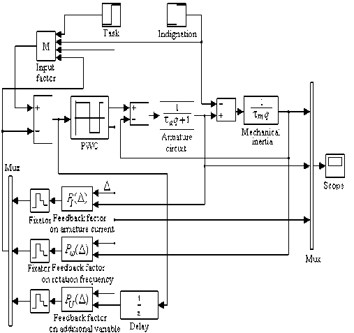
Fig. 2
The block diagram of a model will consist of connected in series model PWC and parts of a control object of a direct current electric drive system, where q is a dimensionless Laplace operator. The variable factors of feedback dependent on value Δ given out by the PWC which are switched N times for IP are included in models. Relative constants of time τ a и τ m are N times less than θ a and θ m [4].
To correct the static mistake caused by the application of a load moment an adjustable input factor M was introduced into the structure. Its size depends, apart from everything else, on the value of a load moment. As it is known, the measurement of the latter is inconvenient, therefore below a variant of absence of such dependence is considered. An input factor is calculated according to the formula:
M = 1 +
xl⋅ pl ∑∗ lx where l is the amount of state variables, xl is an instant value of l-variable at the end of IP, pl is the value of a feedback factor on l-variable, x∗ is the sum of values of master control and a reference signal.
It should be noted that an input factor for a reference signal which was introduced to provide a zero static mistake depends on the size of pure delay as the factors of a characteristic polynomial of a closed system transfer function will change together with the change of vector P .
The size of a delay θ PWC represents the factor of PWC filling β which is calculated according to the formula [3]: ∗
ω +i +1
β= 2f , where ω∗ is a preset value of an engine speed, if is the static current accepted as a disturbing signal for a system.
In fig. 3 one can see the curves of transients of the described system which have a typical for a binomial spectrum aperiodic character and a preset speed. Along the horizontal axis there are values of global relative time. The presence of pulsations can be explained by a pulse character of armature current. Disturbance compensation provides a zero static mistake. The size of computing delay introduced by a microcomputer is equal to 0.1. The maximal control signal and EMF of a voltage source of the PWC are both equal to 1. The signal of the task is a jump from a level of 0.1 up to 0.2 with displacement on three IP (for clearness). A static current step from 0.05 up to 0.1 is displaced on 25 IP to provide the established mode in a system after performing the task.
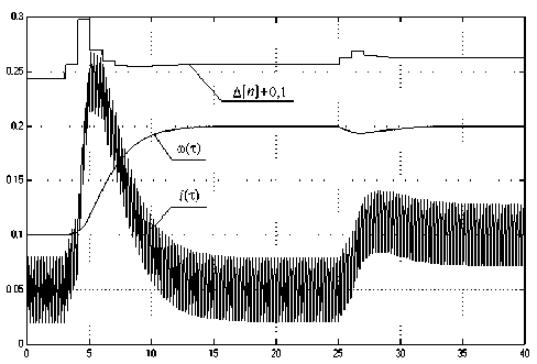
Fig. 3
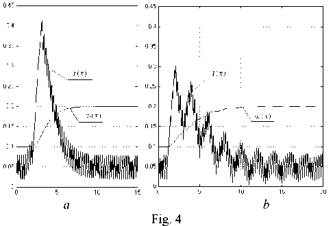
As it has already been mentioned the actual size of pure delay can vary rather widely and under its significant deviation from the calculated value transients can be completely unacceptable. The developed technique of modal regulators synthesis allows to exclude subharmonic oscillations typical for high-speed systems with a part of pure delay in the control channel. Subharmonic oscillations are oscillations the period of which exceeds the IP by an integer of times [3]. Fig. 4 shows schedules of processes in a digital electric drive system for two cases:
– feedbacks with variable factors in the function of pure delay (fig. 4, a );
– feedbacks with constant factors calculated in the assumption of an average value of pure delay equal to one IP [3] (fig. 4, b ). It is obvious, that in the second case in the process of performing the task there appear converging subharmonic oscillations as a result of which the speed of a system decreases approximately in one and a half time. If the speed of a system increases considerably subharmonic oscillations can even increase. In any case their occurrence is extremely undesirable, as they are badly filtered by flyweights because of their low frequency and it leads to additional losses of energy.
Conclusions:
– the analysis of time delays introduced by a microcomputer together with the PWC is made and the principle of their account is established in the process of calculation of the discrete state equations of a control object;
– the technique of numerical calculation of modal state regulators is developed in view of the influence of variable pure delay in a microprocessor system with several periods of discreteness;
– the account of variable character of pure delay allows to remove subharmonic oscillations typical for high-speed closed digital systems;
– there is an opportunity to decrease a static mistake (to its full compensation) and to reduce a dynamic mistake significantly if disturbing influence in a system can be supervised and measured.
