Model and simulation of proton exchange membrane fuel cell performance at different porosity of diffusion layer

Author: Yongsheng Wei, Hong Zhu
Journal: International Journal of Modern Education and Computer Science (IJMECS) @ijmecs
Article in issue: 2 vol.3, 2011.
Free access
The proton exchange membrane fuel cell is an example of clean energy. Recently, a three-dimensional, steady-state non-isotherm mathematical model for proton exchange membrane fuel cell was developed for further exploration. This 3D model simultaneously takes into account the mass, momentum, energy, species, charge conservation equation as well as combines electrochemistry reaction inside the fuel cell. The simulation results reveals that it is easy to improve the fuel cell performance for higher porosity in the diffusion layer by speeding up the gas diffusion, reducing the concentration grads of gas, depressing the ridge board domino effect and falling current density grads.
Short address: https://sciup.org/15010069
IDR: 15010069
Text of the scientific article Model and simulation of proton exchange membrane fuel cell performance at different porosity of diffusion layer
Published Online April 2011 in MECS
important for both internal transport phenomena exploration and structural design optimization [1-2].
Water behavior is one of the key factors influencing fuel cell performance, so research on water management issues are very popular in recent years. The hot topics of these studies were water transportation inside the proton exchange membrane [3-9] and in the gas diffusion layer [10-15]. At the same time, a few researchers considered the water transport along the gas flow channels [16-17].
A three-dimensional, steady-state non-isotherm mathematical model for proton exchange membrane fuel cell is developed in this paper. The model takes into accounts simultaneously the mass, momentum, energy, species, charge conservation equation and combines electrochemical reaction inside the cell.
-
II. Mathematical model
-
2.1 Physical model
-
2.2 Governing equations
The basic suppositions of the model: 1. the operation environment of the cell at steady state and non-isotherm. 2. The diffusion layer and the catalyst layer are pore media. 3 There is only laminar flow in the fuel cell flow field. The model is calculated by the FLUENT 6.3 software [18].
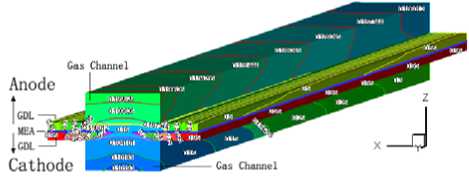
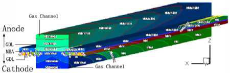
The physical model of a proton exchange membrane fuel cell is developed, which includes proton exchange membrane, catalyst layer of anode and cathode, gas diffusion layer of anode and cathode, gas channel of at different porosity of diffusion layer anode and cathode, current collector of anode and cathode. This is typical straight channel flow field and used broadly. The computational domain is shown in
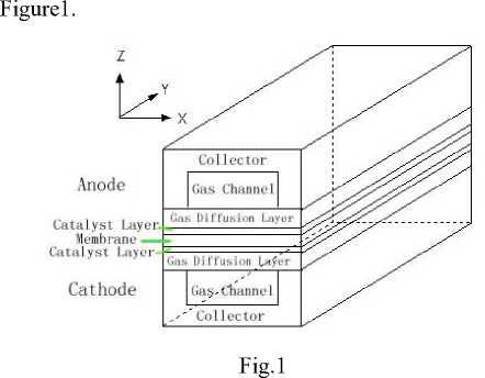
Figure1. Physical model of proton exchange membrane fuel cell
-
(1) Continuity equation
^ ( ^P )- + V- ( е р U ) = 0 ( 1 )
-
(2) Momentum Conservation
^РР Н! + v- ( ер U U ) = - е V p + е F + V- ( е т ) - U д t к
Where the £ is the porosity for a porous medium, p is the density of the liquid, U is the floating speed vector when the liquid in the porous medium, p is the pressure, F is the floating mass vector, T is the stress tensor, p is the liquid viscidity degree, к is the permeate ratio of the liquid through the porous medium. The right side of the Eq. ( 2 ) separately express the pressure, mass strength, viscosity strength, and the floating resistance of the liquid go through the porous medium.
-
(3) Conversation of energy equation
-
V- ( p U CpT ) = V- ( k ef V T ) + S T ( 3 )
Where, Cp is the specific heat capacity at constant pressure, keff is the effective thermal conductivity of gas mixture in porous medium, which can be yielded as a simple function of the gas mixture thermal conductivity in nonporous system, ST is energy source term which represents the rate of increase or decrease of energy due to heat generations or consumptions.
-
(4) Conservation of species equation
д ( е P X1 ) +V- ( е p U X, ) = V- N + 8, ( 4 ) о t
Where Xi is the mass fraction of specy i , Si is the produce speed of specy i adapt to the electrochemistry reaction. According to Fick’s law, the mass diffusion flux of the specy i in the porous medium is
Ni =— P D . X , ( 5 )
Where, Di is gas diffusion coefficient in nonporous material, which can be calculated from binary diffusion coefficient.
-
(5) Conservation of charge equation
The overall current in the catalyst layer are conservation. The current conservation equation is
V- i = 0 ( 6 )
The overall current is the sum of solid phase current and membrane phase current in the catalyst layer t = 1s + 1m 7)
The solid phase current and membrane phase current unattached, and contacted each other by electrochemistry reaction. The current density in the two phases and the potential meet Ohm’s law:
jt =-V- ( - ^ s Vфs ) =V- ( - ^ m Vф m ) ( 8 )
Where ф s and ф т separately express the solid phase potential and membrane phase potential.
-
(6) Electrochemistry reaction dynamics equation
The transfer current density is the system of electrochemistry reaction velocity, and associates the temperature, concentration of the species and the electricity potential between the solid and membrane phase. The relationship could be described by B-V equation
-
f a F a F 1 N
-
2.3 Boundary condition
j, = j0 1exp[ — (фs - Фт )] - exp[ — (фs - Фт )]ГП[Л] j
L RT RT j = 1
Where a a and a c separately express the transfer coefficient of the anode and cathode reaction. Л is the mol concentration of the reactant.
The boundary condition of the above equations is shown in Table 1.
Table 1 Boundary conditions
|
Boundary |
Boundary conditions |
|
Inlets of gas channels |
velocity weight: u = 0; V = 0; w = w in species: Xi = Xi ,in Anode: i = H 2 , H 2 O ;Cathode: i = O 2 , H 2 O temperature: T = T n |
|
Outlets of gas channels |
d u d v d w , , , p p out о x о x d x |
|
The front and behind end faces of MEA |
u = 0; v = 0; w = 0 ; T = T cell ; X- = 0 5 x |
|
The end face of anode |
u = 0; V = 0; w = 0 ; T = T cell ; ^ X L = 0 ; ^ = 0 5 x |
|
The end face of cathode |
, _ _ 5 X.. _ u = 0; v = 0; w = 0 ; T = Tcell ; —— = 0 ; 7 = П с еП d x |
|
The wall of the cell (YZ face) |
d u d v d w d Xj 5 T — = 0,— = 0,— = 0, —L = 0 ,— = 0 d x d x d x d x d x |
Table 2 Basic parameters of a PEMFC model
|
Parameters |
Value |
|
Membrane thickness |
5 X 10 -5 m |
|
Catalyst layer thickness |
2.5 X 10 -5 m |
|
Gas diffusion layer height |
2 X 10 -4 m |
|
Gas channel height |
8 X 10 -4 m |
|
Current Collector height |
1.2 X 10 -3 m |
|
Gas channel length |
5 X 10 -2 m |
|
Gas channel width |
2 X 10 -3 m |
|
Current Collector width |
4 X 10 -3 m |
|
Cell Temperature |
343K |
|
Anode inlet flux velocity |
1 X 10 -7 Kg/s |
|
Mass fraction of H 2 |
0.8 |
|
Cathode inlet flux velocity |
1 X 10 -6 Kg/s |
|
Mass fraction of O 2 |
0.9 |
-
2.4 Model parameter
3.1 The performance
The basic parameters referred in the proton exchange membrane fuel cell 3D model are shown in Table 2.
III Results and discussion
-
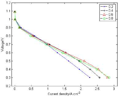
Figure2. Performance of proton exchange membrane fuel cell
3.2 The current density distribution
Fig.2 shows the polarization curves for different porosity at 0.2, 0.4, 0.6 and 0.8. The simulation results displays that the cell’s performance at higher porosity is better than at lower porosity when the cell is at higher current density. It is opposite when the cell is at lower current density. The cell with a porosity of 0.2 has almost the same current density at the lower current density with the porosity of 0.8 when it is at 0.8V. The fuel cell’s polarization curves departs the linearity relation with the voltage attenuates rapidly with the lower porosity when the cell at lower voltage section (e.g. under 0.7V), which put up biggish concentration difference polarization especially when the cell at the porosity of 0.6V. The fuel cell has best performance at the porosity of 0.8 while the worst at 0.2. The reason is that the reactant concentration of the electrode surface begins to change when the fuel is consumed. For example, the cell release current at the same time consumes oxygen when oxygen is provided to the cell’s cathode, which leads to the oxygen falling across resistance while being transferred. There are two troubles when the mass is been transferred. One is the space resistance, the second is flooding. The space resistance is mainly aroused by the mass transmission and reaction distinction between the flow channel and the ridge part of the flow flied board. The liquid state water bring that the millipore in the diffusion layer occurs to jam which influences the normal gas diffusion. The lower the porosity, the worse jam will be occurred in the diffusion millipore, and with a more rapid voltage decrease.
(a) 0.2
(b) 0.4
(c) 0.6 (d) 0.8
-
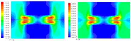
Figure3. The current density distributions at Y = 0m slice face with the porosity of 0.2, 0.4, 0.6 and 0.8
-
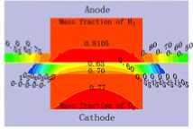
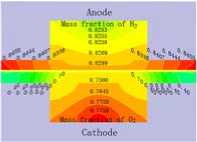
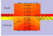
3.3 Distribution of gas concentration
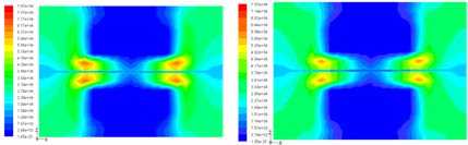
Fig.4 displays the hydrogen and oxygen gas mass concentration distribution at the Y=0m section of XZ when the cell discharge potential of 0.6V with the diffusion layer porosity is 0.2, 0.4, 0.6 and 0.8. It can be seen that the hydrogen gas in the gas channel of the anode distributing uniformity with the mass fraction value of 0.8105 when the porosity is 0.2. Differently, the oxygen gas distribution grads are larger than this, decline from 0.77 to 0.65. The hydrogen gas distribution in the diffusion layer of the anode falls from 0.8105 to 0.50. On
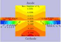
0.90 and 0.95. There are also two grads when the porosity is 0.6 or 0.8. The water mass fraction distribution is from 0.1068 to 0.3 at the inlet slice face, and from 0.3 to 0.6 along the gas channel direction in the slice face at X=2
X
10-3 m, respectively. In conclusion, the water mass fraction distribution minish from the gas diffusion layer to the gas channel in any XZ slice face, and increases along the direction of the gas channel. The higher the porosity is, the smaller the water mass fraction distribution grads will be, which explains that higher porosity is propitious to water transfer in the diffusion layer.
The current density distribution at the Y=0m section of XZ when the cell discharge potential of 0.6V is shown in the Fig.3. The diffusion layer porosity is 0.2, 0.4, 0.6 and 0.8, respectively. The highest current density region is the osculant district of the ridge part of the bi-polar board and the diffusion layer, which can be seen in the red zone from Fig.3. This is just the area which has the shortest gas and electron transport path. The current density above the flow channel is very small. It is difficult for oxygen to diffuse into the catalyst layer below the ridge portion at lower porosity of 0.2. The current density value reduces along the direction to the center of the ridge portion, the distribution grads of the current density is bigger, falls from the tiptop of 7.54 A / cm 2 to 0.397 A / cm 2 . It is contrary when at higher porosity e.g. 0.8. It is easier for oxygen diffusion, the distribution grads is less, falls down from the tiptop of 6.74 A / cm 2 to 1.59 A / cm 2 .
at different porosity of diffusion layer the contrary, oxygen gas distribution in the diffusion layer of the cathode drops sharply from 0.60 to 0. This situation will be relaxed when the porosity is 0.8, all the gas distribution grads is smaller than that at 0.2. Another result is that the hydrogen gas distribution grads are smaller than the oxygen gas distribution grads. There is some relationship with the molecule volume. Therefore, the higher the diffusion layer porosity is, the smaller the gas concentration grads of the diffusion will be. It is benefit for gas transport with high porosity, reducing the oxygen gas concentration grads and ridge part effect, especially when the oxygen gas diffuses from flow channel down to the ridge portion of the bi-polar board. The cell performance could be increased accordingly.
(a) 0.2
(b) 0.4
(a) 0.2
(c) 0.6 (d) 0.8
Figure4. The gas species distributions at Y=0m slice face with the porosity of 0.2, 0.4, 0.6 and 0.8
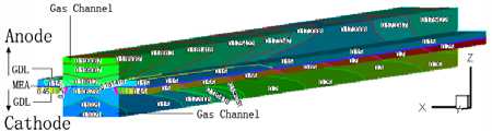
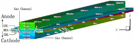
3.4 Water distribution
The water mass fraction distribution of the fuel cell with the cell discharge potential of 0.6V is shown in Fig.5. The oxygen is humidified before entering the flow channel in the cathode of the cell, thus water from the gas channel and the gas diffusion layer root in the building from reaction and transferring through the proton exchange membrane from the anode side to cathode side. The water mass fraction of the gas diffusion layer is always 0.95 when the porosity of the diffusion layer is 0.2. There are two grads when the porosity is 0.4. One is along the XZ slice face, the water mass fraction from the center of the diffusion layer to the boundary in the inlet slice face are 0.1065, 0.15, 0.35, 0.65, 0.75. The second grad along the YZ slice face, e.g. the water mass fraction distribution from the inlet to outlet of the slice face at X=2 X 10 -3 m are 0.75, 0.85,
(b) 0.4
(c) 0.6
(d) 0.8
Figure5. The water mass fraction distribution in fuel cell with the porosity of 0.2, 0.4, 0.6 and 0.8
The different in the anode is that the water mass fraction distribution grads in the diffusion layer along the gas channel direction are not as good as that in the cathode. The main distinction are that water mass fraction increases the gas channel along the channel direction in the cathode side, while depressed in the
anode side, although the depress extent is small. This is mostly because the net flux of water in the proton exchange membrane falls down from cathode to anode side, which means that the water concentration increasing in the diffusion layer of the anode side and then diffuse to the gas channel. Yet the gas concentration falls down near the outlet, which leads to the water building from reaction decrease. The water of the gas channel transfer to the diffusion layer in order to avoid the membrane drying at the anode side.
-
IV Conclusions
-
(1) The water brings the millipore in the diffusion layer occurs to jam, which influences the normal gas diffusion. The lower of the porosity, the worse jam will be occurred of the diffusion millipore, and with more rapidness of the voltage.
-
(2) The highest current density region is the osculant district of the ridge part of bi-polar plate and the diffusion layer. This happens to be the area which has the relatively shortest gas transport path and electron transport path. The current density above the flow channel is very small. It is difficult for oxygen to diffusion into the catalyst layer below the ridge portion when at lower porosity.
-
(3) The higher the porosity of the diffusion layer is, the smaller the gas concentration grads of the diffusion will be. It is benefit for gas transport with high porosity, reducing the oxygen gas concentration grads and ridge part effect, especially when the oxygen gas diffuses from flow channel down to the ridge portion of the bi-polar board. The cell performance could be increased accordingly.
-
(4) The water mass fraction distribution monishes from the gas diffusion layer to the gas channel in any XZ slice face, and increases along the gas channel direction. The higher the porosity is, the smaller the water mass fraction distribution grads will be, which explains that higher porosity is propitious to water transfer in the diffusion layer.
Acknowledgements
No.2009DFA63120), The National Science Foundation of China (No.50674006, No. 20876013, and Key Program No. 20636060).
References Model and simulation of proton exchange membrane fuel cell performance at different porosity of diffusion layer
- Baolian Yi, Fuel cell-Principle, Technology, Application, Chemical Industry Press, Beijing, 2003
- WEI Yong-sheng, Zhu Hong, Wang Li, Study and prospect of mathematical Model and numerical simulation for proton exchange membrane fuel Cell. The 3rd Asian Pacific Conference on Theoretical & Computational Chemistry,2007,9:169
- Wang C Y, Fundamental Models for Fuel Cell Engineering [J]. Chem Rev, 2004, 104(10):4727-4766
- Siegel N P, Ellis M W, Nelson D J, et al. A two-dimensional computational model of a PEMFC with liquid water transport [J]. J Power Sources, 2004, 128(2): 173-184.
- Zawodzinski Ta, Derouin C, Radzinski S, et al. Water-uptake by and transport through Nafion 117 Membranes, Journal of the electrochemical society, 140(1993): 1041-1047
- Adam Z. Weber, John Newman, Transport in Polymer-Electrolyte Membranes II. Mathematical Model, Journal of the Electrochemical Society, 151(2004): A311-A325
- Ying Wang, Minggao Ouyang, Three-dimensional heat and mass transfer analysis in an air-breathing proton exchange membrane fuel cell, Journal of Power Sources 164 (2007) 721–729
- Meng H, Wang C Y. Model of Two-Phase Flow and Flooding Dynamics in Polymer Electrolyte Fuel Cells [J]. J. Electrochem. Soc. 2005, 152 (9):A1733-A1741.
- Um S, Wang CY, Chen KS, Computational fluid dynamics modeling of proton exchange membrane fuel cells, Journal of the electrochemical society, 147(2000): 4485-4493
- Bernardi Dm, Verbrugge Mw, Mathematical-Model of a gas-diffusion electrode bonded to a polymer electrolyte, Aiche Journal, 37(1991): 1151-1163
- Atul Kumar, R. G. Reddy, Modeling of polymer electrolyte membrane fuel cell with metal foam in the flow-field of the bipolar/end plates, Journal of Power Sources 114 (2003) 54-62
- Peng Quan, Biao Zhou, Andrzej Sobiesiak, et al. Water behavior in serpentine micro-channel for proton exchange membrane fuel cell cathode, Journal of Power Sources 152 (2005) 131-145
- Ugur Pasaogullari, C. Y. Wang, Liquid Water Transport in Gas Diffusion Layer of Polymer Electrolyte Fuel Cells, J. Electrochem. Soc., 151(2004): A399-A406
- Xun Zhu, P.C. Sui, Ned Djilali, Dynamic behaviour of liquid water emerging from a GDL pore into a PEMFC gas flow channel, J. Power Sources.2007,172: 287-295.
- Luis Matamoros, Dieter Brüggemann, Numerical study on PEMFC’s geometrical parameters under different humidifying conditions, J. Power Sources, 2007,172: 253-264
- Y.H. Cai, J. Hu, H.P. M, Effects of hydrophilic/hydrophobic properties on the water behavior in the micro-channels of a proton exchange membrane fuel cell, Journal of Power Sources 161 (2006) 843–848
- Peng Quan, Ming-Chia Lai, Numerical study of water management in the air flow channel of a PEM fuel cell cathode, Journal of Power Sources 164(2007) 222-237
- FLUENT 6.3 User's Guide, 2006.
