Model-based Synthesis Method of Multiple Patterns Linear Arrays with the Minimum Number of Antenna Elements: A State Space Approach

Author: Jianfeng Liu, Jinhong Guo, Guowei Xu, Kuncheng Li
Journal: International Journal of Image, Graphics and Signal Processing(IJIGSP) @ijigsp
Article in issue: 6 vol.9, 2017.
Free access
In this paper, we propose a synthesis method for synthesizing the reconfigurable multiple patterns with the minimum number of antenna elements based on the state space model. The proposed method is to obtain the common element locations for the multiple patterns using fewer antenna elements within desired performance bounds. The proposed approach introduces the state-space method to represent the multiple patterns and then uses the multiple pattern data to construct a combined Hankel matrix which is used to estimate the model parameters from which the number of elements and the common element locations can be extracted. Numerical results show the effectiveness of the proposed methods.
Multiple patterns, state space model, antenna pattern synthesis, non-uniformly spaced arrays
Short address: https://sciup.org/15014194
IDR: 15014194
Text of the scientific article Model-based Synthesis Method of Multiple Patterns Linear Arrays with the Minimum Number of Antenna Elements: A State Space Approach
Published Online June 2017 in MECS
Our work is mainly to study the synthesis of a desired multiple patterns with as few elements as possible. Recently, some non-uniform linear array reconstruction techniques are proposed [1-5]. Despite these synthesis methods give good performance, when applied to the problem of the reconfigurable multiple patterns, those methods failed because of the change of the optimal element locations with different patterns. In this paper, this problem which is solved by the state-space synthesis method will be shown. Note that although the method proposed by Y. Liu et al. in [3] is the base of our method, our method is another implementation which is totally different from the above-mentioned method. By using the proposed methods, we can use a single antenna array to generate two or more radiation patterns, the optimal common element locations can be computed for the multiple patterns and the minimum number of elements can be determined, also the excitations of the multiple patterns can be obtained.
-
II. Data Model
It is assumed that the reconfigurable linear array antenna be composed of M identical elements with equal spacing Δ d , which can generate multiple patterns by changing the element locations and phase. Therefore the corresponding array factor is given by
M - 1 2 π Δ di
Gk ( θ ) = ∑ Ike λ , θ ∈ (0,180 o ), i = 0,1... M - 1, k = 1, 2... K (1)
i =0
where λ denotes the wavelength, θ is measured from the endfire of the linear array antenna, K is the total number of the desired pattern, and I k denotes the complex excitation of the ith element for the kth pattern.
Defining u = cos ( θ ) and d =Δ di respectively, then Eq. (1) can be rewritten as
M - 1 2 π d i
Gk ( cos - 1( u )) = ∑ I i ke λ , u ∈ ( - 1,1) (2)
i = 0
The array factor is sampled uniformly at N spaced points over the observation range u ∈ ( - 1,1) , then the sampled array factor of the k th pattern is expressed as
M - 1 - j 2 π d i n
Gk ( cos - 1( n )) = ∑ I i ke λ N , n =- N ,... N (3)
N i = 0
According to the sampling theorem [1], for the M -element uniform antenna array with the half wavelength spacing, N ≥ 2 M - 1 must be satisfied.
Generally, N = 2 M 4 M can be required.
2 π
Define ω = d , then Eq. (3) can be written as iλN i,
M - 1
G1 ( n ) = X I k e * , n = - N ,... N (4)
i = 0
Introduce the parameter m , then Eq. (4) can be also written as yk (m) = G (m - N) = X Ikeiro-Ne- M”, m = 0,....2 N (5)
i = 0
-
III. State Space Representation for the Desired Multiple Patterns
In this section, we will connect a relationship between the state space model and the desired sampled multiple patterns. As shown in Eq. (5), the kth sampled array pattern can be considered to be a sum of M complex exponentials. Such a signal is assumed to be the output of a self-generating system. It means that a special ARMA model is employed whose poles are all on the unit circle and input powers are all 0’s, which is expressed as yk (m) = '^apyk (m - P) k=1,2-K (6)
p = 1
Here we introduce the state space method to model the desired sampled multiple patterns. The state space representation for the desired pattern at the mth sampling point for the kth pattern is defined as [5,6,7]
X k (m +1) = FX k (m ) yk ( m ) = hX k ( m )
where Xk(m) is a M x1 state vector at the mth sampling point for the kth pattern and F is the state transition matrix of size Mxm .From Eq. (7), after some manipulations, we have yk (m) = hFm Xk (0) (8)
then the sampled data yk ( m ) is used to form the forward Hankel matrix which is written as
|
Where |
Y f = [ Y 1 Y f 2 Y 3 ... Y K ] |
(9) |
|
' yk (0) y k (1)-- y k (2 N - L +1)" |
||
|
Y f k = |
y k (1) y k (2)-- y k (2 N - L + 2) |
(10) |
|
_ y k ( L - 1) y k ( L )■■ . y k (2 N ) ] L x ( 2 N - L + 2) |
Generally, the parameter L is chosen between 4 N /3 and 6 N /3 . Combining Eq. (8) with Eq. (9), then Eq. (9) can be further factorized as follows:
Y f = [ h hF1 hF 2- hF L - 1 ] T [ X 1 X 2- X K ] = 0Ф (11)
Where
X k =[ X k (0) FX k (0)-- F 2 N - L + 1 X k (0) ]
[ h hF1 hF2- hF L 1 ] T = 0 (12)
where [ ] T denotes the matrix transpose.
-
IV. The Combined Matrix Structure
Because the solutions for the element positions can not be complex numbers, the forward-backward combined matrix must be employed. According to Eq. (9), the backward Hankel matrix is similarly expressed as
Yb = [ Y b Yb Y Y ]
Where
"[ y k (2 N )] *
,k_ [ y k (2 N - 1)] *
[ y k (2 N - 1)] * [ y k ( L - 1)] *'
[ y k (2 N - 2)] * [ y k ( L - 2)] *
[ y k (2 N - L + 1)] * [ y k (2 N - L )] * [ y k (0)] *
L x (2 N - L + 2)
where (.)* denotes the complex conjugation. Hence the combined matrix structure constructed by the forwardbackward Hankel matrix is written as
Y fb = [ Y f Y b ] (15)
thus state space representation for the combined matrix structure can be written as
where Xkb = [ f 2 N - L + 1 X k (2 n ) f 2 N - L X k (2 n ) • • X k (2 n ) ]
-
V. Proposed Method
To obtain much more freedom and minimize the number of array elements, the synthesis of a non-uniform spaced array is desired. In this paper, we use the low-rank matrix to approximate the forward-backward data matrix, so the SVD method must be employed. Therefore Eq. (16) can be decomposed as [8,9,10]
Г X
Y fb = [ ^ UT ] 1
=0Ф
where X denotes the diagonal matrix composed of the P dominant singular values ^ > ^ 2 • • • > ^ .
U , V denote the left and right singular vector respectively corresponding to the dominant singular values .
Now we focus on the choice of ^ > ^2 • • • > ^ . Generally, there shouldn't be zero singular values for the forward-backward data matrix formed by the desired patterns[12]. However, the number of principal singular values is always less than the total number of singular values which correspond to the number of elements for the desired antenna arrays. That means that we can neglect the very small values to reconstruct a low-rank approximation matrix, which corresponds to a new antenna array composed of fewer array elements. Typically, the singular values beyond P should be equal to zero, but in practice all of the singular values are not zero but close to zero. The value P is chosen as follow.
Consider the singular value 5P so such that [11,12]
d, =3[ ln(.)] , p = 1,2... p(23)
p where 3 denotes the imaginary part. The estimated excitations of multiple patterns are given as
I = [v hv]-1v H g(24)
where I , V and G are shown in (25),(26) and (27)
respectively.
« 10-4 ^ max
where P is the number of significant decimal digits. In our simulation, as mentioned in section VI, q = 2 ~ 3 can obtain good performance.
Hence the low rank approximate matrix of the combined matrix Y fb is shown as [13,14,15]
Y fb = U 1 У 1 V 1 H = u 1 У 1/2 У 1/2 V 1 H =0 ф (19)
which approximates the desired multiple patterns that can be generated by fewer elements, where (.) H denotes the complex conjugate transpose.
According to Eq. (18), we can obtain (0 = U У 12 . From Eq. (12), 0 and 02 can be obtained as following:
T
0, =[ h i h i F 1 h i F 2- --hF L - 2 J
T
02 = [ hF 1 hF 2- h F L - 1 J
where [ f denotes the matrix transpose. From Eq. (20), we can easily obtain the following equation:
(0 F = 02, that is F = 0f(02 (21)
where (.) † denotes the pseudo-inverse.
Using eigenvalue decomposition for the parameter matrix F ˆ , i.e
I1
I 1 I 2 IK
y 1(1) y 2(1) yK (1)
y 1(2 N ) y 2(2 N ) yK (2 N )
The algorithm is summarized as follows[12]:
Step 1: Employing the sampled array factor y k ( m ), m = 0...2 N to form the forward-backward combined data matrix
Y f b = [ У f Y b ]
Step2: Performing SVD on Y fb and obtaining the approximate the forward-backward data matrix Y ˆ fb
Г У.
Y fb = [ U 1 U 2 ] 1
J> b = и 1 Z i V
H
У 2
V 1 H
V 2 H
Step3: Factorizing the pre-processed Y fb to obtain (0 , i.e.:
P
F = У up uHj =U p=1
U H
where U = [ u u-Up ] , vp = e j® p , p = 1,2... P .
It is worthy to note that the above-mentioned diagonal matrix directly corresponds to the common element positions of the antenna array elements which can be computed from the diagonal elements of this matrix. Hence, the estimates of the common element positions can be computed as follows:
(0 = U 1 У 1/2
Step4: Computing the model parameter F ˆ using Eq. (19), Eq. (20) and Eq. (21)
F1 = 0^(02
Step5: Performing eigenvalue decomposition for the model parameter F to obtain е”Юр , i.e.
P
F ˆ = ∑ u p u p Hej ω p p = 1
Step6: the estimates of the common element positions can be computed as follows:
dˆ =ℑ[ln(ejωp)]Nλ,p=1,2...P p 2π , , where ℑ denotes the imaginary part. The estimated excitations of multiple patterns are given as
I = [ V H V ] - 1 V H G (28)
where I , V and G are shown in (25),(26) and (27) respectively.
According to our further study[12], the state-space method, the forward-backward matrix pencil method and extended matrix pencil method presented respectively by Y. Liu et al. in [2,3] are related and show nearly the same performance for the synthesis of the shaped-beam patterns. Hence, they are statistically equivalent. However, the state-space method is computationally more efficient in that only the eigenvalues of a P × P matrix have to be computed [6]. Because of the same performance between our method and Y. Liu’s method shown in [2,3], the following numerical simulations mainly focus on the validity of our method for multiplepattern designs.
-
VI. Simulation Results
A complicated multiple-pattern is considered shown in the literature[16] with Fig. 2, which is composed of a pencil pattern, a flat-topped pattern, and a cosec-squared pattern. The multiple-pattern is generated by using 20 uniform elements with the half wavelength spacing. In this simulation, L = floor(4N / 3) and N=4Mare set respectively. Fig.1 shows the reconstructed patterns for the desired multiple patterns with the state space method. As can be seen from Fig.1, the proposed method accurately reconstructs the desired multiple patterns with only 16 elements on the common element locations. Table1 lists the optimized common element locations. The advantage of the proposed method can be further verified by observing the distribution of singular values and the poles shown in Fig.2. As shown in Fig.2, all of the poles are exactly located on the unit circle (shown in Fig. 2(a)) and the singular values after the 16th value are nearly close to zero (shown in Fig. 2(b)). The very small singular values can be discarded because those values make no contribution to the reconstruction. This is the reason that the proposed method can save the number of antenna elements. In this case, the number of antenna elements is reduced nearly 20%. Fig. 3(a) and Fig. 3(b) respectively show the optimized the phase and amplitude distributions of the reconstructed multiple patterns by using the proposed method with 16 elements. As shown in Fig.3, both of the reconstructed pencil and flat-topped pattern have the symmetry amplitude-phase distributions, because the desired pencil and flat-topped pattern are axis symmetry. However the reconstructed cosec-squared pattern have the asymmetry amplitude-phase distributions, because the desired cosec-squared pattern is axis asymmetry.
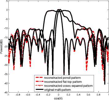
Fig.1. Multiple patterns synthesized by [16] with 20 elements and the patterns reconstructed by the proposed method with 16 elements
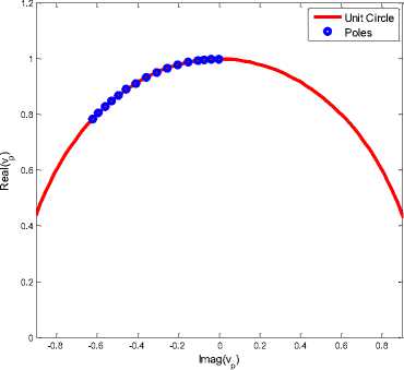
(a) Poles distribution
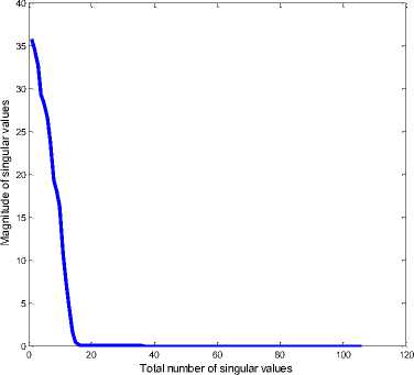
(b) Singula r values distribution
Fig.2. Distribution o f singula r values and the poles
Model-based Synthesis Method of Multiple Patterns Linear Arrays with the Minimum
Number of Antenna Elements: A State Space Approach
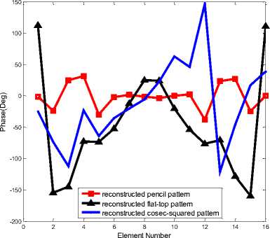
(a) Phase distribution
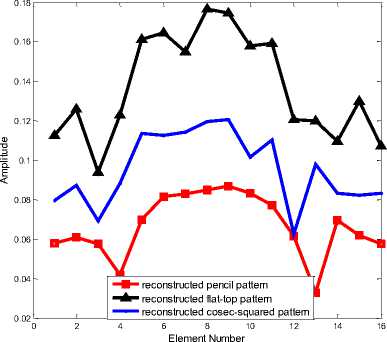
(b) Amplitude distribution
Fig.3. Element amplitude-phase distributions of the multiple patterns reconstructed by the proposed method with 16 elements
Table 1. Optimized Common Element Location of The Reconstructed Multiple Patterns with 16 Elements Shown In Fig.1
|
Element No. |
Position d ˆ p / λ |
Element No. |
Position d ˆ p / λ |
Element No. |
Position d ˆ p / λ |
|
0 |
0.0045 |
6 |
3.2705 |
12 |
7.0708 |
|
1 |
0.4836 |
7 |
3.9577 |
13 |
7.5649 |
|
2 |
0.9546 |
8 |
4.6778 |
14 |
8.0694 |
|
3 |
1.3419 |
9 |
5.3711 |
15 |
8.5489 |
|
4 |
1.9451 |
10 |
6.0244 |
||
|
5 |
2.6149 |
11 |
6.6089 |
-
VII. Conclusion
A state-space synthesis method that reconstructs multiple patterns with the minimum number of elements is presented. The new synthesis method uses the sampled multiple pattern data that is represented by state-space model to form a combined Hankel matrix. There exists a constraint on the distribution of the poles in the combined Hankel matrix which achieves more accurate and robust synthesis performance consequently. By using the proposed methods, the optimal common element locations are found, individual amplitudes and phases for a multiple patterns are obtained, and the number of antenna elements is determined, the number of antenna elements can be saved nearly 20%.
References Model-based Synthesis Method of Multiple Patterns Linear Arrays with the Minimum Number of Antenna Elements: A State Space Approach
- Y. Liu, Z. Nie, and Q. H. Liu, “Reducing the number of elements in a linear antenna array by the matrix pencil method,” IEEE Trans. On Antennas and Propagation, vol.56, no. 9, pp. 2955-2962, 2008.
- Y. Liu, Q. H. Liu, and Z. Nie, “Reducing the number of elements in the synthesis of shaped-beam patterns by the forward-backward matrix pencil method,” IEEE Trans. On Antennas and Propagation, vol. 58, no.2, pp.604-608, 2010.
- Y. Liu, Q. H. Liu and Z. Nie, “Reducing the Number of Elements in Multiple-Pattern Linear Arrays by the Extended Matrix Pencil Methods,” IEEE Trans. On Antennas and Propagation, vol. 62, no. 2, pp. 652-660, 2014.
- Ali Akdagli and Kerim Guney, “Shaped-beam pattern synthesis of equally and unequally spaced linear antenna arrays using a modified tabu search algorithm,” Microwave and Optical Technology Letters, vol. 36, no. 1, pp. 16-20, 2003.
- Soumyo Chatterjee, Sayan Chatterjee, and Dipak Ranjan Poddar, “Synthesis of linear array using Taylor distribution and Particle Swarm Optimisation,” International Journal of Electronics, vol. 102, no. 3, pp.514–528,2015.
- B. D. Rao and K. S. Arun, “Model based processing of signals: a state space approach,” Proceedings of the IEEE, vol. 80, no. 2, pp. 283-309, 1992.
- B. D. Rao, “Relationship between matrix pencil and state space based Harmonic retrieval methods,” IEEE Transactions on Acoustics, Speech, and Signal Processing, vol. 38, no. 1, pp. 177-179, 1990.
- H. B. Kekre, Tanuja Sarode, and Shachi Natu, “Performance Comparison of Watermarking Using SVD with Orthogonal Transforms and Their Wavelet Transforms,” International Journal of Image, Graphics and Signal Processing, vol.7, no.4, pp.1-18,2015.
- G. P. Hegde, M. Seetha, “Subspace based Expression Recognition Using Combinational Gabor based Feature Fusion,” International Journal of Image, Graphics and Signal Processing,vol. 9, no. 1,pp.50-60,2017.
- Ashish M. Kothari,Ved Vyas Dwivedi, “Hybridization of DCT and SVD in the Implementation and Performance Analysis of Video Watermarking,” International Journal of Image, Graphics and Signal Processing, vol.4, no.5, pp.14-20,2012.
- Hua Chen, S. Van Huffel , and J. Vandewalle, “State-space based approximation methods for the harmonic retrieval problem in the presence of known signal poles,”Acoustics, Speech, and Signal Processing, IEEE International Conference on ICASSP '96, Atlanta, GA, vol.5, pp. 2924-2927, 1996.
- Jianfeng Liu, “Model-Based Synthesis of Shaped-Beam Patterns with the Minimum Number of Elements: A State Space Method,” International Journal of Electronics,5, May,2017,http://dx.doi.org/10.1080/00207217.2017.1326172.
- T. K. Sarkar, O. Pereira, “Using the matrix pencil method to estimate the parameters of a sum of complex exponentials,” IEEE Antennas and Propagation Magazine, vol.37, no.1, pp.48-55,1995.
- S. Y. Kung, K. S. Arun, and D. V. Bhaskar Rao, “State space and SVD based approximation methods for the harmonic retrieval problem,” J. Opt. Soc., vol.73, no.12, pp.1799-1811, 1983.
- F. Desbouvries, “Unitary Hessenberg and state-space model based methods for the harmonic retrieval problem,” Proc. of IEEE Radar, Sonar and navigation, vol.143, no.6, pp.346-348,1996.
- M. Durr, A. Trastoy, and F. Ares, “Multiple-pattern linear antenna arrays with single prefixed amplitude distributions: modified Woodward-Lawson synthesis,” Electron. Lett., vol.36, no.16, pp. 1345-1346, 2000.
