Model of a microchannel heat exchanger of a supercharger for heating water

Author: Wang Yibo, Golyanin Anton
Journal: Бюллетень науки и практики @bulletennauki
Section: Технические науки
Article in issue: 8 т.8, 2022.
Free access
The subject of the research is a model of a microchannel heat exchanger of a supercharger for heating water. The purpose of study is to simulate the heating effect of microchannel heat exchangers for heating water and to evaluate their effectiveness in practice. Research methods: comparison, synthesis, modeling, description, experimentation, graphical analysis. As a result of the study, the prerequisites for the energy conversion of the microchannel heat exchanger, the heating unit, the energy conversion unit, and the biofuel storage unit were considered and put together. The degree of implementation is complete. Efficiency of development - in order to enhance energy use and reduce losses in energy use, thereby protecting the environment and saving energy.
Microchannel heat exchangers, pulsed flow, enhanced heat transfer
Short address: https://sciup.org/14124772
IDR: 14124772 | UDC: 621.311.243 | DOI: 10.33619/2414-2948/81/32
Модель микроканального теплообменника нагнетателя для нагрева воды
Предметом исследования является модель микроканального теплообменника нагнетателя для нагрева воды. Цель исследования - смоделировать нагревательный эффект микроканальных теплообменников для нагрева воды и оценить их эффективность на практике. Методы исследования: сравнение, синтез, моделирование, описание, экспериментирование, графический анализ. В результате исследования были рассмотрены и сведены воедино предпосылки к преобразованию энергии микроканального теплообменника, блока нагрева, блока преобразования энергии и блока хранения биотоплива. Степень реализации полная. Эффективность развития - увеличение использования энергии и снижения потерь при использовании энергии, защита окружающей среды и экономия энергии.
Text of the scientific article Model of a microchannel heat exchanger of a supercharger for heating water
Бюллетень науки и практики / Bulletin of Science and Practice Т. 8. №8. 2022
UDC 621.311.243
Microchannel technical devices are products in which microchannel currents are used to influence (mechanically, thermally, chemically, biologically, etc.) an object.
Бюллетень науки и практики / Bulletin of Science and Practice Т. 8. №8. 2022
Microchannel technical devices are widely used for heat removal and supply as microchannel heat exchangers and microchannel heat dissipators. What distinguishes them from traditional heat exchangers, as mentioned above, is their high degree of compactness (tens of thousands of square meters of heat transfer surface per volume) as well as small characteristic channel sizes (the equivalent diameter being fractions of a millimeter). They can have both small overall dimensions and dimensions comparable to traditional heat exchangers. As in conventional heat exchangers, heat transfer in microchannel devices can be carried out by convective heat transfer of single-phase liquids as well as by using the heat of phase transitions.
The best-known fields of application of microchannel heat exchangers are cooling of electronic equipment, cryogenic and aerospace engineering. Attempts are being made to use microchannel heat exchangers in the energy industry. Application of microchannels allows to make such heat exchangers less metal-intensive and lighter than conventional tubular finned heat exchangers designed for transferring the same heat flow. This is due to the small size of the units along the gas flow path and the small wall thickness of the channels.
In this paper, the main experimental design is to measure and thus obtain the data parameters of the heat exchanger in the process of heating air and, by means of calculations, to obtain the optimum oscillation frequency in order to obtain the highest heat exchange efficiency.
Material and research methods
During the research phase, a functional diagram of the connection of the microchannel heat exchanger to the heat circuit was developed, the diagram is shown in Figure 1.
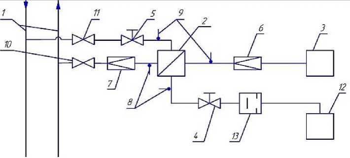
Figure 1. TO test diagram: 1 - heat network; 2 - test TE; 3 - tank of original fuel; 4,5 - regulating valves in heating and heated circuits; 6,7 - flow meters in heating and heated circuits; 8,9 - temperature sensors; 10,11 - inlet and outlet valves; 12 - heated fuel tank; 13 - solenoid valve
The heating circuit is filled using valve 10, then valve 11 is opened and the design flow rate is set using control valve 5. The design flow rate is monitored with the flow meter 7. Next, valve 4 is opened and the design flow rate in the heated circuit is set. The flow rate is controlled by the flow meter 6. After the steady state mode (5-10 seconds) the temperature readings are recorded by the DAC/DAC controller to which temperature sensors 8 and 9 are connected.
The TO is tested in pulse mode by switching the solenoid valve 13 on and setting the set frequency using a time relay (3; 4Hz)
Results and discussion
During the microchannel heat exchanger tests, the following parameters were automatically recorded: inlet and outlet temperatures of the heat transfer medium in the heating and heated circuit,
Бюллетень науки и практики / Bulletin of Science and Practice Т. 8. №8. 2022 as well as the fuel flow rate. Parameters in steady-state mode are presented in Table 1 Pulse mode readings are presented in Tables 2 and 3.
Table 1
MEASURED PARAMETERS IN STEADY-STATE MODE
|
Fuel consumption, l/m |
Heating medium temperature in the heating circuit |
Temperature in the heating circuit |
||
|
At the heat exchanger inlet (T1), °C |
At the outlet of the heat exchanger (T2), °C |
Initial air temperature (T3), |
Temperature of °C heated air (T4), °C |
|
|
0,81 |
76,955 |
69,503 |
11,047 |
53,525 |
|
0,77 |
76,816 |
69,800 |
11,094 |
50,689 |
|
0,73 |
76,934 |
71,453 |
11,017 |
52,824 |
|
0,67 |
76,671 |
71,195 |
11,014 |
58,184 |
|
Table 2 READINGS IN PULSE MODE WITH VALVE OPENING FREQUENCY 4HZ |
||||
|
Fuel |
Heating medium temperature in the heating circuit |
Temperature in the heated circuit |
||
|
consumption, l/m |
At the heat exchanger inlet (T1), °C |
At the outlet of the heat exchanger (T2), °C |
Initial air temperature (T3), |
Temperature of °C heated air (T4), °C |
|
1 |
76,410 |
69,047 |
10,512 |
49,802 |
|
0,94 |
76,416 |
69,540 |
10,605 |
51,279 |
|
084 |
76,316 |
69,773 |
10,780 |
53,348 |
|
0,72 |
76,681 |
70,885 |
10,860 |
56,220 |
For clarity, Figure 2 shows the dependence of temperature change of the heated medium on its flow rate for stationary and two pulse modes. As it can be seen from this graph for the pulse modes at the most part of flow rates the change of temperature of the heated medium is higher than in the stationary mode. These graphs were the basis for construction of power graphs for heated medium as a function of consumption for stationary and two pulse modes (Figure 3). From these graphs it is visible, that for all modes with increase of flow rate the power grows due to increase of heat transfer coefficient.
MEASURED PARAMETERS WITH VALVE OPENING FREQUENCY 3HZ
Table 3
|
Fuel consumption, l/m |
Heating medium temperature in the heating Temperature in the heated circuit circuit At the heat exchanger At the outlet of the heat Initial air temperature Temperature of inlet (T1), °C exchanger (T2), °C (T3), °C heated air (T4), °C |
|||
|
0,89 |
76,184 |
68,824 |
10,544 |
48,474 |
|
0,83 |
76,550 |
69,910 |
10,609 |
51,446 |
|
0,81 |
76,691 |
70,745 |
10,797 |
54,709 |
|
0,78 |
76,496 |
70,293 |
10,693 |
53,275 |
In particular, at a flow rate of 0.81 l/min the outputs are about the same. At the other flow rates, the power in pulse mode is 50-200 W higher than in steady-state mode. Figure 4 shows graphs of heat transfer coefficient as a function of flow rate for steady-state and two pulse modes.
The increase of heat transfer coefficient is from 5 to 12,5 % due to turbulence of coolant flow. The specific heat flux graphs are of practical interest (Figure 5). From which it is well visible, that for stationary mode specific heat flow increases from 47000 W/m2 to 57000 W/m2.
In pulsed mode at 4 Hz, the specific heat flux is almost constant with the flow rate and is at 55000 W/m2. Figure 6 shows plots of the calculated power and the experimental power for the medium being heated in steady-state mode. The calculated power is obtained using the heat transfer coefficient calculation technique given in [5]. At a flow rate of 0.78-0.81 l/min the power is almost the same, then the calculated power increases significantly.
Δt45НМ^г51^
℃ 40
0,660,68 0,7 0,720,740,760,78 0,8 0,820,840,860,88 0,9 0,920,940,960,98 1
—•— 3Hz —•— 4Hz —•— Steady g L/min
Figure 2. Flow diagrams for steady-state and two pulse modes
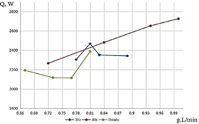
Figure 3. Heating medium power vs. flow rate plots for steady-state and two pulse modes
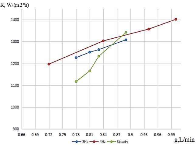
Figure 4. Heat transfer coefficient vs. flow rate plots for steady-state and two pulse modes q1,W/m2 58000 56000 54000 52000 50000 48000 46000

0,66 0,69 0,72 0,75 0,78 0,81 0,84 0,87 0,9 0,93 0,96 0,99
3Hz 4Hz Ssteady
g,L/min
Figure 5. Heat flux vs. flow rate plots for steady-state and two pulse modes
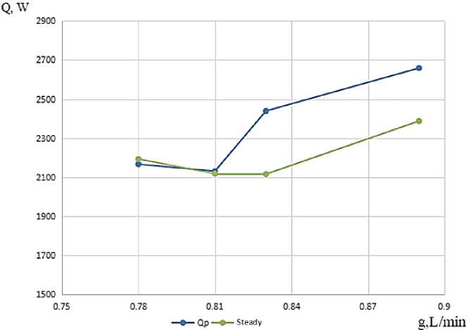
Figure 6. Plots of calculated and experimental heated capacity in steady-state mode
The heat transfer of a microchannel heat exchanger in pulse mode is more intense than in steady state mode due to increased turbulence in the flow.
k П А • c _
When the AFC is known as the hydraulic resistance in , deviation g , l. can be
A determined here:
P
A ( Q )
Where: P – Circle inlet pressure, Kpa.
g =
109 , 6886
= 0,1823343
If the flow rate of the heating medium is represented as g = g0 + g of the constant component and the deviation:
sf = 1 + —
g 0
s = 1 + O-182334432 = 1 , O82879
f 2.2
The heat transfer coefficient for microchannel heat exchangers (channel size less than 1 mm) is recommended to be determined according to the formula:
min( A f A s )
K =------ s
For A f A s adjusted for the heat transfer coefficient can be calculated according to the formula :
A
K = sf s ‘
0.25
K = ,---1,082879 = 386,7425
0,0007
Conclusion
-
1. One of the ways to increase the efficiency of a microchannel heat exchanger operating in different working environments is the correct balance of working environments. It depends on the time of heating the air to the required temperature in the heat exchanger-heater. From a review of literature sources, it was found that microchannel (compact) heat exchangers have the least inertia, heat transfer in which can be significantly improved due to pulsations of the fuel flow.
-
2. A prototype microchannel heat exchanger with stainless steel plates and 0.7 mm thick channels has been developed, the channels are separated by rubber gaskets. The heat transfer surface area was 0.13 m2.
-
3. A mathematical model of heat transfer of a microchannel heat exchanger with active plates in the form of an energy chain has been developed, which made it possible to determine the optimal frequency of interrupting flow equal to 0.65 Hz.
-
4. A hydraulic circuit diagram has been installed that allows thermal testing of the specified prototype of a microchannel heat exchanger, both in stationary and pulsed
-
5. The results of the conducted thermal tests of the prototype microchannel heat exchanger showed an increase in its heat transfer to 10% at a frequency of 0.65 Hz. For engineering calculations, a correction for the pulse mode has been introduced to the heat transfer coefficient, which has a sufficiently high convergence with the experimental results (less than 5%).
References Model of a microchannel heat exchanger of a supercharger for heating water
- Bergles A. E. New frontiers in enhanced heat transfer // ASME International Mechanical Engineering Congress and Exposition. American Society of Mechanical Engineers, 2000. V. 19067. P. 1-8.
- Tuckerman D. B., Pease R. F. W. High-performance heat sinking for VLSI // IEEE Electron device letters. 1981. V. 2. №5. P. 126-129.
- Choi S. U. S., Eastman J. A. Enhancing thermal conductivity of fluids with nanoparticles. Argonne National Lab. (ANL), Argonne, IL (United States), 1995. №ANL/MSD/CP-84938; CONF-951135-29.
