Modeling a methane-hydrogen flame using a vortex burner

Author: Dekterev A.A., Dekterev Ar.A.
Journal: Siberian Aerospace Journal @vestnik-sibsau-en
Section: Aviation and spacecraft engineering
Article in issue: 4 vol.26, 2025.
Free access
The article devoted to the development of a mathematical model and the calculation of a methane-hydrogen flame generated by a vortex burner. The combustion products of hydrocarbon fuels, used in energy and transportation facilities, are the main source of greenhouse gas emissions, leading to increased ambient temperatures and global climate change. Therefore, there has been a recent focus on reducing carbon dioxide emissions from aircraft gas turbine engines and industrial gas turbines. The use of methane-hydrogen fuel can significantly reduce CO2 emissions, but it also leads to changes in combustion modes. There is an increase in flame temperature and propagation speed, which can lead to increased NOx emissions and burnout of installation elements. Therefore, when designing combustion devices and chambers, it is important to study the various combustion modes of methane-hydrogen flames in detail. Computational fluid dynamics methods are widely used to solve these problems, but mathematical models of combustion for methane-hydrogen fuels in relation to vortex flames are still not fully developed. To optimize the design and operation of burner devices, it is necessary to conduct complex mathematical modeling of aerodynamic, heat, and mass transfer processes and combustion. This article describes models for these processes, which were justified and selected based on previous research by the authors for different types of flames. It also presents a mathematical model for calculating swirling methane-hydrogen flames using the vortex-resolving large-eddy simulation (LES) model to describe turbulence. Additionally, the article discusses FGM combustion models with a kinetic reaction mechanism developed at the Institute of Chemical Kinetics and Combustion SB RAS, as well as a discrete ordinate radiation transfer model. A comparison of the calculation results with experimental data obtained by the German Aerospace Research and Technology Center (DLR) showed that the selected mathematical models of turbulent aerodynamics, heat and mass transfer, and chemical reaction processes, as well as the calculation algorithms, make it possible to simulate, with sufficient accuracy for engineering practice, the combustion of methane-hydrogen mixtures in swirling flows formed by vortex burners, which are widely used in the combustion chambers of gas turbines. The computational resources required for such calculations are reasonably acceptable when using available cluster systems.
Vortex burner, methane-hydrogen mixture, flame, mathematical modeling, turbulence, combustion model, kinetic response mechanism
Short address: https://sciup.org/148333138
IDR: 148333138 | UDC: 536.46 | DOI: 10.31772/2712-8970-2025-26-4-518-531
Text of the scientific article Modeling a methane-hydrogen flame using a vortex burner
The combustion products of hydrocarbon fuels used in power and transport systems are the main source of greenhouse gases, leading to increased ambient temperatures and consequently global climate change. Consequently, reducing carbon dioxide emissions from aircraft gas turbine engines and industrial gas turbine units has recently received significant attention worldwide.
The use of methane-hydrogen fuel allows for a significant reduction in CO2 emissions. Furthermore, the use of hydrogen in the fuel mixture leads to a number of additional effects. Adding hydrogen to the fuel-air mixture, on the one hand, increases the engine's operating range, and, as is well known, burning leaner mixtures reduces the formation of nitrogen oxides (NOx). On the other hand, adding hydrogen to the fuel, due to its higher heat release, increases the flame front temperature and flame propagation velocity, which increases NOx emissions and can lead to burnout of system com- ponents [1]. Therefore, when developing burner devices and combustion chambers, a detailed study of the various combustion modes of methane-hydrogen flames is necessary.
In recent years, computational fluid dynamics (CFD) methods have been widely used to solve combustion problems. However, mathematical models of methane-hydrogen fuel combustion, as applied to swirl flames generated in combustion chambers, are currently insufficiently verified.
In the presented study, a comprehensive numerical method has been developed for calculating a swirling turbulent methane-hydrogen flame, which carefully takes into account turbulence, complex heat transfer, including radiation, and includes a combustion model with sufficiently detailed kinetic mechanisms and adequate consideration of the interaction of thermochemical processes with turbulence.
The authors' extensive experience in modeling a wide class of flames [2–5] allowed them to immediately settle on the eddy-resolving LES turbulence model for calculating the structure of a highly swirling flow realized in combustion chambers; the discrete ordinate model with WSSG for calculating radiative transfer in high-temperature gas flames.
In [6], the authors of the article conducted a comparative computational analysis of reaction mechanisms and turbulent combustion models for the problem of jet diffusion combustion of a methanehydrogen mixture. As a result, the following mathematical model was proposed for a swirling meth-ane-hydrogen flame.
Mathematical model
For multicomponent reacting flows, it is necessary to solve the equations of conservation of mass, momentum, energy, transfer of gas components and transfer equations for turbulent flow characteristics:
|p + V- ( p r ) = 0. d t
The expression represents the general form of the mass conservation equation and is applicable to both incompressible and compressible flows.
Conservation of momentum in an inertial frame of reference is described by the equation d R RR R R
—( p v ) + V • ( p vv ) = -V p + V • ( t ) + p g + F , 5 1
where p - static pressure; t - stress tensor described below; p g and F - respectively, the force of gravity and the external mass force.
The stress tensor has the form t = p
( V R + V v T ) - j V^ R I
wherr p - molecular viscosity; I - unit tensor. Второй член в правой части описывает эффект объемного расширения. The second term on the right-hand side describes the effect of volumetric expansion.
For highly swirling turbulent flows, such as those found in vortex burners, reverse flow zones with vortex core precession form along the flame axis. Using simple RANS turbulence models to simulate such flows leads to incorrect results. Therefore, in this study, the large eddy simulation (LES) method was used to calculate the turbulent flow characteristics. In this method, large eddy currents are resolved directly [6], while small eddies are modeled using a subgrid viscosity model. The components of the subgrid stress tensor t ij ■ are determined from a relation similar to the Boussinesq relation for RANS turbulence models.
here S i , j – strain rate tensor
т • • — т y
1 т kk b iJ = - 2 ц t S y , 3
S ij
d u u
[d x y 5 X i )
To calculate the subgrid viscosity µt in this work, the WALE (Wall-Adapting-Local-Eddy-Viscosity) model [7] was used. The eddy viscosity in this model is calculated as d d 3/2 (Si,jSi,j)
Ц т p L s
(Si, J Si,j )5/2 + (Sd + Sdj )5/4’ where Ls and Sid, j are defined as
L s = min( kd , C w V 1/3),
< d 1ГТ.~Г\ U -2 -
Si, J -I gi, J + gj, i I ,b i, Jgk, k gi, J
2\ /3
where k = 0.41 is the von Karman constant.; C w = 0.325.
To take heat exchange into account, the energy conservation equation is solved in the following form:
- ( p E ) + V- ( v ( p E + p )) = V- d t
( r ^
k ef V T - S hJ J J + ( T ’ v ) + Sh
\ J )
where k eff – effective thermal conductivity coefficient ( k + k t ), where k t is turbulent thermal conductivity coefficient determined by the turbulence model; J r j is diffusion flux component j . The first three terms of the right-hand side of the equation describe the transfer of energy due to thermal conductivity, diffusion of components and viscous dissipation, respectively, Sh is the heat source due to the heat of chemical reactions and other mechanisms.
Radiative heat transfer is accounted for using the discrete ordinate (DO) model [8]. The model solves the radiative heat transfer equation for a finite number of discrete solid angles, each of which is associated with a direction vector s , fixed in the global Cartesian system (x, y, z). The model allows control over the accuracy of angular discretization, while solving a number of transfer equations equal to the number of specified directions. The solution method is identical to that used for the fluid flow and energy equations.
Selecting a model for the absorption coefficient of a medium for the radiative heat transfer equation is a separate and major challenge in radiative heat transfer modeling. There are many models for calculating the absorption coefficient, ranging from detailed and labor-intensive approaches to rough approximations. A well-established approach for turbulent combustion problems is the weighted sum of gray gases (WSGGM) [9]. In this model, the spectral dependence of the gas absorption coefficient is represented as a sum of weighted gray gases.
To simulate turbulent combustion, we used a partially mixed combustion approach with the Flame-let Generated Manifolds (FGM) model [10]. The advantage of this method is that it allows the use of kinetic reaction mechanisms with a large number of reactions, while the computation time does not increase as significantly as, for example, when using the Eddy Dissipation Concept (EDC) model. In transient LES simulations, flamelet methods are currently the only option for applying detailed kinetic mechanisms with acceptable computational costs, and the FGM model is one of the most modern and widely used models.
The laminar flamelet model assumes that a flame is an set of laminar flamelets whose internal structure does not change significantly under the influence of turbulence. These laminar flamelets are combined into a turbulent flame using statistical averaging. The Flamelet Generated Manifolds (FGM) model assumes that the scalar evolution (i.e., realized trajectories on the thermochemical manifold) in a turbulent flame can be approximated by the scalar evolution in a laminar flame. In both the laminar flamelet model and the FGM, all components and temperature are parameterized by several variables, such as the mixture fraction, scalar dissipation, and/or reaction progress. Equations for these variables are solved in a three-dimensional CFD simulation, and local temperature values, mixture composition, and properties are reconstructed using pre-calculated flamelet tables. The FGM model differs fundamentally from the laminar flamelet model. For example, since laminar flamelets are parameterized by deformation, the thermochemistry always tends toward chemical equilibrium, as the deformation rate decreases toward the combustion chamber exit. In contrast, the FGM model is parameterized by the reaction progress variable, and the flame can be completely extinguished, for example, by adding air. FGM makes no assumptions about thin and intact flamelets, and the model can theoretically be applied to the stirred-tank reactor limit, as well as to ignition and quenching simulations.
The equations for all models are solved using numerical methods implemented using the control volume method, which utilizes unstructured computational grids. The computational grid is constructed using a detailed solid CAD model that takes into account the actual spatial geometry of the object under study. The SIMPLEC method is used to relate the velocity and pressure fields. The transport equation terms are approximated using second-order spatial and temporal accuracy schemes. The numerical methodology enables distributed computations using MPI technology with good efficiency when parallelized across a large number of computing cores.
Modeling of a swirling methane-hydrogen flame
In [11], researchers from the Department of Thermal Engineering and Thermal Engines at Samara National Research University presented a review of promising methane-hydrogen kinetic combustion models. A modified version of the chemical-kinetic mechanism of Wang 2018 (48 components and 308 reactions) was proposed [12]. It was shown that the mathematical combustion model of methanehydrogen mixtures predicts with satisfactory accuracy the boundaries of flame failure and upstream flashback observed in a model burner device and can be used to determine the boundaries of stable operation of the developed combustion chambers of gas turbine units when they are converted to hydrogen-containing mixtures.
In the work [13], specialists from the Institute of Chemical Kinetics and Combustion SB RAS, based on the detailed model AramcoMech 2.0 [14], presented two abbreviated kinetic mechanisms with different levels of detail for the combustion of CH4/H2 mixtures: RMech1 (30 components and 70 reactions) and RMech2 (21 components and 31 reactions), which describe well the combustion kinetics of one-dimensional flames under conditions typical for combustion chambers.
The authors previously tested the proposed mathematical models and kinetic mechanisms of combustion of a methane-hydrogen mixture on the problem of jet diffusion combustion [6]. Good agreement between the modeling results and experimental data conducted by DLR (German Aerospace Research and Technology Center) was demonstrated [15–17].
This paper examines the propagation of a swirling flame of a methane-hydrogen mixture from a Sydney Swirl Burner. A diagram of this burner device is shown in Fig. 1.
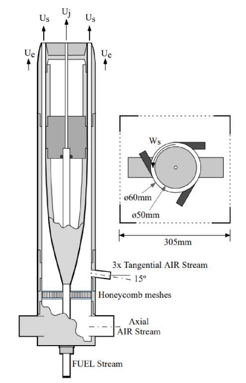
Рис. 1. Схема вихревого горелочного устройства Sydney Swirl Burner
Fig. 1. Schematic of the Sydney Swirl Burner
The device is characterized by a simple design with clearly defined boundary conditions, but at the same time it creates complex swirling flows that are not much different from the flows observed in real combustion chambers.
The experimental data for this burner device are given in [18; 19].
At the initial stage of burner modeling, the isothermal air flow mode N29S054 was considered with the following parameters:
-
– central jet velocity U j = 66 m/s;
-
– velocity of swirling coaxial flow U s = 29.74 м/с, twist parameter 0.54;
-
– external air flow velocity U e = 20 m/s.
To set the axial velocity of the central jet, a turbulent profile was used according to the power law [20],
UU} = C o U j
(
1 -
A 1 / 7 ,
where C 0 = 1.218 and r j = 1.8 mm. For a coaxial channel, the axial and tangential velocity components were specified using a similar expression.
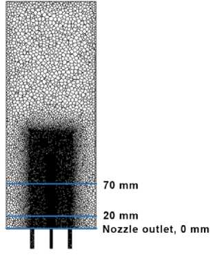
Рис. 2. Расчетная сетка в центральном сечении, 1,5 млн ячеек
Fig. 2. Computational mesh in the central section, 1.5 million cells
The calculations were performed in a full spatial setting, with a computational domain diameter of 0.13 m and a length of 0.35 m. Two types of unstructured computational grids were used: a basic grid with 1.5 million computational cells and a more detailed grid with 4.9 million computational cells. Figure 2 shows an example of the computational grid for the 1.5 million-cell variant, and also shows the burner cutoff line and lines at distances of 20 and 70 mm, for which the calculation results and experimental data were compared. The calculations were performed in a non-stationary setting with a time step of 5·10–5 s. To obtain averaged fields during the calculations, the values were averaged over time over 1 s of the physical process time.
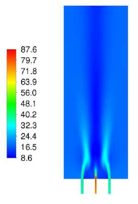
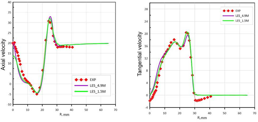
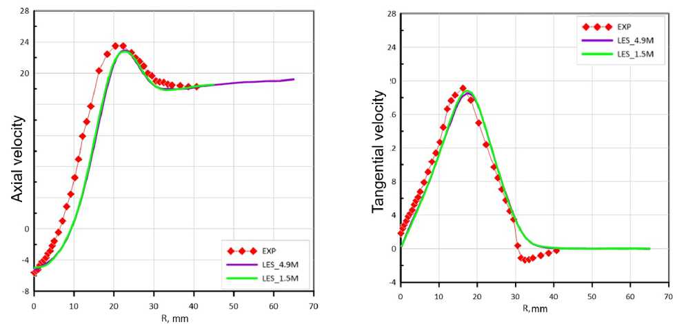
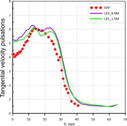
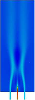
Fig. 3 shows the flow pattern generated by a vortex burner, showing the instantaneous and averaged velocity fields. It is evident that a strong reverse flow forms in the central region of the swirling flow, which will promote intensive gas mixing, good ignition, and stable combustion of the mixture. Figures 4 and 5 compare the calculated results and experimental data for the averaged velocity components and flow velocity pulsations at different distances from the burner exit. These figures demonstrate that the LES WALE turbulence model, even on a relatively coarse computational grid, allows for obtaining good results not only for the average flow characteristics but also for the pulsation ones, which is important for simulating the combustion process.
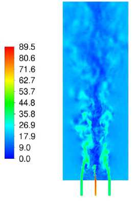
Рис. 3. Картина течения: а – мгновенное поле скорости, м/с; б – осредненное поле скорости, м/с
б
Fig. 3. Flow structure: a – instantaneous velocity field, m/s; б – mean velocity field, m/s
а
б
Рис. 4. Компоненты скорости, м/с: а – на расстоянии 20 мм от среза горелки; б – на расстоянии 70 мм от среза горелки
-
Fig. 4. Velocity components, m/s:
а – at a distance of 20 mm from the nozzle; б – at a distance of 70 mm from the nozzle
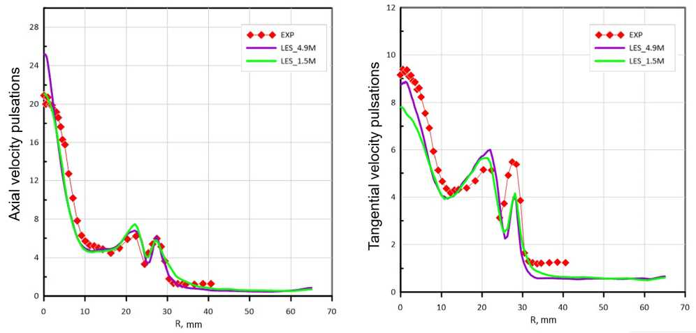
Рис. 5. Компоненты пульсации скорости: а – на расстоянии 20 мм от среза горелки; б – на расстоянии 70 мм от среза горелки (Начало)
-
Fig. 5. Velocity pulsation components: а – at a distance of 20 mm from the nozzle; б – at a distance of 70 mm from the nozzle (Beginning)
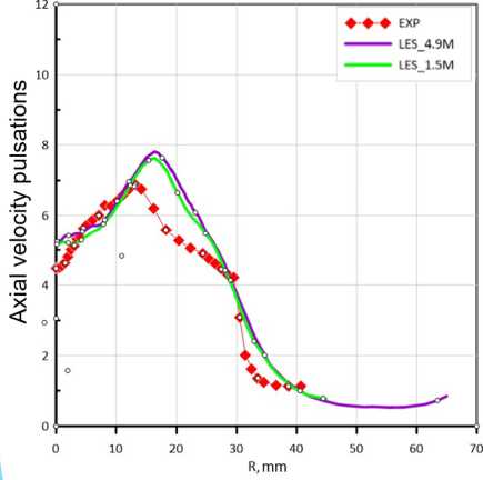
Рис. 5. Окончание
б
Fig. 5. Ending
б
■ 182.7
164.6
146.5
128.4
110.3
92.2
74.1
56.0
37.9
19.8
1.7
в
д
— 0.001
Г 0.001
0.001
0.001
0.001
0.001
0.001
0.000
0.000
0.000
0.000
е
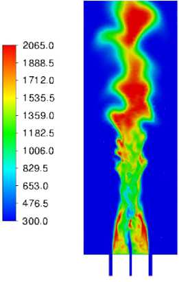
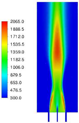
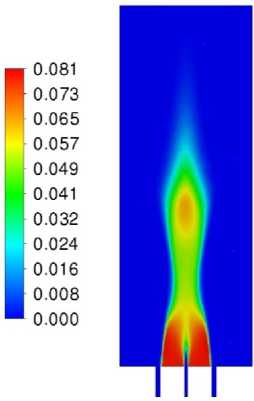
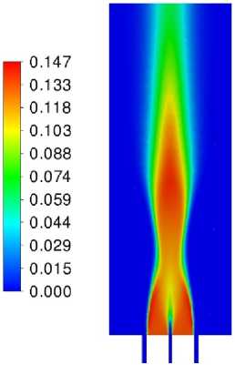
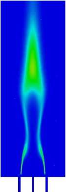
Рис. 6. Результаты моделирования горения метано-водородной смеси в вихревой горелке: а – мгновенное поле температуры, K; б – осредненное поле температуры, K; в – осредненное поле скорости м/с; г – осредненное поле массовой доли CO; д – осредненное поле массовой доли H2O; е – осредненное поле массовой доли OH
Fig. 6. Results of modeling the combustion of a methane-hydrogen mixture in a swril burner: а – instantaneous temperature field, K; б – mean temperature field, K; в – mean velocity magnitude m/s; г – mean mass fraction of CO; д – mean mass fraction of H2O; е – mean mass fraction of OH
Next, a simulation of the combustion of a methane-hydrogen mixture (SMH1 mode) was carried out for the conditions specified in the experiment [14].
Methane to hydrogen ratio in fuel 1:1.
Fuel speed U j = 140.8 m/s.
Speed of swirling coaxial air flow U s = 42.8 m/s, twist parameter 0.32.
External air flow velocity U e = 20 m/s.
The FGM model with the RMech1 kinetic mechanism was used to simulate turbulent combustion.
To set the boundary conditions for the gas velocity at the inlets, the same power law profiles were used as for the isothermal problem.
Due to high computational costs, combustion simulations were conducted only on a coarse computational grid of 1.5 million cells. The simulations were performed using available computing power (44 computational cores). Calculating one scenario, including averaging, required approximately 100 hours of computing time.
Figures 6–8 show the simulation results.
Fig. 6 shows the characteristic distributions of temperature, velocity and mass fractions of gas components in the flame of a vortex burner.
From the graphs presented in Fig. 7, 8, it is evident that the model as a whole qualitatively reproduces the temperature fields and concentrations of gas components, which allows us to recommend it for use in the development and design of combustion chambers aimed at burning advanced fuels based on methane-hydrogen mixtures.
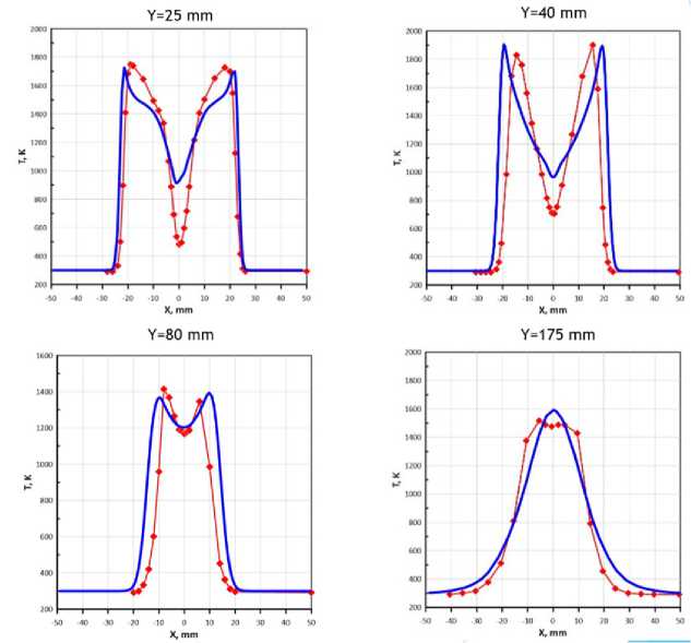
Рис. 7. Графики температуры на разном удалении от среза сопла, K. Красные точки – эксперимент, сплошная синяя линия – расчет
Fig. 7. Temperature at different distances from the nozzle, K.
Red dots – experiment, solid blue line – calculation
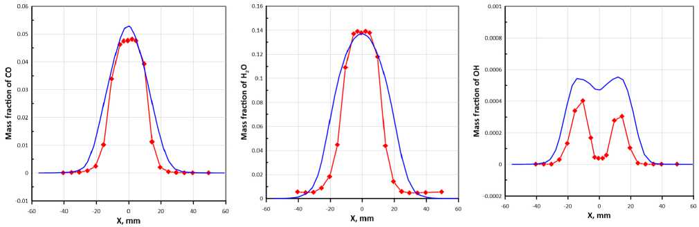
Рис. 8. Графики газовых компонент на расстоянии 175 мм от среза сопла. Красные точки – эксперимент, сплошная синяя линия – расчет
Fig. 8. Species mass fractions at 175 mm from the nozzle.
Red dots – experiment, solid blue line – calculation
Conclusion
A mathematical model for calculating swirling methane-hydrogen flames is presented. It utilizes the LES model for describing turbulence, the FGM combustion model with the RMech1 kinetic reaction mechanism, and the DO radiative transfer model.
Comparison of the calculation results with experimental data showed that the selected mathematical models of turbulent aerodynamics, heat and mass transfer, and chemical reaction processes, as well as the calculation algorithms, enable the combustion of methane-hydrogen mixtures in swirling flows generated by vortex burners, which are widely used in gas turbine combustion chambers, to be simulated with sufficient accuracy for engineering practice.
The computational costs required for such calculations are relatively acceptable when using available cluster systems.
Acknowledgements. This work was supported by the Ministry of Education and Science of Russian Federation, Agreement from 24.04.2024 № 075–15–2024–543.
