Modeling and Analysis of Disturbance on Three Phase Induction Motor at CFPP Tanjung Enim 3x10 MW Using Matlab/Simulink

Author: Destra Andika Pratama, Masayu Anisah, Andi Setiyadi
Journal: International Journal of Information Engineering and Electronic Business @ijieeb
Article in issue: 5 vol.14, 2022.
Free access
Three phase induction motor are very used widely, especially in industries because they bring advantages, namely simple and sturdy motor construction, relatively cheap prices, easier maintenance compared to other types of motors. At CFPP Tanjung Enim 3x10 MW, for example, a three phase induction motor used to support operational activities of the generator is a coal feeder with a motor power of 7.5 kW and a volt of 380 V. Damage to the induction motor at CFPP Tanjung Enim 3x10 MW has an impact on the a decrease in the performance of the Power Plant and can cause a loss of electricity production. Induction motor damage simulation is carried out by providing temporary disturbances, namely inter-phase disturbances and phase-to-ground faults which assume a sudden disturbance when the motor is operating normally. The parameters observed in this simulation are voltage (V), current (A) and motor rotation (Rpm). simulation results that have been carried out, it is found that disturbances in a three phase induction motor greatly affect the performance of the motor, such as when getting a phase to phase and phase to ground short circuits, the voltage will drop, the current will rise rapidly and rotation the motor will stop. By using Matlab software the author hopes to provide the right modeling to analyze the damage to the induction motor.
Matlab/Simulink, 3-phase Induction motor, Modeling, Analysis, short circuit
Short address: https://sciup.org/15018787
IDR: 15018787 | DOI: 10.5815/ijieeb.2022.05.03
Text of the scientific article Modeling and Analysis of Disturbance on Three Phase Induction Motor at CFPP Tanjung Enim 3x10 MW Using Matlab/Simulink
Published Online on October 8, 2022 by MECS Press
Induction motor is an electromechanical device used in colorful artificial operations to mechanical energy from electrical energy. Induction motors are used in colorful fields, including power generation, paper assiduity, petroleum, and manufacturing. Its use is substantially to drive pumps, conveyor belts, presses, elevators, etc. Of all being electric machines, induction motors are the most extensively used because they're strong, sturdy, affordable, dependable, easy to maintain and effective[1].
Damage to induction motors can be caused by colorful other factors related to the natural aging process and behavioral patterns of induction motors[2]. Electrical and mechanical connections are exemplifications of functional breakdowns. mechanical connection caused by load and unforeseen cargo changes, which can beget bearing damage and rotor rod fracture[3,4]. Electrical connection generally with a voltage source problem. For illustration, an inductive motor powered by an AC drive is susceptible to mains voltage due to the high frequence of the stator current factors and transients due to the length between the motor and AC drive due to the wiring of the flash voltage[6]. This electrical stress can beget a winding short circuit which means a complete breakdown of the induction motor[5].
In general, a induction motor has two main parts, namely the stator and the rotor. These sections are separated by a narrow air gap or what is commonly referred to as an air gap[8]. The distance between the stator and the rotor is separated by an air gap of about 0.4 millimeters to 4 millimeters[7]. There are two types of Induction motor when viewed from the windings on the rotor, namely the wound rotor and the squirrel-cage rotor. A three-phase winding A type of induction motor is the rotor (wound rotor). in which the rotor and stator windings are made of the same material[9]. Meanwhile, the 3-phase squirrel-cage rotor motor is a type of induction motor whose rotor construction is composed of several metal bars that are inserted through the slots in the motor rotor, then each part is joined by a ring. As a result of the union, there is a short circuit between the metal bars with other metal bars[10]. The working principle of this 3-phase electric motor is actually very simple[11]. When a 3-phase voltage source is applied to the stator coil, a rotating field will arise with a certain speed. The magnitude of this velocity can be measured using a formula Ns = 120 f/P. Where Ns is the rotational speed, f is the source frequency, and P is the motor pole[12].
CFPP Tanjung Enim 3x10 MW uses a induction motor to support the operating conditioning of the generating unit. Damage to the three phase induction motor at CFPP Tanjung Enim 3x10 MW can have a significant impact on the performance of the creator, causing power outages and costlosses.However, it can beget veritably serious damage with colorful types of damage similar as coil damage, reduced motor resistance, If damage to one of the motors in the creator isn't detected beforehand.
The author will focus more on the problem and limit it to the existing topic. Therefore, the authors emphasize the discussion of modeling and analysis of 3-phase induction motor faults at the CFPP Tanjung Enim 3x10 MW using Matlab Simulink.
2. Methodology 2.1. Data Collection and Research
Data collection was carried out to gain information in order to achieve exploration objects. The system of data collection was carried out in two ways, videlicet interviews and compliances. The interview system was carried out in collaboration with administrators and technicians of the CFPP Tanjung Enim 3x10 MW. This is related to the use of Simulink Matlab software as a way to model and dissect failures in three- phase asynchronous motors[13].
Compliances and analyzes carried out using Matlab software are simulations and analyzes related to damage that frequently occurs in induction motors at CFPP Tanjung Enim 3x10 MW. loss of electricity product and loss of cost at CFPP Tanjung Enim 3x10 MW.
(a)
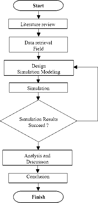
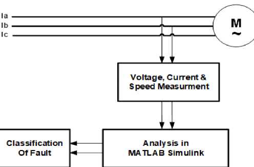
Fig.1. Research Process Flowchart (a) and Block Diagram Analysis (b)
(b)
The exploration methodology is quantitative exploration by recycling parameter data attained through the design of the original design simulation model and the system conditions are made as close as possible to the factual conditions[14].
In conducting the analysis, using Simulink in the Matlab program. is a program for numerical analysis and calculation which is an advanced fine programming language with the explanation of using the parcels and forms of matrices. Fig. 1a show the flowchart data collection and then Fig. 1b show block diagram depicts the relationship between the research's input, process, and output
-
2.2. The Induction Motor Parameters
-
2.3. The Techniques on Fault Detection
Poles = 4
Power = 7,5 kw
Nominal Voltage = 380 V
Nominal Current = 15,3 A
Frequency = 50 Hz
Speed = 1440 rpm
This research uses the simulation method, where this simulation uses the Simulink program in Matlab. The supporting data for the simulation, namely the parameters of the three-phase induction motor, were obtained by collecting data at the Tanjung Enim CFPP 3x10 MW. Voltage, Current and Rotation readings are carried out to determine the magnitude of the voltage and current measured at the input of the induction motor using Matlab Simulink[15]. Analysis with Matlab Simulink is carried out to determine the condition of the induction motor when it is running, whether it has failed due to damage to the induction motor or to obtain values and results from the simulations that have been carried out. Damage classification is the output of the analysis and simulation that has been done with Matlab Simulink, so that we can find out the failure of the induction motor, in this study the classification of damage to the induction motor is caused by the motor experiencing phase-phase and phase-ground faults.
-
2.4. Fast Fourier Transform (FFT)
Fast Fourier Transform (FFT) is a mathematical operation calculation technique used to transform analog signals into frequency-based digital signals. Fast Fourier Transform (FFT) divides a signal into different frequencies in a complex exponential function. Fast Fourier Transform (FFT) is an algorithm for calculating discrete fourier transforms quickly and efficiently. Because the signals in the communication system are continuous, the results can be used for Fourier transforms[16].
From the integral equation above, it can be seen that the Fast Fourier Transform (FFT) can be used to calculate the frequency, amplitude and phase values of a signal wave. Meanwhile, to calculate the frequency spectrum of a signal on a digital computer requires a Discrete Fourier Transform (DFT) algorithm. Discrete Fourier Transform (DFT) converts a time domain signal into a frequency domain signal[17].
Another faster algorithm is the Fast Fourier Transform (FFT). The working principle of FFT is to divide the sampled signal into several parts, then each part is solved by the same algorithm and the results are collected again[17,18]. There are three classes of FFT that are commonly used in DSP software, namely Decimation in Time (DIT), Decimation in Frequency (DIF) and Split Radix. The idea of the three types of FFT is that the data sequence iteration process is carried out differently and utilizes kernel functions that are symmetrical at a certain value in one period of a signal. Another type of FFT that has been used is parallel FFT where the data sequence is done using parallel computing so that the transformation process will be faster. Until now, the use of FFT in several software such as MATLAB 6.51 and Sound Forge 6.02 still has a limited resolution of 1 Hz[19]. Resolution can be interpreted as the separation power or sensitivity of a measuring instrument in obtaining the best measurement results so that it can distinguish the smallest changes from physical quantities. DFT and FFT have a resolution of fs/N where fs is the sampling rate (fs of data is taken in 1 second) and N is the number of sampled data. Generally this resolution limitation is overcome by using the windows function. However, the signal from this treatment is not in accordance with the reality or the actual frequency carried and depends on the selection of the type of windows function. Therefore, it is very important to compile DFT and FFT equations with higher resolution and then implement these equations into a program[16,20].
The Fourier transform is defined as:
∞ - j 2 π ft
x ( f ) = ∫ x ( t ) e dt
∞
∞∞
= ∫ x ( t )cos(2 π ft ) dt - j ∫ x ( t )sin(2 π ft ) dt (1)
∞∞
∞
∫ x ( t ) cos(2 π ft ) dt → ∑ x ( n ∆ t ) cos(2 π fn ∆ t ) ∆ t
-∞ n
= ∑ x ( n ∆ t ) cos(2 π nm ∆ t ∆ f ) ∆ t
n
n
N
In the time domain, the period of a signal is expressed as T = N∆t, while in the frequency domain f = fs/N where f represents the interval between frequencies and Fs = 1/∆t = N∆f. Thus, in equation (2) t∆f = 1/N which is the link between the time domain and the frequency domain. If the amount of data is less than fs, the resulting frequency is not precise. On the other hand fs must be 2f maximum to avoid aliasing the frequency near the sought frequency[19,21]. Aliasing is the phenomenon of the emergence of the same frequency from the transformation results where we cannot distinguish between the original frequency and the shadow frequency. In general, the Fourier transform uses a tool called a real-time spectrum analyzer which has been integrated into the chip to calculate discrete time domain signals coming from the microphone. To be able to analyze the frequency spectrum, in the DSP processor a Discrete Fourier Transform (DFT) program is arranged[22].
-
2.5. Development Of Simulink Model
3. Result and Discussion
-
3.1. Simulation in Matlab Software
In the simulation using Matlab Simulink, for the induction motor voltage source using an AC voltage of 6300 Volts. Then a measuring instrument is given to measure the input voltage before entering the Main Circuit Breaker (MCB)[25]. Furthermore, the voltage is entered into a step down transformer which reduces the voltage from 6300 Volt to 380 Volt according to the voltage requirements of the motor induction. At the incoming voltage to motor, measurements of voltage, current and frequency are carried out. Furthermore, measurements are made when the induction motor is running, while the parameters measured on the induction motor are motor speed. Fig. 3 show is a series of simulations to perform analysis on matlab simulink.
-
3.2. Measurement Analysis Results
The block model of an inductive motor system with a regulator was developed from the introductory features available in the Matlab/ Simulink Simulink library, using power systems, power electronics, control systems, and signal processing toolboxes[23]. The entire system modeled in Simulink is a unrestricted- circle control conforming of a factory, regulator, sample, comparator, feedback system, gain block, multiplier, timepieces, subsystems, integrators, and statespace model. The system, Subsystem, affair Gomorrah (compass), input source,etc [24]. Fig. 2a is a picture of the current regulator and Fig. 2b is the VDC Regulator used in the matlab simulink program
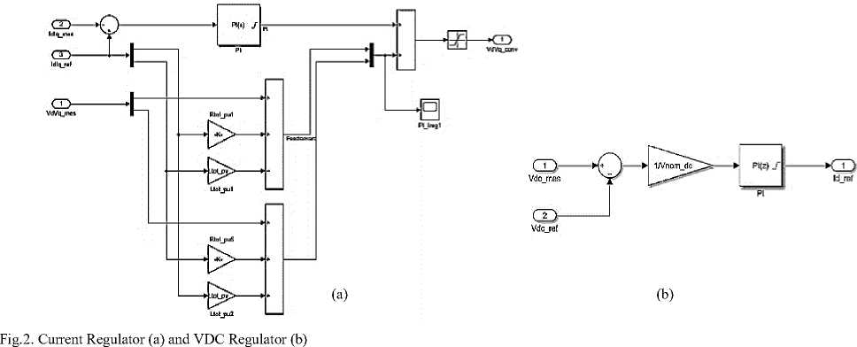
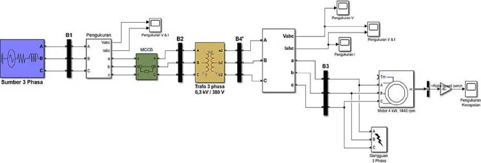
Fig.3. Simulation in Matlab Software
-
a. Condition of induction motor parameters when no problems occur or Normal Condition
Voltage (V)
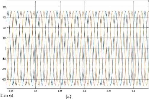
Fig. 4 show is a voltage (a), current (b) and speed (c) when the induction motor parameters are in normal condition
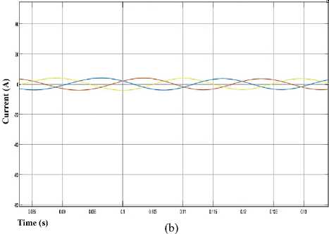
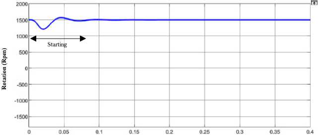
Time (s)
(c)
Fig.4. Voltage of Healthy Motor (a), Current of Healthy Motor (b) and Speed of Healthy Motor (c)
-
b. Induction motor parameter condition when there is a short circuit problem between phase to phase (failure condition of phase to phase).
Fig. 5 show is a voltage (a), current (b) and speed (c) when the induction motor parameters are in short circuit problem between phase to phase
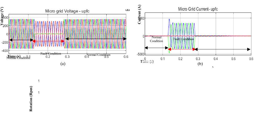
Time (s)
(c)
Fig.5. Voltage of Fault (a), Current of Fault (b) and Speed of Fault (c)
-
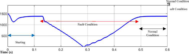
c. Induction motor parameter condition when there is a short circuit problem between phase to ground (failure condition of phase to ground).
Fig. 6 show is a voltage (a), current (b) and speed (c) when the induction motor parameters are in short circuit problem between phase to ground.
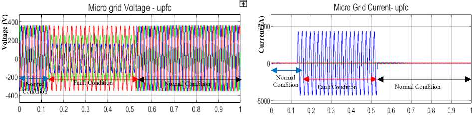
Time (s)
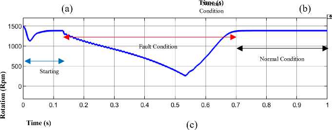
Fig.6. Voltage of Fault (a), Current of Fault (b) and Speed of Fault (c)
4. Conclusion
From the simulation results using Simulink Matlab for analysis of damage to the induction motor that has been carried out at CFPP Tanjung Enim 3x10 MW, it can be concluded as follows:
-
1. By modeling or simulating the failure of an induction motor, we can find out and have a basis for the type of damage to an induction motor from the electrical side.
-
2. Induction motor damage simulation is carried out by providing temporary disturbances, namely inter-phase interference and phase-to-ground faults which assume a sudden disturbance when the motor is operating
-
3. The results of the simulation, when the motor rotation voltage drop also decreases along with the loss of frequency, but the current will increase up.
normally. The parameters observed in this simulation are voltage (V), current (A) and motor rotation (Rpm).
The results of the simulation data for normal conditions and fault conditions on the induction motor that have been carried out can be seen in the table below.
Table 1. Simulation data using Simulink Matlab
|
No. |
Failure Type |
Value |
||||||
|
Vr (V) |
Vs (V) |
Vt (V) |
Ir (A) |
Is (A) |
It (A) |
Rotation (Rpm) |
||
|
1 |
Normal |
380 |
380 |
380 |
21 |
21 |
21 |
1.440 |
|
2 |
Phase - Phase |
6,5 |
303 |
310 |
3.565 |
3.748 |
80 |
0 |
|
3 |
Phase - Ground |
162 |
355 |
254 |
4.207 |
55 |
55 |
275 |
References Modeling and Analysis of Disturbance on Three Phase Induction Motor at CFPP Tanjung Enim 3x10 MW Using Matlab/Simulink
- E. Anbarasu and M. Karthikeyan, “Modeling Of Induction Motor and Fault Analysis,” Certif. Int. J. Eng. Sci. Innov. Technol., vol. 9001, no. 4, pp. 2319–5967, 2008.
- K. P. Diwatelwar and S. K. Malode, “Fault Detection and Analysis of three-phase induction motors using MATLAB Simulink model,” Int. Res. J. Eng. Technol., vol. 9001, p. 1643, 2008, [Online]. Available: www.irjet.net
- D. L. Kurniawan, I. Diah PK, and B. Yan Dewantara, “Analisa Gangguan Belitan Stator Pada Motor Brushless DC Menggunakan Matlab Simulink,” CIRCUIT J. Ilm. Pendidik. Tek. Elektro, vol. 5, no. 1, 2021, doi: 10.22373/crc.v5i1.7692.
- D. Zaenal, “Analisa Gangguan Stator Motor Induksi Fasa 3 Dengan Metode Current Signature Analisis Dan Monitoring Temperatur,” Epic J. Electr. Power, Instrum. Control, vol. 2, no. 2, 2019, doi: 10.32493/epic.v2i2.2897.
- U. Khasanah, S. Supari, and S. Heranurweni, “Simulasi Pengaturan Kecepatan Motor Induksi 3 Phasa Dengan Direct Torque Control Menggunakan Matlab,” eLEKTRIKA, vol. 9, no. 1, p. 13, 2018, doi: 10.26623/elektrika.v9i1.1109.
- P. Magister, B. Keahlian, T. Sistem, J. T. Elektro, and F. T. Industri, “Identifikasi Kerusakan Bearing Motor Induksi Berdasarkan Karakteristik Arus Stator Dengan Metode Artificial Neural Network Bearing Fault Identification of Induction Motor Based on Stator Current Characteristics Using Artificial Neural,” 2016.
- L. J. Sinaga, “Analisis Arus Asut Pada Motor Induksi Tiga Fasa Dengan Menggunakan Pengasutan Langsung (Dol) Dan Pengasutan Autotrafo,” Anal. Kesadahan Total dan Alkalinitas pada Air Bersih Sumur Bor dengan Metod. Titrim. di PT Sucofindo Drh. Provinsi Sumatera Utara, pp. 44–48, 2018.
- L. Hakim, “Analisa Kerusakan Motor Induksi 3 Fasa 75 Kw Pada Water Cooling Pump Dengan Metode Mcsa (Motor Currentsignature Analysis) Unit Blok 2 Pt Indonesia Power Pgu Semarang,” Univ. Semarang, pp. 0–106, 2021.
- Q. Han, T. Wang, Z. Ding, X. Xu, and F. Chu, “Magnetic Equivalent Modeling of Stator Currents for Localized Fault Detection of Planetary Gearboxes Coupled to Electric Motors,” IEEE Trans. Ind. Electron., vol. 68, no. 3, 2021, doi: 10.1109/TIE.2020.2973894.
- M. Hussain et al., “Stator winding fault detection and classification in three-phase induction motor,” Intell. Autom. Soft Comput., vol. 29, no. 3, 2021, doi: 10.32604/iasc.2021.017790.
- Bonnett Austin H, Soukup GC (1992) Cause and analysis of stator and rotor failures in three phase squirrel-cage induction motors. IEEE Trans IndAppl 28(4):921–937
- Bradford M (1968) Unbalanced magnetic pull in a 6-pole induction motor. IEEE ProcElectrEng 115(11):1619–1627
- M’hamed D, Cardoso AJM (2008) Air gap eccentricity fault diagnosis in three phase induction motor by the complex apparent power signature analysis. IEEE Trans IndElectr 55(3):1404
- Eschmann P, Hasbargen L, Weigand K (1958) Ball and roller bearings: their theory, design and application. K. G. Heyden, London
- Siddique A, Yadava GS, Singh B (2005) A review of stator fault monitoring techniques of induction motors. IEEE Trans Energy Convers 20(1):106–114
- Liang, B., Payne, B. S., Ball, A. D., &Iwnicki, S. D. (2002). Simulation and fault detection of three-phase induction motors. Mathematics and computers in simulation, 61(1), 1-15.
- Ye, Z., Wu, B., &Sadeghian, A. (2003). Current signature analysis of induction motor mechanical faults by wavelet packet decomposition. IEEE transactions on industrial electronics, 50(6), 1217-122
- K. . K. Pandey, P. H. Zope, and S. R. Suralkar, “Article: Review on fault diagnosis in three-phase induction motor,” IJCA Proceedings on National Conference ”MEDHA 2012”, vol. MEDHA, no. 1, pp. 53–58, September 2012, full text available.
- Dorrell DG, Thomson WT, Roach S (1997) Analysis of air-gap flux, current and vibration signals as function of a combination of static and dynamic eccentricity in 3-phase induction motors. IEEE Trans IndAppl 33:24–34.
- Bradford M (1968) Unbalanced magnetic pull in a 6-pole induction motor. IEEE ProcElectrEng 115(11):1619– 1627
- Hwang DH, Lee KC, Lee JH, Kang DS, Lee JH, Choi KH, Kang S et al (2005) Analysis of a three phase induction motor under eccentricity condition. In: 31st annual conference of IEEE industrial electronics society, IECON2005, pp 6–10
- Lee SB, Tallam RM, Habetler TG (2003) A robust on-line turn-fault detection technique for induction machines based on monitoring the sequence component impedance matrix. IEEE Trans Power Electr 18(3):865–872
- Vatsa, A. (2017). Fault diagnosis of induction motor using wavelets. International Journal of Research and Engineering, 4(4), 125-129.
- Altaf, S., Soomro, M. W., &Mehmood, M. S. (2017). Fault Diagnosis and Detection in Industrial Motor Network Environment Using Knowledge-Level Modelling Technique. Modelling and Simulation in Engineering, 2017.
- Benbouzid, M. E. H., Vieira, M., &Theys, C. (1999). Induction motors' faults detection and localization using stator current advanced signal processing techniques. IEEE Transactions on power electronics, 14(1), 14-22.
