Modelling of multilayer dielectric filters based on TIO2 / SIO2 and TIO2 / MgF2 for fluorescence microscopy imaging

Автор: Butt Muhammad Ali, Fomchenkov Sergey Alexandrovich, Ullah Anayat, Habib Mohsin, Ali Rabia Zafar
Журнал: Компьютерная оптика @computer-optics
Рубрика: Opto-it
Статья в выпуске: 5 т.40, 2016 года.
Бесплатный доступ
We report a design for creating multilayer dielectric optical filters based on TiO2 and SiO2/MgF2 alternating layers. We have selected Titanium dioxide (TiO2) for high refractive index (2.5), Silicon dioxide (SiO2) and Magnesium fluoride (MgF2) as a low refractive index layer (1.45 and 1.37) respectively. Miniaturized visible spectrometers are useful for quick and mobile characterization of biological samples. Such devices can be fabricated by using Fabry-Perot (FP) filters consisting of two highly reflecting mirrors with a central cavity in between. Distributed Bragg Re-flectors (DBRs) consisting of alternating high and low refractive index material pairs are the most commonly used mirrors in FP filters, due to their high reflectivity. However, DBRs have high re-flectivity for a selected range of wavelengths known as the stopband of the DBR. This range is usually much smaller than the sensitivity range of the spectrometer. Therefore, bandpass filters are required to restrict the wavelength outside the stopband of the FP DBRs. The proposed filter shows high quality with an average transmission of 97 % within the passbands and the transmission outside the passband is around 3 %. Special attention has been given to keep the thickness of the filters within the economic limits. It can be suggested that these filters are exceptionally promising for florescence imaging and narrow-band imaging endoscopy.
Fabry-perot filter, fluorescence microscopy, dielectric multilayers
Короткий адрес: https://sciup.org/14059606
IDR: 14059606 | DOI: 10.18287/2412-6179-2016-40-5-674-678
Текст научной статьи Modelling of multilayer dielectric filters based on TIO2 / SIO2 and TIO2 / MgF2 for fluorescence microscopy imaging
Thin film optics is well developed technology. Therefore, many devices such as passband filters, stopband filters, polarizers and reflectors are realized with the help of multilayer dielectric thin films [1], [2], [3]. These devices consist of alternating layers of high and low refractive index materials with particular thicknesses with good knowledge of their refractive index and absorption, Fig. 1. These devices work on the principle of multiple reflections between high and low index materials interface. Distributed Bragg Reflectors (DBRs) are quarter wave thick of the centre wavelength [4]. The high reflection region of a DBR is known as the DBR stopband, and can be obtained by the refractive index contrast between the constituent layers. A broad stopband can be realized by using high index contrast thin films. By inserting a half wave cavity between two highly reflecting mirrors governs an output at the desired wavelength [1]. This kind of device is known as Fabry-Perot (FP) filter. DBRs are the most commonly used mirrors in FP filters, due to their high reflectivity for specific range of wavelengths. FP has numerous applications in laser line filtering, astronomical observations, fluorescence microscope imaging and spectroscopic instrumentation.
In two photon fluorescence microscopy imaging, a fluorophore absorbs light at its excitation wavelength, and typically emits light at a longer wavelength. The emission spectra of the biological samples has high emission peak at 511 nm which is easy to detect [5] [6]
-
[ 7].Therefore, there is a need to develop such filter which can selectively transmit the emitted wavelength and block the excitation wavelength, thus improving the contrast for both sensing and imaging these fluorophores. DBRs consist of alternating layers of high and low refractive index materials. DRBs have high reflectivity for wavelengths around a central wavelength, which is governed by the optical thickness (refractive index x physical thickness) of the constituent layers, and in four times their optical thickness. DBR layers are therefore a quarter-wave thick of the central wavelength.
Distributed Bragg Reflectors (DBRs)
I I Low index material ZZ High index material.
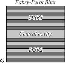
Fig. 1. Schematic diagram of (a) Distributed Bragg Reflectors, (b) Fabry-Perot filter
a)
Filter design and discussion
In this work, the designs of FP filters based on TiO2 / SiO2 and TiO2 / MgF2 are proposed at a central wavelength of 511 nm for biomedical bandpass filter for fluorescence microscopy imaging, Fig. 2. We tried to de- sign the filters with minimum number of layers and high transmission peak at central wavelength with high transmission and narrow width (FWHM). Open-source software, Open Filters, is used in this work to design and optimize the required filter, it uses transfer matrix method to analyse transmission and reflection of light from layers based on thicknesses and type of materials [8]. Design are optimized to reduce FWHM and maximum transmission for 511 by nm using needle synthesis method (It adds extra layers (called needle) to the design and each time it add a needle, transmission spectrum of filter is calculated. The optimal position of needle to be added between the layers of a filter is based on derivative of Merit Function with respect to thickness of thin layer. The position where derivative is negative needle is added. Mostly single needle is added and transmission spectrum is calculated. Addition of needle stops at the point where there is no improvement in the target transmission spectrum) [8].
-
A. Material Selection
Based on refractive indices and absorption coefficient of the materials, TiO 2 is selected for its high refractive index at 511 nm, while SiO 2 and MgF 2 are selected material for its low refractive indices at 511 nm. All three materials have low absorption for 511 nm, Fig. 2.
Refractive index
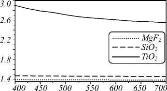
Wavelength, nm
Extinction Coefficient, к
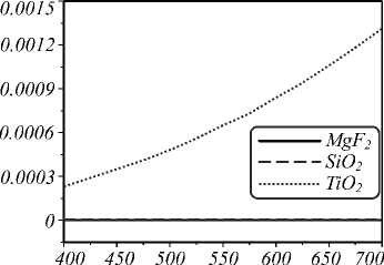
Wavelength, nm
Fig. 2. Refractive index(a) and extinction coefficient(b) of SiO 2 , MgF 2 and TiO 2
-
B. Filter 1: FP filter design based on TiO 2 / MgF 2
TiO 2 and MgF 2 are chosen as high and low refractive index materials, respectively. As mentioned in section A, the choice of materials is made on the basis of low absorption and high index contrast in the wavelengths of interest. The design was optimized to 97 % transmission at 511 nm and narrow FWHM of 2 nm. The design comprised of 19 layers with thickness of 1457 nm, Fig. 3.
The optimized thickness of each layer is shown in Table 1. The filter design comprises of two DBRs having 9
350 400 450 500 550 600 650 700 Wavelength, nm
layers each and a spacer (layer no. 10) is sandwiched between them. The layers thickness is automatically optimized by using needle synthesis method.
Transmission, %
Fig. 3. FP filter with two DBRs of TiO 2 / MgF 2 with 19 layers, 97 % transmission at 511 nm and 2 nm FWHM
Table 1. Layer thickness of TiO 2 / MgF 2 based FP filter with a passband of 511 nm
|
Layer no. |
Materials |
Thickness (nm) |
|
1 |
TiO 2 |
99 |
|
2 |
MgF 2 |
85 |
|
3 |
TiO 2 |
53 |
|
4 |
MgF 2 |
92 |
|
5 |
TiO 2 |
53 |
|
6 |
MgF 2 |
94 |
|
7 |
TiO 2 |
53 |
|
8 |
MgF 2 |
96 |
|
9 |
TiO 2 |
53 |
|
10 |
MgF 2 |
98 |
|
11 |
TiO 2 |
118 |
|
12 |
MgF 2 |
61 |
|
13 |
TiO 2 |
43 |
|
14 |
MgF 2 |
110 |
|
15 |
TiO 2 |
53 |
|
16 |
MgF 2 |
98 |
|
17 |
TiO 2 |
52 |
|
18 |
MgF 2 |
94 |
19 TiO 2 53
-
C. Filter 2:FP filter design based on TiO 2 / SiO 2
TiO 2 and SiO 2 are chosen as high and low refractive index materials, respectively. The choice of materials is made on the basis of low absorption and high index contrast in the wavelengths of interest, Fig. 2. The design was optimized to 96 % transmission at 511 nm and narrow FWHM of 2 nm, total layers increased to 21 and thickness of 1351 nm, Fig. 4.
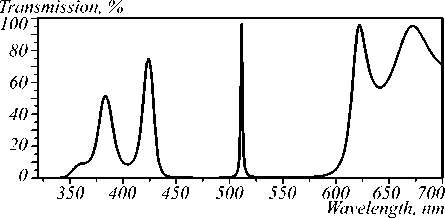
Fig. 4. FP filter with two DBRs of TiO 2 / SiO 2 with 21 layers, 96 % transmission at 511 nm and 2 nm FWHM
The optimized thickness of each layer is shown in Table 2. In this filter design, FP comprises of two DBRs having 11 and 9 layers each and a spacer (layer no. 12) is sandwiched between them. We obtained same results with two DBRs of 11 layers each but in order to reduce the number of layers. We have selected asymmetric DBRs; this can help in reducing the cost of fabrication. The layers thickness is automatically optimized by using needle synthesis method.
Table 2. Layer thickness of TiO 2 /SiO 2 based FP filter with a passband of 511 nm.
|
Layer no. |
Materials |
Thickness (nm) |
|
1 |
TiO 2 |
54 |
|
2 |
SiO 2 |
86 |
|
3 |
TiO 2 |
54 |
|
4 |
SiO 2 |
86 |
|
5 |
TiO 2 |
54 |
|
6 |
SiO 2 |
86 |
|
7 |
TiO 2 |
54 |
|
8 |
SiO 2 |
88 |
|
9 |
TiO 2 |
57 |
|
10 |
SiO 2 |
44 |
|
11 |
TiO 2 |
42 |
|
12 |
SiO 2 |
46 |
|
13 |
TiO 2 |
39 |
|
14 |
SiO 2 |
84 |
|
15 |
TiO 2 |
55 |
|
16 |
SiO 2 |
86 |
|
17 |
TiO 2 |
54 |
|
18 |
SiO 2 |
86 |
|
19 |
TiO 2 |
54 |
|
20 |
SiO 2 |
86 |
|
21 |
TiO 2 |
54 |
-
D. Filter 3: Bandpass filter design based on TiO 2 /SiO 2
In order to obtain the desired specific wavelength in full visible region, a bandpass filter was designed based on DBRs. The design approach was based on (2HL)n layer configuration with central wavelength at 511 nm [9], [10], [11]. TiO 2 and SiO 2 are chosen as high and low refractive index materials, respectively. The design was optimized using needle synthesis methods; total thickness of bandpass after optimization is 2361 nm with 29 layers. Banspass filter has an average transmission of 95 %, minimum and maximum transmission of 94 % and 96 % within passband, respectively.
The combined effect of filter 1 (FP filter TiO 2 / MgF 2 ) with filter 3 (Bandpass filter TiO 2 / SiO 2 ) and combined effect of filter 2 (FP Filter TiO 2 / SiO 2 ) with filter 3 fulfill the requirement of fluorescence microscopic imaging and can transmit the excitation wavelength while suppressing all the wavelengths outside the stopband of the FP DBRs. The optimized layer thicknesses of bandpass filter is shown in table 3.
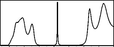
The transmission spectrum of the resulting filters (filter 1 + filter 3) is shown in fig. 5. It is well noted that the overall transmission spectra in the visible range of the spectrum shows a characteristic peak at 511 nm with a maximum of 96 % and a small peak at 433 nm. FP filter and pass band filter can be fabricated on same substrate in the form of single optical element with high characteristic peak at 511 nm.
Table 3. Layer thickness of bandpass filter based on TiO 2 / SiO 2
|
Layer no. |
Materials |
Thickness (nm) |
|
1 |
TiO 2 |
126 |
|
2 |
SiO 2 |
54 |
|
3 |
TiO 2 |
46 |
|
4 |
SiO 2 |
59 |
|
5 |
TiO 2 |
45 |
|
6 |
SiO 2 |
55 |
|
7 |
TiO 2 |
36 |
|
8 |
SiO 2 |
71 |
|
9 |
TiO 2 |
44 |
|
10 |
SiO 2 |
78 |
|
11 |
TiO 2 |
129 |
|
12 |
SiO 2 |
47 |
|
13 |
TiO 2 |
85 |
|
14 |
SiO 2 |
37 |
|
15 |
TiO 2 |
141 |
|
16 |
SiO 2 |
18 |
|
17 |
TiO 2 |
180 |
|
18 |
SiO 2 |
103 |
|
19 |
TiO 2 |
85 |
|
20 |
SiO 2 |
111 |
|
21 |
TiO 2 |
74 |
|
22 |
SiO 2 |
95 |
|
23 |
TiO 2 |
77 |
|
24 |
SiO 2 |
112 |
|
25 |
TiO 2 |
76 |
|
26 |
SiO 2 |
107 |
|
27 |
TiO 2 |
74 |
|
28 |
SiO 2 |
100 |
|
29 |
TiO 2 |
97 |
Resulting spectrum ofFPfilter 1 and bandpass filter
Transmission, %
100 A-----------------------------------------------
80 7 Resulting spectrum
601 ofFPfilter 1
: and bandpass filter
-
40-. /
20-, I
ОД—i-- 1» r11 —l| * r-^—i ' 1—r-M^=
350 400 450 500 550 600 650 700
Wavelength, nm
Fig. 5. Resulting spectrum of filter 1 and filter 3 with 3 % transmission outside passband
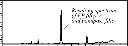
The transmission spectrum of the combined filters (filter 2 + filter 3) is shown in fig. 6. It can be seen that the overall transmission spectra in the visible range of the spectrum shows a characteristic peak at 511 nm with a maximum of 96 %. FP filter and pass band filter can be fabricated on same substrate in the form of single optical element with high characteristic peak at 511 nm.
Conclusions
In this work, we presented two FP filter designs based on TiO 2 / SiO 2 and TiO 2 / MgF 2 combined with two bandpass filters based on TiO 2 / SiO 2 . These filters provide a peak transmission of 96 % and 97 % at 511 nm. By combining two DBRs with FP filter, the transmission outside the passband reduced to 3 %. The combined effect of filters fulfils the requirement of fluorescence microscopic imaging and can transmit the excitation wavelength while suppressing all the wavelengths outside the stopband of the FP DBRs.
Transmission, %
О
300 350 400 450 500 550 600 650 700 750
Wavelength, пт
Fig. 6. Resulting spectrum of filter 2 and filter 3 with 3 % transmission outside passband
Список литературы Modelling of multilayer dielectric filters based on TIO2 / SIO2 and TIO2 / MgF2 for fluorescence microscopy imaging
- Macleod, H.A. Thin-film optical filters/H.A. Macleod. -Boca Raton, FL: CRC Press, 2010. -ISBN 978-1-4200-7302-7.
- Kazanskiy, N.L. Harnessing the guided-mode resonance to design nanooptical transmission spectral filters/N.L. Kazanskiy, P.G. Serafimovich, S.N. Khonina//Optical Memory and Neural Networks (Information Optics). -2010. -Vol. 19(4). -P. 318-324.
- Kazanskiy, N.L. Simulation of spectral filters used in hyperspectrometer by decomposition on vector Bessel modes/N.L. Kazanskiy, S.I. Kharitonov, S.N. Khonina, S.G. Volotovskiy//Proceedings of SPIE. -2014. -Vol. 9533. -95330L. -DOI: 10.1117/12.2183429.
- Asghar, M.H. Modeling thin film multilayer broad-band-pass filters in visible spectrum/M.H. Asghar, M.B. Khan, S. Naseem//Czechoslovak Journal of Physics. -2003. -Vol. 53(12). -P. 1209-1217. - DOI: 10.1023/B:CJOP.0000010585.26194.eb
- Ramanujam, N. Fluorescence spectroscopy of neoplastic and non-neoplastic tissues/N. Ramanujam//Neoplasia. -2000. -Vol. 2(1-2). -P. 89-117.
- Grazyna, P. Noninvasive two-photon fluorescence microscopy imaging of mouse retina and RPE through the pupil of the eye/P. Grazyna, D. Zhiqian, G. Marcin, J.H. Jennifer, R.W. David, S.A. Nathan, P. Kryzsztof//Nature Medicine. -2014. -Vol. 20(7). -P. 785-789. - DOI: 10.1038/nm.3590
- Spiess, E. Two-photon excitation and emission spectra of the green fluorescent protein variants ECFP, EGFP and EYFP/E. Spiess, F. Bestvater, A. Heckel-Pompey, K. Toth, M. Hacker, G. Stobrawa, T. Feurer, C. Wotzlaw, U. Berchner-Pfannschmidt, T. Porwol, T. Acker//Journal of Microscopy. -2005. -Vol. 217(3). -P. 200-204. - DOI: 10.1111/j.1365-2818.2005.01437.x
- Larouche, S. OpenFilters: open-source software for the design, optimization, and synthesis of optical filters/S. Larouche, L. Martinu//Applied Optics. -2008. -Vol. 47(13). -P. C219-C230.
- Asghar, M.H. Wide bandpass optical filters with TiO2 and Ta2O5/M.H. Asghar, M. Shoaib, F. Placido, S. Naseem//Central European Journal of Physics. -2008. -Vol. 6(4). -P. 853-863. - DOI: 10.2478/s11534-008-0104-3
- Asghar, M.H. Complex optical filter prepared by sputter deposition/M.H. Asghar, M. Shoaib, Z.M. Khan, F. Placido, S. Naseem, M. Mehmood//The European Physical Journal Applied Physics. -2010. -Vol. 49(2). -20501. - DOI: 10.1051/epjap/2009205
- Habib, M. Simulation of Near Infrared Interference Bandpass Filters for Spectropcscopic Applications/M. Habib, A. Ullah//International conference on Computing, Electronic and Electrical Engineering. -2016. -P. 234-238. - DOI: 10.1109/ICECUBE.2016.7495230
