Modified Digital Filtering Algorithm to Enhance Perceptual Evaluation of Speech Quality (PESQ) of VoIP
 of VoIP")
Author: Imran Ghous, Tahir Muhammad, Habibullah Jamal
Journal: International Journal of Image, Graphics and Signal Processing(IJIGSP) @ijigsp
Article in issue: 4 vol.5, 2013.
Free access
Speech quality of VoIP system is degraded due different network layer problems such as packet loss delay and jitter and external noise. This paper compares the quality of speech signal that is implemented on digital signal processor using G.729 audio data compression algorithm with the ITU-T G.711 PCM coder implemented using modified digital filtering algorithm. PESQ (ITU-T P.862, Perceptual Evaluation of Speech Quality) is used to evaluate the performance. The results indicate that our proposed architecture has better performance.
Noise Reduction, G.711, VoIP Implementation
Short address: https://sciup.org/15012695
IDR: 15012695
Text of the scientific article Modified Digital Filtering Algorithm to Enhance Perceptual Evaluation of Speech Quality (PESQ) of VoIP
Now-a-days speech coding is widely used and it is an important topic in research. These techniques are mainly used to compress the speech for storage and transmission purpose but the goal here is that the quality of decompressed signal has to be good. The component which is used to compress a speech signal is called encoder and the component which decompresses it is called decoder and both these components are collectively called speech codec’s.
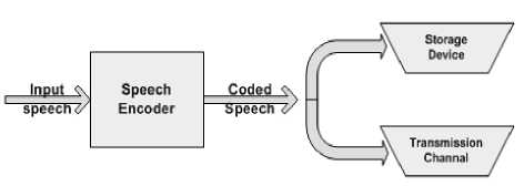
Figure 1. Encoder
Decodedx Speech
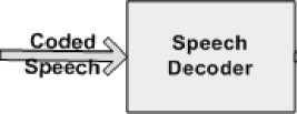
Figure 2. Encoder
Figure 1 depicts the block diagram of the encoder. After encoding the input speech signal, resultant encoded signal is either used for the transmission purpose through the channel or it may be used for the storage purpose. Block diagram of decoder is depicted in figure 2. The encoded speech signal after transmission through the channel needs to be decoded.
Slight communication delay is observed when a speech coder processes a signal. The speech coders perform their functionality in the form of the blocks of the samples. This delay associated with the codec’s may vary from 1 to 500 ms . Excessive delays are associated with the video telephony systems. Complexity is measured basically in the terms of operations performed and memory locations. The problems of more power consumption and higher delays are associated with the complexity. Now-a-days due to advancements in the design technology the speech codec’s can be implemented with the acceptable delays and less power consumption [1].
Speech coders may be classified into three categories which are Source coders, Waveform coder and Hybrid coder. The least complex coders are Waveform coders. They tend to reform the signal which is closer to the input and they are independent of the input. The two approaches which are used by the simplest coders are quantization and sampling.
On this principle the Pulse Code Modulation (PCM) works. At the reduced bit rate the good sample quality of the reconstruction signal is provided by the Logarithmic Quantization. Bit rate of 64 kbps is obtained with this type of coder [2-3].
Another type of Waveform coder is Differential Pulse Code Modulation (DPCM) coder. The difference between the input signal and predicted signal is coded in this type of the coder. Thus bits which are required for coding are reduced. Bit rate of 32 kbps is used by this type of the coder. When Waveform coding is done in the frequency domain, a signal is split into different frequency bands and each of these separated bands are transmitted separately [4].
Sub-band Coding and Adoptive Transform Coding are the examples of frequency domain Waveform Coding. These coding schemes are more tedious than those of the time domain coding schemes because it is compulsory to divide the signal into the sub-bands during filtering. Reconstructed signal of such a coder loses its naturalness. In the reconstructed signal a synthetic fed is usually observed but this type of coder is used where the bit rate is main priority not the naturalness of speech [5].
If we want a compromise between the Source coders and Waveform coders in terms of both bit rate and how they code signals then we can use hybrid coders. Code Excited Linear Predictive (CELP) coder is the example of Hybrid coder. It is analysis-by-analysis coder. This coder applies the linear prediction and residual signal is quantized by it. The quantized parameters which are transmitted are residual signal and linear prediction filter. The residual signal excites the synthesis filter in such a way that it reduces the error and matches the input signal as close as possible [6].
Most common voice codec’s that are used now-a-days are G.711, G.729, G.722 and G.723. We shall take into consideration the two codec’s G.729 and G.711. In G.729 coder the original and locally decoded signal are compared and on the basis of the coder parameters the mean square error between two signals is minimized. The coder operates with a band limited signal sampled at 8000 Hz. 16-b linear PCM is used to denote the input and the output. This type of coder operates with the 10 ms frames. And it uses 5 ms for Linear Prediction (LP) analysis so; the delay of 16 ms is observed in overall algorithm. Each of these coders use the specific type of quantization [7].
Quantizers are of many kinds but we have to select the best according to our application. Some well known are Simple-Uniform-Quantizers, Pdf-optimized-Quantizers and the Logarithmic-Quantizers. For speech signals, the Uniform and Pdf-Optimized-Quantizers are not adequate SNR-wise. These two Quantizers are very sensitive to changes of the signal variance but the variance of speech signals varies a lot with time. On the other hand, a Logarithmic quantizer SNR does not depend too much on the signal variance. The Logarithmic quantizer is therefore a better selection for speech signals that is why we have used G.711 quantizer. ITU-T G.711 is a very popular narrow-band high-bit rate coder.
The input and output of the coder are sampled at 8000 and each sample is encoded with 8 bits due to which the bit rate of coder is 64 kbps. The two encoding laws which are supported by G.711 are known as A-law and µ-law. Consequently the quantization error is minimum in G.711 as compared to those which use fixed step size [8].
Different types of parameters influence the performance of the speech coder. At the cost of reduction in bit rate speech signal quality is improved by speech coder. The quality of the speech signal is decoded on the basis of the MOS scale. In MOS scale a comparison is done between the original signal and degenerated signal on the basis of another scale called perceptual evaluation of speech quality (PESQ). So, the basic purpose of PESQ is to measure the quality of sound. As the MOS scale requires a large number of listeners, this requirement is eliminated in case of PESQ scale while all other features are similar to that of MOS scale [16].
The quality of our decoded speech signal is degraded due to the different noises such as environmental noise and quantization noise. The quantization noise is property of the coder and the environmental noise is available at the encoder and it is undesired. So, both these noises should be filtered for the improvement in the quality of the resultant signal. Typically the environmental noise is estimated during non speech intervals and it is assumed that the talker is in the same environment when he/she resumes talking. Then the estimated noise can be reduced during speech intervals.
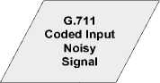
In this paper we have used the modified digital filtering algorithm for the improvement in the quality of G.711 coded noisy signals.
The remaining section of this paper is devised as follows. In section II , background is described to efficiently implement the proposed algorithm. Section Ш , describes the proposed algorithm in detail. After that, comparison of the proposed algorithm is discussed in section W , and we draw our conclusion in the last section.
-
II. BACKGROUND
Noise reduction techniques are used in many ways by VoIP. When voice signals are encoded, packetized, and transmitted over across a VoIP network, other network deportments and handicaps come into action that may not be efficiently handled by the telephony noise diminution and nullification methods. Any interfering signal is called noise but in case of VoIP we can redefine the noise as any undesirable characteristics which degrade the signal of interest [9]. The quality of VoIP signal is affected by different types of noises. The factors which influence the quality of speech signal are mentioned below.
-
A. Distortion and Noise Yields
-
1) Telephony Impairment: VoIP networks have to be interfaced in some aspects with PSTN. Which means as the result of this impairment the quality of the VoIP signal is affected.
-
2) Subtractive and Additive Distortion: VoIP systems are wholly affected by both these types of distortions. Additive distortion is resultant of background noise and circuit noise while the subtractive noise is resultant of severe attenuation and fugacious signal loss. Distortions are substantial in VoIP applications due to codec’s. Before the encoding process noise affects the VoIP signal produces undesirable effects. It depends upon the type of the encoding whether noise possesses frequency components within the voice band or not [10].
-
3) Time-Variance and Non-Linearity: Time variance and linearity conditions are major deviations between PSTN and VoIP voice channels. The property of time invariance is associated with a PSTN channel and the property of time variance and linearity are associated with a VoIP channel. Due to this condition the noise reduction in VoIP channel is quite challenging.
-
4) Delay and Audio Variance (Jitter): The time taken by a signal to travel from talker to listener is called End-to-end delay. This end to end delay degrades the quality of sound without affecting actual voice signal [10].
-
5) IP Packet Loss: IP stands for internet protocol that is considered as undependable networking protocol. In its basic form the IP offers no guarantees of error recovery, reliability and flow control etc. Due to which the packets may be delivered in duplicates or in out of order [11].
-
6) Environmental Noise: Environmental noise comes from the surroundings of the conversation parties. The noise can disturb the conversation in many ways. It could for example be so loud that the portion of the conversation becomes covered by it. The listener would not be able to hear the information given by the speaker clearly and this could lead to miscommunication. The noise could also be a distraction for the listener.
-
7) Quantization Noise: The coding noise tend to make the speech less periodic: the speech formants and speech harmonics are less prominent after coding. The filtering attempts to reestablish the prominence of formants and harmonics.
-
B. Processing of VoIP
The quality of VoIP signal is not only affected by distortion, delays, environmental noise, packet loss and jitter but it is also affected by the processes that are related to VoIP equipments and VoIP gateways. So a codec under its optimum conditions will give us best quality of noise unless it is affected worse conditions such as packet loss and background noise.
Prior to the transmission of VoIP signals over an IP network the codec’s packetize and digitize the voice signals. Some codec’s help in saving the network bandwidth by compressing the voice signals. Voice codec’s can be implemented either by using software or hardware. The signal distortion is directly proportional to the increase in jitter or packet loss but it depends upon the packet loss type or location that whether the perceived quality of signal is affected by the distortion or not [12].
So all these factors affect the quality of a voice signal to great extent and ultimately the voice signal that we shall hear at the receiver side will possess the effects of all these internal and external noises. The receiver may not understand the actual message in the presence of all these noises. So these noises have to be filtered so that our original message can be heard clearly by the user.
For this purpose we have proposed an algorithm which can improve the quality of degraded VoIP signal to a greater extent. The output signal that is obtained by using this algorithm has better results than the speech signal that was obtained by using previously implemented technique [13].
In our proposed architecture we have used the noisy signal as an input and then we have encoded that noisy signal. Then the encoded signal is passed through the modified digital filtering algorithm block which uses the Hanning window to remove the unwanted components from our input signal. Thus ultimately our enhanced signal is obtained at the output. The quality of the enhanced signal is verified using PESQ which shows the significant improvement in the quality of speech signal.
The next section shows the detailed sketch of our proposed architecture of algorithm and also presents the significant explanation of our modified digital filtering algorithm block.
-
III. PROPOSED ARCHITECTURE
-
A. Proposed Architecture of Algorithm
The speech signal is taken as an input from [14]. The external noise gets added into input VoIP signal. Using G.711 encoder the resultant noisy speech signal is encoded into VOIP frames. The network configurations were inserted into VoIP frames by using simple Gilbert model. If there is an “Error” state then in that case a VoIP packet is dropped otherwise it is retained. The resulting stream of frames that are available at the G.711 encoder output are then decoded using G.711 decoder and then the resultant decoded signal is filtered for the noise using modified digital filtering algorithm.
Figure 3 shows the proposed architecture of the given algorithm. There are two types of compression algorithms which are defined by G.711. One is called
µ-law algorithm and another is called A-law algorithm. The µ-law algorithm encodes 14-bit signed linear PCM samples to Logarithmic 8-bit samples and the A-law algorithm encodes 13-bit signed linear PCM samples to 8-bit Logarithmic scale. We shall use µ-law algorithm in our proposed architecture.
In case of µ-law algorithm for each 14 bit linear code there is a specific compressed code. The µ-law algorithm actually increases the magnitude of 14-bit signed by 32 and then converts it into 8-bit number.
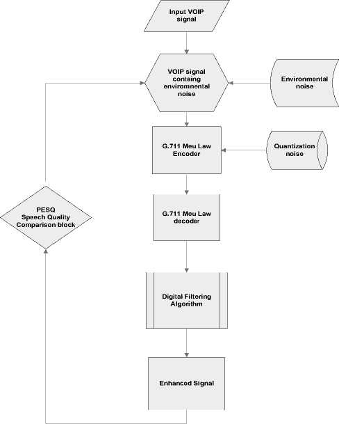
Figure 3. Proposed Architecture of Algorithm
-
B. Noise Filtering
Window based filter design method is used to improve the quality of the degraded VoIP signal because these types of filters are inherently stable , have linear phase, great flexibility in shaping the magnitude response and are easy to implement.
Z domain is used to represent the transfer function of the FIR filters. This is also called all-zero filter because the zeros in z-plane help in finding frequency response magnitude characteristics. The N-point FIR filter in z domain is given by
N - 1 - n
H ( z ) = 2 h ( n ) z (1)
n = 0
The frequency response h ( w ) corresponding to the unit impulse response h ( n ) in window based method can be found by following equations
- n
hd (n) =ЪГ^ hd (^)ejwndw
П
X
hd (w) = 2 hd (n)ej n=-x
The above relation gives the value of h ( n ) in infinite duration. So this infinite duration needed to be cut short to a point n = M - 1 in order to yield the FIR filter of length M.
This finite limitation of h ( n )to length M - Ihas the same effect as we multiply h ( n ) to rectangular window. The rectangular is defined as
1 0 < n < M - 1
w ( n ) =
0 otherwise
The unit impulse response of desired FIR filter is given as h (n) = hd (n) w (n)
= hd ( n ) 0 < n < M - 1
= 0 otherwise
The value of w ( n ) for Hanning Window is given by following equation
2 p ( n + 1) N + 1
, , 0.5-0.5cosl w (n) =
n = 0,.1...., N - 1
0 otherwise
Figure 4 shows the block diagram of modified digital filtering algorithm block which shows how noise is filtered from the signal that is available at the output of the decoder. The signal passing through this block gets filtered and output signal which is obtained is enhanced signal.
Window based FIR filtering is more simple, beneficial and fruitful as compared to other filtering methods and these are easy to use. The main reason beyond preferring this type of filtering methods is that these methods possess the set of well defined equation for the computation of the window coefficients. The proposed FIR filter is designed in MATLAB SIMULINK [15].
Figure 4 shows the block diagram of modified digital filtering algorithm. Input is noisy signal whose samples after passing through Data Buffering and Windowing block are sent to Voice Activity Detection (VAD) Block. The first Stage in VAD is noise reduction stage and on the basis of the classification rule the speech and nonspeech signals are estimated in VAD. Feedback in VAD improves the performance in case of non-stationary noisy signals and then noise cancellation block estimates the remaining noise in the input signal and then removes it. After that Add and Overlap Block reorders the multidimensional input signals and ultimately enhanced signal is obtained.
-
IV. COMPARISON
In this section we shall compare our results obtained by the proposed architecture of algorithm with results of the technique involving G.729 coder [13]. The figure 6 depicts the plot of the input noisy signal and figure 7 depicts the amplitude spectrum of this noisy signal.
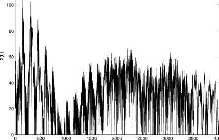
Similarly figure 8 depicts the amplitude spectrum of noisy signal and figure 9 depicts the enhanced signal.
By comparing the figure 6 and figure 8 a clear distinction can be made between Enhanced signal and the input noisy signal.
If we compare the amplitude spectrum of both signals we can see that unwanted frequency components which were associated with noise are not appearing in the amplitude spectrum of filtered signal. While those unwanted frequency components can be observed in the amplitude spectrum of the noisy signal.
Data Buffering and Windowing
VAD
FFT Block
-
V. CONCLUSION AND FUTURE WORK
By analyzing the spectrum of both input noisy signal and output enhanced signal we can observe that the filter is designed in such a way that it efficiently improves the quality of the input noisy signal. The PESQ comparison of both techniques is shown figure 5 which indicates that quality of speech signal obtained by our proposed architecture of algorithm is better than that of architecture used in [13]. PESQ value of the speech signal that is obtained by using our architecture of algorithm is 2.5507 and by using previous architecture its value was 2.4.
In future this work can also be implemented using ITU-T G.711.1 that is extension of G.711 codec and results can be compared with both of these algorithms.
Noise Cancellation Block
Bias Removal
Half Wave Rectification
Rseidual Noise Reduction
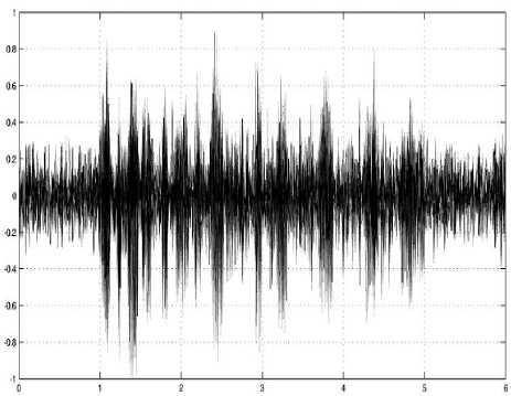
Figure 6. Input Noisy VoIP Signal
IFFT
Add and Overlap
I
Filtered Output Signal
Figure 4. Modified Digital Filtering Algorithm
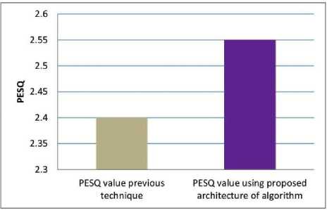
Figure 5. PESQ Comparison
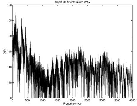
Figure 7. Amplitude Spectrum of Input Noisy Signal
Amplitude Spectrum of '.WAV
Frequency (Hz)
Figure 8. Amplitude Spectrum of Output Enhanced Signal
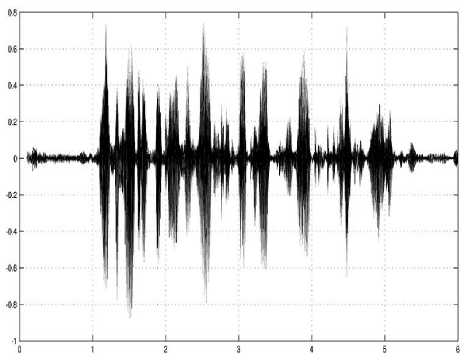
Figure 9. Filtered Output Enhanced Signal
References Modified Digital Filtering Algorithm to Enhance Perceptual Evaluation of Speech Quality (PESQ) of VoIP
- D. Collins, Carrier Grade Voice Over IP. San Francisco: McGraw-Hill, 2001.
- N. Katugampala and A. Kondoz, "A hybrid coder based on a new phase model for synchronization between harmonic and waveform coded segments," in Acoustics, Speech, and Signal Processing, 2001. Proceedings. (ICASSP '01). 2001 IEEE International Conference on, 2001, pp. 685-688 vol.2.
- G. H. Hakonsen and T. A. Ramstad, "On Losses of Performance in a Joint Source Channel Coder," in Signal Processing Symposium, 2006. NORSIG 2006. Proceedings of the 7th Nordic, 2006, pp. 278-281.
- J. C. Bellamy. (2000). Digital Telephony.
- T. Painter and A. Spanias, "Perceptual coding of digital audio," Proceedings of the IEEE, vol. 88, pp. 451-515, 2000.
- S. M. Tsai and J. F. Yang, "Efficient algebraic code-excited linear predictive codebook search," Vision, Image and Signal Processing, IEE Proceedings -, vol. 153, pp. 761-768, 2006.
- C. W. Therdpong Daengsi, Apiruck Preechayasomboon, Saowanit Sukparungsee, "Speech Quality Assessment of VoIP: G.711 VS G.722 Based on Interview Tests with Thai Users," MECS, vol. 4, pp. 19-25, March 2012.
- T. Daengsi, et al., "A study of VoIP quality evaluation: User perception of voice quality from G.729, G.711 and G.722," in Consumer Communications and Networking Conference (CCNC), 2012 IEEE, 2012, pp. 342-345.
- M. Konate and P. Kabal, "Quantization noise estimation for log-PCM," in Electrical and Computer Engineering (CCECE), 2011 24th Canadian Conference on, 2011, pp. 001337-001341.
- S. Paulsen, et al., "Influence of the jitter buffer on the quality of service VoIP," in Ultra Modern Telecommunications and Control Systems and Workshops (ICUMT), 2011 3rd International Congress on, 2011, pp. 1-5.
- D. a. M. Minolli, E, Delivering Voice Over IP Networks. New York: John Wiley & Sons, 1998.
- R. J. B. a. R. Reynolds, A. W, "Quality VoIP - an engineering challenge " BT Technology Journal, vol. Vol.19 No.2, April 2001.
- H. P. Singh, et al., "Processing of VoIP Signal Using TMS320C6713 in Digital Domain," in Computer Engineering and Applications (ICCEA), 2010 Second International Conference on, 2010, pp. 606-610.
- http://www.voiptroubleshooter.com/open_speech/. Open Speech Repository.
- http://www.mathworks.com/help/dsp/ref/g711codec.html. MathWorks.
- ITU-T Recommendation P.862," Perceptual evaluation of speech quality (PESQ), an objective method for end to end speech quality assessment of narrow band telephone networks and speech codecs, " Feb. 2001.
