Motion Estimation for Omnidirectional Images using the Adapted Block-Matching

Author: ALOUACHE Djamal, AMEUR Zohra, KACHI Djemaa
Journal: International Journal of Image, Graphics and Signal Processing(IJIGSP) @ijigsp
Article in issue: 9 vol.6, 2014.
Free access
The Block-Matching (BM) method for motion estimation in most video coding is largely discussed in the case of perspective images. The omnidirectional cameras provide images with large field of view. These images contain global information about motion and permit to remove the ambiguity present with little camera motion in perspective case. Nevertheless, these images contain significant radial distortions. The Block-Matching in these catadioptric images is not a resolved problem, and still a challenging research field. A rectangular block representing the neighborhood in BM of a point and used in the perspective images is not appropriate for catadioptric cameras. The work presented in this article concerns the local motion estimation in catadioptric videos with the Adapted Block-Matching (ABM). The ABM based on an adapted neighborhood, the local motion estimation allows successful compensation prediction in catadioptric images. The Adapted Block-Matching is obtained from the equivalence between the omnidirectional image and the projection of scene points on a unit sphere.
Catadioptric images, adapted neighborhood, motion estimation, Adapted Block-Matching
Short address: https://sciup.org/15013406
IDR: 15013406
Text of the scientific article Motion Estimation for Omnidirectional Images using the Adapted Block-Matching
Block-Matching methods are the most used in practice for motion estimation [1], [2]. They are found in almost all Modern video coding standards (H.261, MPEG-1, MPEG-2-4…). In the methods of the Block- Matching, two rectangular blocks are mapped according to the information distribution of their pixels.
The omnidirectional image has a non-homogeneous resolution. A rectangular block representing the neighborhood in BM of a point used in perspective images is not appropriate for catadioptric cameras. The Block-Matching method cannot be applied directly on catadioptric images because it necessarily leads to errors. Some authors seek to adapt the classical methods (applied to perspective images) in the omnidirectional images, by seeking the adequate neighborhoods [9], [10]. Tosic et al [3] and Bogdanova et al [4] propose to use BlockMatching method in terms of spherical coordinates. The omnidirectional image is projected on the sphere of equivalence and the Spherical Block Matching (SBM) is developed to estimate motion in catadioptric sequences. To estimate the motion, the algorithm simply puts in correspondence two solid angles between two spherical images. Other researchers have also used Spherical Block Matching in catadioptric videos compression application [5], [6]. For example, in article [6] the authors used the Spherical Block Matching in loop motion compensation in the Slepian-Wolf decoder. The correlation between images is then assessed by estimating the motion between the two spherical images.
Because of interpolation noise introduced by the projection on the sphere some authors have underlined the incompatibility of treatments on the sphere (see for example [7], [8] and [9]). The objective of this paper is therefore to propose a direct adaptation of the classical Block-Matching in the omnidirectional images from the definition of a neighborhood system taking distortions into account. The remainder of this paper is organized as follows: in section 2, we present classical BlockMatching. In section 3 the catadioptric vision and the equivalence projection are presented. Section 4 describes, our approach to estimate motion using the BlockMatching with appropriate neighborhood. In section 5, the experimental evaluation is given and comparative measurements are discussed.
-
II. Classical Block-Matching
Classical Block-Matching computes the optical flow on pixel p(x,y) considering that the motion is constant in a fixed rectangular neighborhood. Two blocks B(x,y,t) and B’(x,y,t+1) are correlated according to the information distribution of their pixels in two successive images I(x,y,t) and I(x,y,t+1). Let us note V= (vx, vy) the vector parameters of motion, B and B’ the rectangular neighborhood of the point in position p(x,y) in successive images and W(x,y) the search window as depicted in Fig. 1.
The Block-Matching method consists to estimate velocity vector V(x,y) at the neighborhood B(x,y) in search window W(x,y), generally the best candidate block is selected with the minimum SAD error (1):
V ( X , y ) = arg min £ I B ( X , y , t ) - B ' ( X + V x , y + V y , t + 1) | (1) v x , v y W ( x , y )
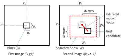
Fig. 1.Classical Block Matching
-
III. Catadioptric Vision
Catadioptric vision consists in associating a convex mirror with a camera whose optical axis is coincident with the axis of revolution of the mirror. Many authors have studied in their works equivalence between a catadioptric projection and stereographic projection [10, 11].
Geyer and Daniilidis have introduced a unifying theory for all central catadioptric sensors [11]. They proved that central catadioptric projection is equivalent to a central projection on a virtual sphere followed by projection from the sphere to the retina. This second projection depends on the shape of the mirror.
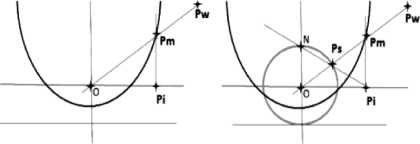
Fig. 2.Equivalence between the catadioptric projection and the two-step mapping via the unit sphere
Firstly the 3D point is projected in sphere from the center of sphere “O”; the second step consists in projecting point Ps on the sphere to the image plane from point “N” placed on the optical axis (Fig. 2). These projection points are obtained by calibrating the sensor.
Let (Xs,Ys,Zs), Cartesian coordinate’s point Ps and (θ, φ) the equivalent spherical coordinates.
sin 0 cos в
P s ( X s , Y s , Z s ) = ^
sin 0 sin ^
cos0
With ф e [0, 2n [, longitude angle and 9 e [0, n/2], latitude angle, the stereographic projection of Ps on the image plane yields point P i (x, y) given by:
X = Xs/(1 - Zs) y = Ys/(1 - Zs)
By combining Equations (4) and (5) we obtain the spherical coordinates of point P i (x (θ, φ), y (θ, φ))
. 0 .x =cot cosф
y = cot — sin ф
-
IV. Adapted Block-Matching
-
A. Proposed Neighborhood for catadioptric images
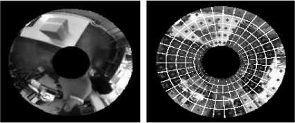
In Demonceaux et al [7] the adapted neighborhood has been used for segmentation of omnidirectional images using Markov fields. The adapted neighbourhood is obtained from the equivalence between the omnidirectional image and the projection of scene points on a sphere as defined in Fig. 3. Radgui et al [8], [12] propose to use the spherical neighborhood in order to adapt the Lucas-Kanade method to estimate the optical flow in paracatadioptric images. The method proposed by Radgui et al [8], [12] allows a good estimate of the optical flow in the case of small displacements of the catadioptric camera. We propose, in this paper, to use the neighbourhood initially proposed in [7]. The adapted neighborhood noted ϑ (x, y) at point (x,y), is defined as follows :
(X, y) e^x, y ^ 0 - °|< d0 et V - ф\< dV (5)
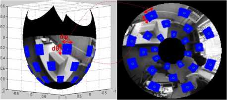
Fig. 3.Adapted neighborhood in omnidirectional image
Where θ and φ are the spherical coordinates of pixel (x ,y ). Constants dθ and dφ define the size of adapted neighborhood. In the proposed approach, (dθ B , dφ B ) and (dθ W , dφ W ) define respectively the size of block B x,y and search window W x,y . With the neighborhood in (5) block B x,y and search window W x,y depend on the position of pixels in the omnidirectional image as depicted in Fig. 3. In the following section, we describe the Block-Matching method which uses this kind of neighborhood.
-
B. Adapted neighborhood used in Block-Matching
The Adapted Block-Matching puts in correspondence two adapted blocks between two successive omnidirectional images. Adapted search window Wx,y and adapted block Bx,y are obtained from equivalence between points of the omnidirectional image and points of equivalent sphere as depicted in Fig. 3.
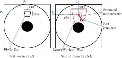
Fig. 4.Adapted Block Matching
First, the Algorithm consists in projecting two successive omnidirectional images on the unit sphere by using inverse stereographic projection and in addition divide first spherical Image I(θ,φ,t) into uniform solid angles of size dθB× dφB that form blocks with a constant motion (See Fig. 5). The second step is to define the neighborhood B x,y in omnidirectional image I(x,y,t) using stereographic projection as described in (6). The last step is to find best block B’ x,y belonging in target adapted search window dθ W ×dφ W on second omnidirectional image I(x,y,t+1) as depicted in Fig. 4.
(a) (b)
Fig.5. Adapted Block in Omnidirectional Image (a) Reference Image (t) (b) Dividing in no overlap blocks
Adapted block of point p (x i ,y i ) noted B x,y is defined as follows:
(xi, yi) e Bx, y ° |6 - @i\< d6B et |ф - ф\< d^B(6)
Blocks B x,y and B’ x,y minimizing the well known Sum of Absolute Differences (SAD) are used to compute the motion vector ( dx,dy ) :
SAD (x,y) = £| B,.„ -B',+„„+dr,M|
Wx , y
(dx, dy) = arg min( SAD (x, y))
dx , dy
The adapted search window of point P (x i ,y i ) noted W x,y is defined as follows:
( x , y.) e W x , y о | 6 - 6\ < d 6 W et ^ - ф\ < d ^ w (9)
Omnidirectional images I(x,y) are defined on L x L,(L e N) squared grid and plotted with the spherical coordinate θ and φ by the equation of an equiangular grid defined as follows:
f =W ф ) e S 2 Ap = Ч? П ф = 2^, pq e Z[ L ]| (10)
I 2 L L I
Algorithm: Adapted Block Matching (ABM)
П - 1
I ( x , y ) e R2 I— > I( 6 , ф ) e S 2
V i = [0 ,0], V i ,
( divide I( 6 , ф ) int o Nb uniform blocks of size d6B x d ^ )
i = 0;
repeat
( 6 i , ф . ) ^ position of I( 6 , ф );
B i = { p ( 6 , v ) 6 - 6 i I < d 6 B , Ф - ф . I < d v B } ;
W = { p ( 6 , Ф )/ 6 - 6 | < d 6 w ,| ф - ф . | < d ^ w } ;
B i ( 6 , ф ) П B i ( x , y );
W i ( 6 , ф ) П W i ( x , y );
S 2 ^ ^ 2;
B i : { p ( x , y )/ x - x i | < M x , | y - y, | < M y } w i : { p ( x , y )/ x - x i | < W x , | y - y i -1 < W y } ( x. , y i ) ^ position of B i (x , y );
Wi (x, y) ^ {(x, y )} such that x e xi+ ViC1) —ff + 1,xi + Vi(1) + ^x and y e yi. + V(2) --^- +1,y + Vi.(2) + ^
B ' i ( x , y ) ^ position of ( x , y ) B ' i. = arg min w SAD ( B , B 't ) ; ( dx i , dy i ) ^ position of B ' i ;
Vt ^ [ x. + dx i , y i + dy t ] ;
i ^ i + 1;
until i > Nb
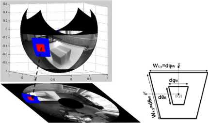
Fig. 6.Adapted block with fixed value dφ B =14°, dθ B =11° and adapted search window with fixed value dφ W =28°, dθ W =25° on the sphere and their projection on the image plane.
Where: N×N is the size of the image, I(x, y) represents the pixels of the reference image, Ï(x, y) is the predicted image obtained using the estimated vectors and the target image.
-
• The Structural Similarity (SSIM) measure is calculated on various windows of an image. The measure between two windows x and y of common size N×N is calculated as:
SSIM ( x , y ) =
(2^x^y + C)(2^ + C2)(мХ+My+ci )(^x+^У+C2)
(12)
V. Experiment Simulation And Result analysis
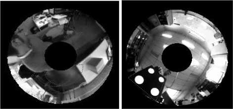
The sequences are obtained using a camera embedded on a mobile robot which is moving on a plan perpendicular to its optical axis. We consider that the camera is calibrated. In order to assess the proposed method, different types of motion are applied to the camera. The translation motion in axis-Y, rotation motion in axis-Z and the moving objects in the scene have been tested. We have chosen three types of sequences as follows: indoor sequence.1 (Fig. 7.a), with pure rotation of the camera, indoor sequence.2 (Fig. 7.b), with a fixed camera and moving objects in the scene and outdoor sequence.3 (Fig. 7.c), a camera placed on a moving car. The block sizes and search window used in the classical Block-Matching are ( B=15x15 and W=41x41 for sequence.1), ( B=13x13 and W=41x41 for sequence.2) and ( B=11x11 and W=41x41 for sequence.3). The two delimiter angles in our Adapted Block-Matching are ( dθ B =6°, dφ B =9 °, and dθ W =15°, dφ W =27° for sequence.1), ( dθ B =5°, dφ B =8°, and dθ W =15°, dφ W =27° for sequence.2) and ( dθ B =4°, dφ B =7 °, and dθ W =15°, dφ W =27° for sequence.3).
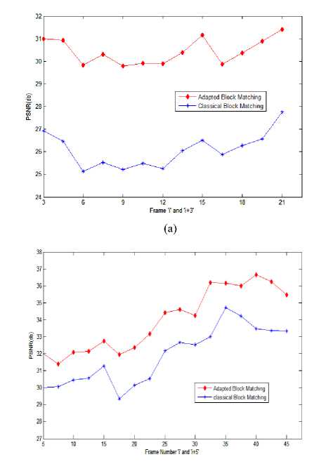
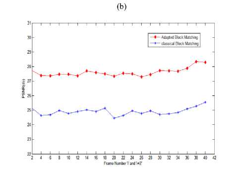
To evaluate the performance of our method on three sequences, we use the PSNR (11) and MSSIM (13). The PSNR in Fig. 8, MSSIM in Table1 and Error Image are computed from the predicted and the Reference images. The predicted image is estimated by using estimated motion for each pixel in the Reference image. The results of both indoor and outdoor sequences are illustrated respectively in Figures: Fig. 9, Fig. 10 and Fig. 11. In all these sequences, the motion estimated by our proposed method allows an estimation of accurate motion field in various scenes and different kinds of camera motions.
-
• The PSNR is expressed in the case of grayscale
images by:
(255)2
PSNR = 10log 0-
N - 1 N - 1
E E( i (i, j) -1 (i, j)]2
N x N
Where, μ x and μ y represent the mean of windows x, and y. σ x2 and σ y2 are the standard deviation; and C1 and C2 are included to avoid instability when μ x2 +μ y2 and σ x2 +σ y2 are very close to zero. The mean SSIM (MSSIM) is used to evaluate the overall quality:
M
MSSIM (X, Y) = — E SSIM (x, y) (13)
M i = 0
Where, X and Y are the reference and the predicted images. xi and yi are the intensity at the local window; and M is the number of local windows of the image [13].
(a) (b)
(c)
-
(a) Sequence.1: pure rotation camera (in Z-axis)
-
(b) Sequence.2: fixed camera and moving object
-
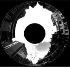
(c) Sequence.3: camera placed on a moving car (translation Y-axis)
Fig. 7. The Omnidirectional Sequences
(ii)
(c) (d)
(e) (f)
(c)
(g) (h)
-
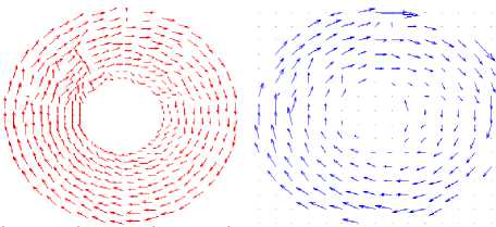
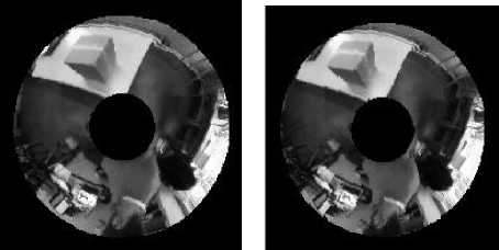
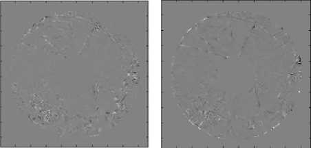
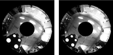
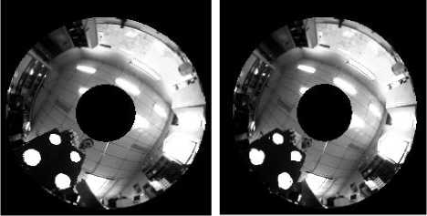
(a) Reference image (t) (b) Target image (t+3)
-
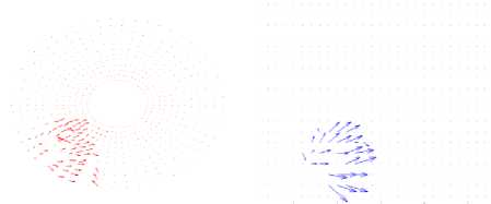
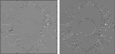
(c) Motion estimated (ABM) (d) Motion estimated (BM)
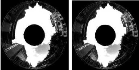
(e) Predicted image (ABM) (f) Predicted image (BM)
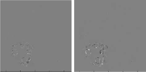
(g) Error image (ABM) (h) Error image (BM)
-
(a) Sequence.1 was used with a frame distance of3
-
(b) Sequence.2 was used with a frame distance of5
-
(c) Sequence.3 was used with a frame distance of2
Fig. 8.PSNR performances of Block Matching Algorithms
Fig. 9.Moving camera in pure rotation
(a) (b)
(a) (b)
(c) (d)
(e) (f)
(e) (f)
(g)
(h)
(g)
(h)
-
(a) Reference image (t) (b) Target image (t+5)
-
(c) Motion estimated (ABM) (d) Motion estimated (BM)
-
(e) Predicted image (ABM) (f) Predicted image (BM)
-
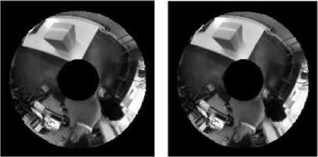
(a) Reference image (t) (b) Target image (t+2)
-
(c) Motion estimated (ABM) (d) Motion estimated (BM)
-
(e) Predicted image (ABM) (f) Predicted image (BM)
-
(g) Error image (ABM) (h) Error image (BM)
Table 1. Average of PSNR (db) and MSSIM of sequences used for verifying our motion model (ABM)
|
Sequences |
Mesures (Average) |
BM |
ABM |
|
Sequence.1 |
PSNR (db) |
26.28 |
31.90 |
|
MSSIM |
0.902 |
0.973 |
|
|
Sequence.2 |
PSNR (db) |
32.28 |
34.78 |
|
MSSIM |
0.979 |
0.990 |
|
|
Sequence.3 |
PSNR(db) |
25.94 |
28.12 |
|
MSSIM |
0.896 |
0.949 |
The mean PSNR and SSIM obtained from different sequences using the two implemented methods (BM) and (ABM) are indicated in Table 1. These results show that (BM) method is not appropriate in the case of omnidirectional images. The results obtained using our proposed method is superior to that obtained by classical methods. These results give the argument that methods dedicated to omnidirectional images are more robust and give more precise results. Finally, we can see that the measures are superior using approach with different camera motions. This means that the fixed support of neighborhood is not appropriate to omnidirectional images.
-
VI. Conclusion and future work
In this paper, we have proposed an adaptation of the Block Matching method in omnidirectional sequences using adapted blocks. The use of an adapted block instead of a rectangular block of fixed size improves the results of estimating motion in omnidirectional sequences. The experimental results have shown the effectiveness of blocks that are appropriate for motion estimation in omnidirectional images. Our Block-Matching method (ABM) allows interesting results in the different movements of the catadioptric camera contrary to the results obtained with the classical Block-Matching method proposed on the perspective images.
Indeed, in our various experiments, this method has enabled us to rebuild the various areas and contours in the predicted images and to reach PSNR and MSSIM of quality exceeding the results obtained with classical Block-Matching.
To make our Adapted Block Matching method more robust, it is desirable to integrate and to integrate other Block Matching research strategies [14] [2]. Nonetheless improvements can be introduced to increase the rate calculated and a good estimate of the movement for example by applying the method in a multi-resolution arrangement which consists in performing as many motion estimates as levels of decomposition [15].
References Motion Estimation for Omnidirectional Images using the Adapted Block-Matching
- A. Barjatya, “Block Matching Algorithms for Motion Estimation’’IEEE Trans on Digital Image Proc DIP 6620 Spring 2004 Final Project Paper.
- A. Nayak and B. Biswal “Evaluation and Comparison of Motion Estimation Algorithms for Video Compression” International. Journal. Image, Graphics and Signal processing, Vol.10, pp.9-18. 2013
- I. Tosic, I. Bogdanova, P. Frossard, and P. Vandergheynst. “Multiresolution motion estimation for omnidirectional images”. Proceedings of EUSIPCO 2005, antalya, September, 2005.
- I. Bogdanova, A. Bur, P. Farine, and H. Hügli. “Dynamic visual attention on the sphere”. Journal of Computer Vision and Image Understanding, Vol.114, pp.100–110, 2010.
- V. Thirumalai, I. Tosic, and P. Frossard. “Distributed coding of multiresolution omnidirectional images”. Image Processing, ICIP 2007, Vol.2, pp.II – 345 – II – 348, 2007.
- I. Tosic and P. Frossard. “Low bit rat compression of omnidirectional images”. Proceedings of PCS, pp.1–4, 2009.
- C. Demonceaux and P. Vasseur. “Markov random fields for catadioptric image processing”. Pattern Recognition, Vol.27 pp.1957–1967, 2006.
- A. Radgui, C. Demonceaux, E. Mouaddib, D. Aboutajdine and M. Rziza. “An adapted lucas-kanade’s method for optical flow estimation in catadioptric images”. Proceedings of the eighth workshop on Omnidirectional Vision and Camera Networks (OMNIVIS 08), 2008.
- Rameau. F., Sidibe. D., Demonceaux,. C. , Fofi, D. “Tracking Moving ObjectsWith a Catadioptric Sensor Using Particle Filter” Computer Vision Workshops (ICCV Workshops), IEEE International Conference. pp. 328 – 334, Barcelona 2011.
- C. Geyer and K. Daniilidis, “Paracatadioptric camera calibration,” IEEE Trans on Pattern Analysis and Machine Intelligence, vol. 24, ( 5), 2002.
- C. Geyer and K. Daniilidis, “Catadioptric projective geometry,” International Journal of Computer Vision, vol. 45, (3), pp. 223 – 243, December 2001.
- A. Radgui, C. Demonceaux, E. Mouaddib, M. Rziza, and D. Aboutajdine. “Optical flow estimation from multichannel spherical image decomposition”. Computer Vision and Image Understanding, Vol.115, pp.1263–1272, 2011.
- Z. Wang, A. C. Bovik, H. R. Sheikh and E. P. Simoncelli, "Image quality assessment: From error visibility to structural similarity," IEEE Trans on Image Processing, vol. 13, (4), pp. 600-612, avril 2004.
- S. Acharjee and S.S. Chaudhuri “Fuzzy Logic Based Three Step Search Algorithm for Motion Vector Estimation.” International Journal. Image, Graphics and Signal Processing, Vol. 2 pp.37-43, 2012.
- M. J. Kim, Y. G. Lee, and J. B. Ra, “A fast multi-resolution block matching algorithm for multiple-frame motion estimation”. IEICE Trans on Information and Systems, Vol. E88-D, (12), pp. 2819-2827, 2005.
