Multi-grid finite elements in calculations of multilayer oval cylindrical shells

Author: Pustovoi N.V., Grishanov A.N., Matveev A.D.
Journal: Сибирский аэрокосмический журнал @vestnik-sibsau
Section: Информатика, вычислительная техника и управление
Article in issue: 2 т.20, 2019.
Free access
The method of finite elements (FEM) is actively used in calculations of composite shell constructions (rotation shells, circle and oval cylindrical shells), which are widely used in space-rocket and aviation equipment. To calculate multi-layer oval cylindrical shells three-dimensional curvilinear Lagrange multi-grid finite elements (MGFE) are suggested. When building a k-grid finite element (FE), k nested grids are used. The fine grid is generated by the basic split of MGFE that takes into account its complex heterogeneous structure and shape. On k-1 large grids the move functions used for decreasing MGFE dimension are determined. The stress-strain state in MGFE is described by the elasticity theory three-dimensional task equations (without introduction of additional hypotheses) in local Cartesian coordinates systems. The procedure of building shell-type Lagrange MGFE with the use of Lagrange polynomials presented in curvilinear coordinate systems is demonstrated. With the size reduction of discrete models MGFE have constant thickness equal to the thickness of the shell. The Lagrange polynomials nodes coincide in thickness with the MGFE large grid nodes and are located on the shared borders of different module layers. The use of such MGFE generates approximate solutions sequences that uniformly and quickly converge to precise solutions. The main advantages of MGFE are as follows: they form discrete models with the dimension 102-106 times smaller than the basic models dimension and they generate small error solutions. Examples of calculations are given for four- and three-layer oval shells of various thickness and shape under both uniform and local loading with the use of 3-grid FE. Comparative analysis of the obtained solutions with the solutions built with the help of the software package ANSYS shows high efficiency of the suggested MGFE in calculations of multi-grid oval shells.
Программный комплекс ansys, elasticity, composite, oval cylindrical shell, multigrid finite elements, lagrange polynomials, conver- gence of the solution sequence, software package ansys
Short address: https://sciup.org/148321908
IDR: 148321908 | UDC: 539.3; | DOI: 10.31772/2587-6066-2019-20-2-174-182
Многосеточные конечные элементы в расчетах многослойных овальных цилиндрических оболочек
Метод конечных элементов (МКЭ) активно используется в расчетах композитных оболочечных конструкций (оболочки вращения, круговые и овальные цилиндрические оболочки), которые широко применяются в ракетно-космической и авиационной технике. Для расчета многослойных овальных цилиндрических оболочек предложены трехмерные криволинейные лагранжевые многосеточные конечные элементы (МнКЭ). При построении k-сеточного конечного элемента (КЭ) используется k вложенных сеток. Мелкая сетка порождена базовым разбиением МнКЭ, которое учитывает его сложную неоднородную структуру и форму. На k-1 крупных сетках определяются функции перемещений, применяемые для понижения размерности МнКЭ. Напряженно-деформированное состояние в МнКЭ описывается уравнениями трехмерной задачи теории упругости (без введения дополнительных гипотез) в локальных декартовых системах координат. Показана процедура построения лагранжевых МнКЭ оболочечного типа с применением полиномов Лагранжа, представленных в криволинейных системах координат. При измельчении дискретных моделей МнКЭ имеют постоянную толщину, равную толщине оболочки. Узлы полиномов Лагранжа по толщине совпадают с узлами крупных сеток МнКЭ и расположены на общих границах разномодульных слоев. Применение таких МнКЭ порождает последовательности приближенных решений, которые равномерно и быстро сходятся к точным. Основные достоинства МнКЭ состоят в том, что они образуют дискретные модели, размерность которых в 102-106 раз меньше размерности базовых моделей, и порождают решения с малой погрешностью. Представлены примеры расчетов четырех- и трехслойных овальных оболочек различной толщины и формы при равномерном и локальном нагружениях с применением 3-сеточных КЭ. Сравнительный анализ полученных решений с решениями построенных с помощью программного комплекса ANSYS показывает высокую эффективность предлагаемых МнКЭ в расчетах многослойных овальных оболочек.
Text of the scientific article Multi-grid finite elements in calculations of multilayer oval cylindrical shells
Introduction . When studying the stress-strain state (SSS) of elastic homogeneous and composite shells, various numerical methods are widely used [1–8]. Traditionally, in the theory of shells, displacements are decomposed into power series with respect to a coordinate normal to the middle surface. However, in this case, in the numerical study of the SSS of thick shells, it is necessary to take into account a large number of terms in the corresponding expansions [1; 2]. Effective numerical approaches to the study of elastic shells are mainly based on the finite element method (FEM) [3–5]. The construction of finite elements (FE) in curvilinear coordinates creates a number of difficulties [5], in particular, related to the fulfillment of conformance conditions, which is necessary for the monotonic convergence of the sequence of FEM solutions [6].
When calculating shells using the FEM, there are three main approaches: approximation of the shell by flat FE, using curvilinear two-dimensional FE and construction of three-dimensional FE. As shown by numerical experiments, in the latter case, the calculation of shells with inhomogeneous (micro-inhomogeneous) structure by FEM using the equations of three-dimensional elasticity theory without introducing additional simplifying hypotheses leads to systems of linear algebraic equations (SLAE) of high order (10 9 - 10 12 ). As a result, it becomes necessary to develop such FEM variants in which the corresponding SLAE has a small order and its solution provides an acceptable small error for displacements and stresses.
In [9; 10], the calculation of circular cylindrical shells with a fibrous structure using multi-grid finite elements (MGFE), in which displacements are approximated by Lagrangian polynomials of various orders, is proposed. When building a k -grid-based FE (k ≥ 2) k nested grids are used. The fine mesh is generated by the base partition of the MGFE, which consists of homogeneous single-grid FE (SGFE) of the 1st order and takes into account the non-uniform structure and shape of the MGFE. The remaining k - 1 large grids are used to reduce the dimension of the base partition, that is, the dimension of the MGFE. In [11], Lagrangian MGFEs are used to calculate multilayer circular cylindrical shells. The order of the Lagrange polynomials in the height of the MGFE was arbitrary and was not related to the number of layers.
In [12–14], the method of reference surfaces was proposed for calculating homogeneous and layered shells in the three-dimensional formulation. As unknowns, functions of displacements of these surfaces are chosen as functions of curvilinear coordinates. Displacements across the shell thickness are approximated using Lagrange polynomials of various orders, and displacements in the reference surfaces are given by functions that satisfy the boundary conditions. For displacements and deformations of reference surfaces, standard bilinear approximations and four-node curvilinear FEs are used [15], which distinguishes this approach from the analysis of the SSS of the shell using three-dimensional MGFE [10; 11].
In [16], it is noted that the use of non-circular cylindrical shells in aircraft industry allows to reduce the mass of the structure, effectively using the internal volume of pressurized cabins. The variability of the radius of curvature in the cross section of such shells in the general case creates certain difficulties in calculating the SSS using FEM. These difficulties are reduced if the noncircular cross section of the middle surface of the shell consists of several conjugate arcs of circles [16]. In this case, the three-dimensional Lagrangian MGFE developed in [10; 11] can be used to calculate multi-layer oval shells of different thickness, which greatly simplifies the application of FEM to analyze the SSS of oval shells.
The features of the MGFE in the calculation of oval shells are associated with the discretization rule, which is as follows. The proposed MGFEs with any partition have a constant thickness equal to the thickness of the oval shell. The nodes of the large MGFE mesh coincide with the nodes of Lagrange polynomials in the thickness of the shell and are located at the boundaries of the multi-modular layers. When refining discrete models, such MGFEs generate sequences of approximate solutions that converge uniformly and quickly to exact solutions.
The advantages of the proposed MGFEs are that they generate multigrid discrete models of oval cylindrical shells, which require 102 -106 times less computer memory than for the basic models. The calculations for multi-layer oval cylindrical shells of various thickness and shape show that the solutions obtained using the MGFE and using the ANSYS software package differ by a small value.
Multi-layer Lagrangian multi-grid finite elements. In [16], construction of the cross section of the middle surface of an oval shell with semi-axes a , b was shown (fig. 1). B – the point of conjugation of the arcs AB and BC with centers OR , Or and radii R , r . For given a , b the radii of circles R , r of the middle surfaces of circular cylindrical shells, fragments of which form an oval shell, are determined by the formulas i+k2 - V i+k2 „ i - k (^i+k2 - k)
r = a-----------, , R = a------------. ,
-
1 + k - V1 + k 2 1 + k - V1 + k 2
b n
k = tg a= — , y = — a . (1)
a 2
For the procedure of constructing a multi-grid discrete model for calculating a multilayer oval cylindrical shell we will consider the example of a 4-layer shell of constant thickness h , located in the Cartesian coordinate system 4
Oxyz , Oy - the axis of the shell. We have h = ^ h i , i = 1
h i – the thickness of the i -th layer of the shell, let h i = const, i = 1,...,4.
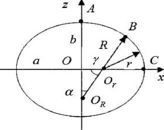
Fig. 1. Section of the shell middle surface
Рис. 1. Сечение срединной поверхности овальной оболочки
Without losing commonality of views, for simplicity, we assume that the geometric shape, physical characteristics, the discrete model, and the fixing of the oval shell are symmetrical with respect to the planes Oyz and Oxy . Therefore, we will consider a 1/4 part of the oval shell, that is, a cylindrical panel, which we denote by V 0 . The panel V0 consists of subregions (panels) V1 and V2 of circular cylindrical shells, respectively, with radii R and r (their middle surfaces, fig. 1). We believe that bonds between the components of the inhomogeneous structure of the shell are ideal. The procedure of constructing an MGFE for calculating a 4-layer panel V0 is considered on the example of a 4-layer three-grid FE (3GFE) Ve(,3p) (fig. 2), where the superscript in brackets corresponds to the number of nested grids that are used in the construction of 3GFE [10; 11].
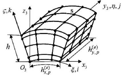
Fig. 2. Three-grid FE V e ( , 3 p ) for 4-layer oval shell
Рис. 2. Четырехслойный ТрКЭ V e ( , 3 p ) овальной оболочки
The circular cylindrical panel V p consists of 3GFE
-
V ,(3) , where e = 1,... N , N is the total number of 3GFE e , p p p
in the panel Vp, p = 1.2. Each 3GFE Ve^p consists of two-grid FE (2GFE) V2p, where m = 1,...,Mp , Mp is the total number of 2GFE. For simplicity, we assume that M = M7 = M . The area of 2GFE V,(2) of the panel V„ 12 m, p p consists of curvilinear homogeneous single-grid FE (SGFE) V^'p of the 1st order (p = 1.2), n = 1,..., Kp is the total number of SGFE. Fig. 3 shows the eight-node SGFE V(1) with characteristic dimensions
-
n , p
h ( n ) x h,nn ) x h ( n) , O . x . y . z , is a local Cartesian coordinate x , p y , p z , p 1 1 1 1
system. SGFEs V n ( , 1 p ) take into account the inhomogeneous structure and shape of 2GFE V m (2 , p ) . The stress state in SGFE V n ( , 1 p ) is described by the equations of the threedimensional problem of the theory of elasticity, which are represented in the local Cartesian coordinate system O 1 x 1 y 1 z 1, that is, a three-dimensional SSS is realized in SGFE.
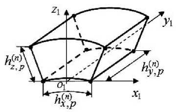
Fig. 3. Single-grid FE V n ( , 1 p )
Рис. 3. Односеточный КЭ V (1) n , p
The procedures of constructing SGFE and 2GFE for circular cylindrical panels are described in detail in [9]. For 3GFE Ve(,3p) , p = 1.2 we introduce three local coordinate systems: Cartesian O3x3y3z3, curvilinear O3ξηζ , and for nodes of a coarse 3GFE Ve(,3p) grid H3 – integer-valued ijk , where i, j= 1,..., 4 , k = 1,..., 5 , the nodes of the coarse grid H3 in fig. 2 are marked by dots, 80 nodes. The special feature of the 3GFE Ve(,3p) is that it has a constant thickness h equal to the thickness of the shell, that is, the thickness of the 3GFE V(3) does not e,p change when the partitioning of the discrete model is refined. Herewith, the nodes of the coarse grid H3 of 3GFE V(3) lie at the boundaries of the multi-modular e,p layers by thickness, fig. 2. The 3GFE Ve(,3p) with the characteristic dimensions hx(e,p)× hy(e,)p× h has the 3rd order in the coordinates x3 , y3 , and the 4th order in thickness h , that is, in the coordinate z3 (fig. 2). Note that when calculating the n -layer oval shell n -layer Lagrangian 3GFEs of the n -th order in thickness are used, the order of MGFE in the direction of each of the three coordinates is determined by the order of the corresponding Lagrange polynomial constructed on its coarse nodal grid.
3GFEs Ve(,13) , Ve(,32) , which differ from each other only in geometric dimensions and physical characteristics and correspond respectively to circular cylindrical panels V1 and V2 , are designed according to a single algorithm [10; 11], the brief essence of which is as follows. On the coarse grid H of the 3GFE V(3) , we determine the func-3 e,p tions of displacements u(3), v(3), w(3) , which are used to reduce the dimension of the 3GFE V(3) . The base func-e,p tion Nijk for a node S with integer coordinates i,j,k of a coarse grid H3 of the 3GFE Ve(,3p) (fig. 2) is represented as [10; 11]
N ijk ( α , η , ζ ) = L i ( α ) L j ( η ) L k ( ζ ), (2)
where α is the central angle corresponding to the arc hxe , p (fig. 2), i , j = 1,...,4, k = 1,...,5, Li ( α ), Lj ( η ), Lk ( ζ ) are Lagrange polynomials having the form
Li(α)=∏n1 α-αn , Lj(η)=∏n2 η-ηn , n=1,n≠i αi - αn n=1,n≠jηj -ηn n3
L k ( ζ ) = ∏ ζ ζ n . (3)
n = 1, n ≠ k ζ k - ζ n
Let the coarse grid node H 3 with coordinates i , j , k ( i , j = 1,..., 4 , k = 1,..., 5 ) correspond to an integer β , β= 1,...,80 . Using (2), (3), we will present functions of displacements u (3) , v (3) , w (3) in the form
80 8080
u(3)=∑Nβ(3)uβ(3), v(3)=∑Nβ(3)vβ(3), w(3)=∑Nβ(3)wβ(3),(4)
β=1 β=1
where u β (3) , v β (3) , w β (3) , N β (3) are displacements and shape functions of β -th node of the H 3 grid
The functional of the total potential energy П ( p 3) ( p = 1,2 ) for the 3GFE V e ( , 3 p ) is written as
M
-
(3) 1 (2) T (2) (2) (2) T (2)
-
p ∑ (( m , p ) m , p m , p ( m , p ) m , p ),
m = 1 2
p = 1,2, (5)
where K(2) is the stiffness matrix, P(2) , δ(2) are the m, p m, p m, p vectors of the nodal forces and displacements of the 2GFE Vm(2, p) corresponding to the coordinate system O3x3y3z3, T is the transposition.
Using (4), we express the vector of displacements δ(2) of 2GFE V(2) through the vector of nodal m, pm displacements δ(p3) of the coarse grid H3 of the 3GFE Ve(,3p) , thus obtaining the relation
-
(2) (3)(3)
δm,p = Am,pδp ,(6)
where A ( m 3 , ) p is a rectangular matrix,
-
(3) (3) (3)(3)
δ p = { u β , v β , w β }.
Substituting (6) into (5) and, following the principle of minimum total potential energy ∂ П ( p 3) ( δ ( p 3) ) / ∂ δ ( p 3) = 0, we obtain the relation K ( p 3) δ ( p 3) = P p (3) , where
M
K(3) = (A(3) )T K(2) A(3) , pm,pm,pm,p m=1
M
P p (3) = ∑ ( A ( m 3,) p ) T P m (2,) p , p = 1,2, (7)
m = 1
where K ( p 3) , P p (3) is the stiffness matrix and the vector of nodal forces of the 3GFE V (3) .
e , p
Remark. The dimension of the vector δ ( p 3) (i. e., the dimension of the 3GFE V e ( , 3 p ) ) does not depend on the total number M of 2GFE V (2) that make the 3GFE V (3) . m , p e , p
Consequently, the partitioning of the 3GFE Ve(,3p) into 2GFEs V(2) , and therefore also into SGFE V(1) , can be m, p n, p arbitrarily small, which makes it possible to take into ac- count the complex heterogeneous (micro-inhomogeneous) structure and shape of the circular cylindrical panels V1 and V2 .
Calculations show that the introduction of additional nodes of polynomials inside the layers allows reducing the error of the SSS values, but it increases the order of the SLAE and increases the estimated time of the problem.
The number of layers of 2GFE may be less than the number of layers of the shell. For example, when constructing a 4-layer 3GFE, one can use 2-layer 2GFE. This reduces the time costs in the calculation of the SSS with an insignificant change in the solution error.
In order to reduce the dimensionality of discrete models of shells, according to the procedure similar to the one discussed above, it is possible to construct 4-grid FE, and k -grid FE, k > 4 . The described method can be used to calculate multi-layer oval cylindrical shells with layers of both equal and different thickness.
Examples of the calculation of 4-layer oval shells of various thickness. Thick-walled shell. In the Cartesian coordinate system Oxyz we consider the solution of the FEM problem of deformation of a 4-layer oval cylindrical shell V 1 of constant thickness h = 12 cm with semiaxes а = 90 cm; b = 72 cm (fig. 1), Oy is an axial coordinate of the shell. The length of the shell is equal a 90
to 2 L = 1200 cm. We have: — = — = 7.5 < 10 , i. e. the h 1 12
shell V1 is thick-walled. The thicknesses of the homogeneous isotropic layers of the shell (starting from the inner layer) are equal: h1 = h 1/12 = 1 cm, h2 = h1 / 2 = 6 cm, h = h1 / 4 = 3 cm, h4 = h1 / 6 = 2 cm, which Young's moduli are equal: E1 = 10E kg/cm2, E2 = 3E kg/cm2, E3 = 5E kg/cm2, E4 = 20E kg/cm2, where E = 104, Poisson's ratio is equal v = 0.3 . For y = 0; 2L , we have u = v = w = 0 . Pressure q0 = 10 kg/cm2 is applied to the outer surface of the shell. In the calculations we use 1/8 of the oval shell, which we denote by V0 , of length L . A cylindrical panel V0 consists of two circular cylindrical panels V1 , V2 (conjugated along a common lateral bor- der) of length L with radii (their middle surfaces) R and r (fig. 1) defined by the formula (1).
For the panel V p we use 5 discrete models Ri „, ..., R s „, which consist of 3GFE V (31, p = 1.2. 1, p 5, p e , p
The base grid of the model R has the dimension n,p m П x mn x m3, where mП = 162 n +1, m2 = 649n +1, m3 = 24n +1, n = 1,...,5, (8)
where m 1 n is the dimension of the grid in the circumferential direction of the panel V p , mn 2 – in the axial direction, m 3 – in the radial direction. SGFE V (1) has dimensions n n , p
h(np x h(n)p x h(n), fig. 3, where h(n) = a„ r is the x,p y,p z,p x,pn,pn,pn, p radius of the lower surface of the SGFE, a„ = a „ / m1 , n, p p n corner angle a1 (a2 ) of the panel V1 (V2), according to (1) we have tga1 = — , a2 =П-a1, hynP = L/mn, h(n) = h1 / m3. The 3GFE VP3 with characteristic z, p n e, p dimensions 81 hXnp x 81 hynp x h1 consists of Lagrangian
2GFEs V (2) with characteristic dimensions m,p
9 h Xnp x 9 h ynp x h 1. In 2GFE and 3GFE, Lagrange polynomials of the form (3) have the third order in the circumferential and axial directions and the fourth order in the radial one. The nodes of the Lagrange polynomials (nodes of the coarse grids of 2GFE and 3GFE) lie on the common boundaries of the multi-modular layers by the shell thickness.
Tab. 1 shows the results of calculations of a cylindrical panel V 0 . Characteristic points A (in the plane Oyz ) and С (in the plane Oxy ) lie at the intersection of the extension of the semi-axes b and а with the outer surface of the shell in cross section y = L , in which we define displacements w n . Equivalent stresses g n (in the vicinity of points A , С ) are determined by the 4th theory of strength.
Table 1
The results of calculations of a thick oval shell ( а / h = 7.5 ; b / a = 0.8 )
|
n |
( w n ) A (mm) ( w n ) C |
5 w , n (%) A 5 w , n (%) C |
( n ) A (kg/cm2) ( g n ) C |
5a , n (%) A 3 a . n (%) C |
|
1 |
7.511 4.487 |
– |
371.43 144.21 |
– |
|
2 |
7.601 |
1.181 |
377.19 |
1.527 |
|
4.564 |
1.689 |
146.87 |
1.811 |
|
|
3 |
7.620 |
0.251 |
378.37 |
0.312 |
|
4.580 |
0.356 |
147.78 |
0.616 |
|
|
4 |
7.627 |
0.097 |
378.88 |
0.135 |
|
4.587 |
0.142 |
148.19 |
0.277 |
|
|
5 |
7.631 |
0.051 |
379.16 |
0.074 |
|
4.590 |
0.072 |
148.41 |
0.148 |
Table 2
The results of calculations of the oval shell for the model R 5 and the ANSYS software package ( b / a = 0.9 )
|
а / h |
w A (mm) w C |
0 w 0 A (mm) w С 0 |
5 w (%) A 5 w (%) С |
° A (kg/cm2) o C |
o 0 0 A (kg/cm2) o C |
5 o (%) A 5 o (%) С |
|
15 |
12.429 |
12.444 |
0.12 |
544.23 |
544.29 |
0.01 |
|
7.942 |
7.964 |
0.28 |
302.74 |
301.42 |
0.44 |
|
|
30 |
28.674 |
28.678 |
0.01 |
963.17 |
962.45 |
0.07 |
|
19.785 |
19.857 |
0.36 |
768.26 |
766.19 |
0.27 |
The relative errors at n = 2,...,5 are found by the formulas
5 O , n (%) = 100% x | o n -o n - 1 |/ o n ,
5 wn (%) = 100% x | w - w n _J/ w . (9)
The nature of the change 5 wn (%) , 5 o n (%) in values (tab. 1) shows the rapid convergence of stresses o n and displacements w n . Therefore, the values w 5 , o 5 at the points A and С can be taken as exact values with an error of less than 0.15 %. A comparison of the obtained results with the results of the task calculation in the ANSYS software package (SP) was conducted. Values of equivalent stresses and normal displacements, which are obtained using ANSYS SP, are equal to o A = 380.05 kg/cm2, o B = 149.52 kg/cm2 and w 0 = - 7.655 mm, w 0 = 4.609 mm.
A , B
The difference in results between the two variants of calculations is less than 0.5 % for displacements and less than 0.8 % for stresses.
The shell is of medium thickness and thin-walled shell. In the global Cartesian coordinate system Oxyz , we consider the solution by the FEM of the problem of deforming a 4-layer oval shell V 2 ( V 3 ) with semi-axes а = 90 cm; b = 81 cm, thickness h 2 = 6 cm ( h 3 = 3 cm) with the same ratios of the layer thicknesses as in the shell V 1 of p. 2.1, Oy is the axial coordinate of the shell V 2 ( V 3 ). The shell V 2 ( V 3 ) has a length of 2 L = 1200 cm, uniform loading q 0 = 10 kg/cm2 on the outer surface and is rigidly fixed on the ends. We have: -a- = — = 15 < 20 , i. e. V 2 is a shell of average h 2 6
thickness, a- = — = 30 > 20 , which means V 3 is a thin- h 3 3
walled shell. In the calculations we consider 1/8 of the oval shell V 2 ( V 3 ). When constructing solutions using the FEM, we use the previously considered 3GFE (fig. 2) and the grinding law (8). The calculation results are given in tab. 2, where designations are introduced: w A , w C , o A , o C are the displacements and equivalent stresses found at the points A , С (see p. 2.1); w A , w C , o A , o C are displacements and equivalent stresses calculated in points A , С using SP ANSYS.
Relative errors are determined by the formulas
( 5 w (%)) A = 100% x | w A - wa |/ w A , ( 5 o (%)) A = 100% x | o 0 A -o A |/ o 0 A , ( 5 w (%)) C = 100% x | w C - w C |/ w C , ( 5 o (%)) C = 100% x | o C -o C |/ o C . (10)
The performed calculations show a small error (less than 1%) in the spread of the results obtained using the 3GFE and ANSYS software package for thin, medium and thick 4-layer oval shells.
The dimension of the base model, which is represented by SGFE, is approximately 1.9 x 10 9 node unknowns, the width of the SLAE tape is 588550. The corresponding three-grid model has 108295 node unknowns, the width of the SLAE tape is 2775. Realizing the FEM reduces the order of SLAE by a factor of 1.76 x 10 4 and requires 3.73 x 10 6 times less computer memory capacity than for the base model. The number of 3GFE (160 FE) used for the calculation is approximately 80 times less (depending on the value a / h ) than the total amount of FEs (1.2 x 10 4 - 1.4 x 10 4 ) used in ANSYS.
An example of the calculation of a 3-layer oval shell of complex shape with local loading. In the Cartesian coordinate system Oxyz we consider the problem of deforming a 3-layer oval cylindrical shell with semi-axes а = 90 cm, b = 63 cm, thickness h = 3 cm, Oy is the axial coordinate of the shell. The length of the shell is 2L = 400 cm. At y = 0; 2L the ends of the shell are clamped. All isotropic homogeneous layers of the shell have thickness of h /3. The Young's moduli of the layers (starting from the inner) are: E1 = 6E kg/cm2, E2 = 2E kg/cm2, E3 = 10E kg/cm2, where E = 104, the Poisson's ratio for all layers is v = 0.3 . The form, loading and fixing of the shell are symmetrical with respect to the Oyz and y = L planes, therefore in calculations we use 1/4 of the shell, which we denote: panel V 4 , fig. 4 shows its median surface. A panel area V4 of length L consists of two circular cylindrical panels V3 and V 4 (of length L ), respectively, with corner angles a = 350 ; Y = 550 . The panel V4 has two holes (rectangular in plan) with dimensions l = L/6, S1 = rу/2 (fig. 4). On the outer surface of the panel V3 in the local area of dimensions L / 3 < y < 2L / 3, S2 = Ra , pressure q0 = -1 kg/cm2 is applied, as shown in fig. 4. When calculating a cylindrical panel V4 , we use a three-layer 3GFE with parameters, which were introduced earlier, and discrete models Rn (n = 1,...,5), for which the grids of basic partitions Rn0 have the dimension mn = 324n +1, m2 = 486n +1, тП = 6n +1, n = 1,...,5. (11)
Tab. 3 shows the calculation results for the models Rn , n = 1,...,5 . Values w5, a5 for the model R5, defined in points A, С (fig. 4, 5), can be taken as accurate values with an error of less than 0.2% for displacements and less than 0.1% for stresses. The values of equivalent stresses a0 and normal displacements w0 obtained in ANSYS are aA = 75.16 kg/cm2, aC = 43.52 kg/cm2 and wA = -6.210 mm, wC = 2.534 mm. The difference in the results of the two calculations is less than 0.3% for displacements and less than 0.6 % for stresses.
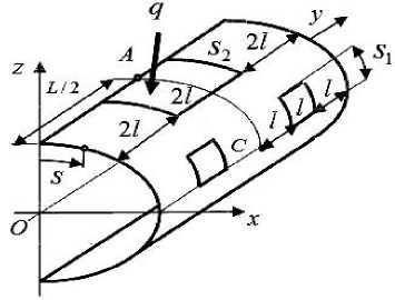
Fig. 4. Design scheme for 1/4 of the shell, panel V 4
Рис. 4. Расчетная схема 1/4 части оболочки, панель V 4
Table 3
The results of calculations of a thin oval shell with holes ( a / h = 30 ; b / a = 0.9 )
|
R n |
( w n ) A (mm) |
5 w , n (%) A |
. n A (kg/cm2) |
5a , n (%) A |
|
( w n ) C |
5 w , n (%) C |
( a n ) C |
5 a , n (%) C |
|
|
R 1 |
–6.041 |
– |
78.21 |
– |
|
2.390 |
39.92 |
|||
|
R 2 |
–6.155 2.491 |
1.852 4.055 |
74.57 42.88 |
4.881 6.903 |
|
R 3 |
–6.182 |
0.437 |
74,91 |
0.454 |
|
2.513 |
0.875 |
43.13 |
0.580 |
|
|
–6.193 |
0.178 |
75.05 |
0.187 |
|
|
R 4 |
2.522 |
0.357 |
43.23 |
0.231 |
|
–6.198 |
0.081 |
75.12 |
0.093 |
|
|
R 5 |
2.527 |
0.198 |
43.26 |
0.069 |
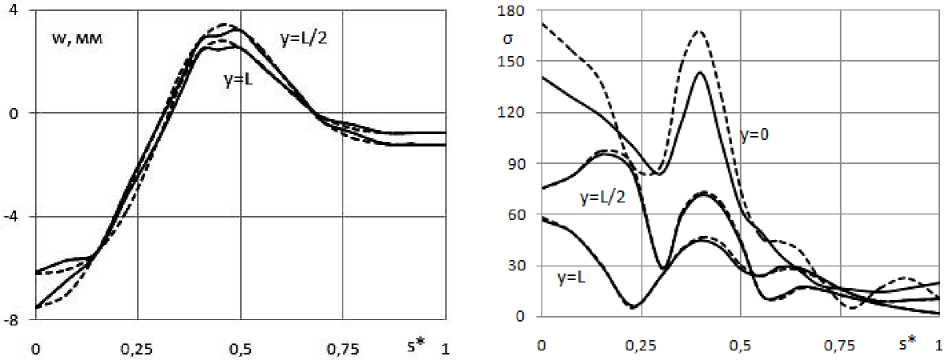
Fig. 5. Distribution of deflections w ( а ) and of stress a ( b ) over the upper shell surface in cross-sections: у = 0; L /2; L . Three-grid FE - solid line; SP ANSYS - dashed line
Рис. 5. Распределение прогибов w ( а ) и напряжений a ( b ) по верхней поверхности оболочки в поперечных сечениях: у = 0; L /2; L . ТрКЭ - сплошная линия; ПК ANSYS - штриховая линия
Fig. 5 shows the distribution of displacements ( w = w 5 ) in sections y = L /2; L and stresses ( g = g 5 ) in sections y = 0; L /2; L on the outer surface of the shell, depending on the parameter л * = л / P ; л , P is the distance from the axis Oz to the point on the outer surface of the shell and to the point С (fig. 4). The SSS calculation was fulfilled using the 3GFE (full line) and using ANSYS (dashed line).
A noticeable discrepancy in the stress distribution is observed only in the clamping area. In the rest of the complex shell structure, one can observe an acceptable in engineering calculations coincidence of the SSS, obtained by means of 3GFE and ANSYS SP.
The FEM implementation for the multigrid model R 5 reduces the order of the SLAE solved by 5625 times and requires 3.88 x 10 5 times less computer memory than for the basic model R 5 0 , which uses only SGFE. The number of 3GFE used for calculation in a discrete model R 5 (240 FE) is approximately 300 times less than the number of FE used for calculation in ANSYS (73892 FE).
Thus, the use of 3GFE in the analysis of SSS allows saving computer resources significantly, which greatly expands the possibilities of FEM in a variant of multigrid modeling.
Conclusion. The high efficiency of using curvilinear Lagrangian MGFE in the analysis of three-dimensional SSS of multilayer oval cylindrical shells is shown. The implementation of the FEM using MGFE requires 10 2 - 10 6 times less computer memory than with the use of SGFE or ANSYS SP, and allows analysis of the SSS of shells with a small error of results.
References Multi-grid finite elements in calculations of multilayer oval cylindrical shells
- Noor A. K., Burton W. S. Assessment of computational models for multilayered composite shells // Applied Mechanics Reviews. 1990. Vol. 43. P. 67-97.
- Reddy J. N. Mechanics of laminated composite plates and shells: theory and analysis. CRC Press, 2004. 858 p.
- Zienkiewicz O. C., Taylor R. L., Zhu J. Z. The finite element method: its basis and fundamentals. Oxford: Elsevier Butterworth-Heinemann, 2013. 715 p.
- Норри Д., де Фриз Ж. Введение в метод конечных элементов. М.: Мир, 1981. 304 с.
- Голованов А. И., Тюленева О. И., Шигабутдинов А. Ф. Метод конечных элементов в статике и динамике тонкостенных конструкций. М.: Физмат. лит, 2006. 392 с.
