Multi quadrant operation of brushless direct current motor drive with pi and fuzzy logic controllers

Author: B.V. Arun Kumar, G. V. Marutheswar
Journal: International Journal of Information Engineering and Electronic Business @ijieeb
Article in issue: 3 vol.11, 2019.
Free access
This paper presents that the simulation of control of three phase Brushless Direct Current (BLDC) motor in all four quadrants with PI and Fuzzy Logic controllers (FLC). Traditionally the speed control of motors is carried out by conventional motors with using P, PI, PID and some other control techniques [5]. But it provides a chance to occurrence of nonlinearity & uncertainties that causes some internal and external parameter errors. The efficient speed control in four quadrant operation can be achieved by using a fuzzy logic controller. The improvisation of Brushless Direct current motor drive through fuzzy logic controller in all four quadrants is done using simulink/MATLAB [7].
BLDC motor, Fuzzy Logic controller (FLC), Multi quadrant operation, FPGA
Short address: https://sciup.org/15016175
IDR: 15016175 | DOI: 10.5815/ijieeb.2019.03.04
Text of the scientific article Multi quadrant operation of brushless direct current motor drive with pi and fuzzy logic controllers
Published Online May 2019 in MECS
In various industrial and home applications Brushless Direct Current motors are used in extent manner. Due to advantages of Brushless DC motors there is improved control schemes to predict the presentation of the motor. In a conventional brushed Direct Current motor, the brushes are accountable for making the mechanical contact with a set of electrical contacts on the rotor referred to as the commutator. This forms an electric circuit connecting the DC electrical source and the armature coil windings. While the armature rotates, the motionless brushes come in contact with dissimilar sections of the commutator. The rotating commutator and the brush system shape a set of electrical switches which operate in a series to allow electric current to flow through the armature coils nearby to the field which may be an electromagnet or a permanent magnet. In a Brushless Direct Current motor, armature coils do not move, and in its place the permanent magnets rotate. Therefore the armature remains stationary which avoids the difficulty of how to move current to a moving armature. In a Brushless Direct Current motor, the commutator assembly is replaced by an electronic controller which is programmed to perform the coil switching [1]. The major advantages of Brushless DC motor such as elevated efficiency, extended operating life, low down noise, and variable high speed ranges.
Brushless Direct Current motors come across applications in each section of the market such as appliances, industrial control, automation, aviation, etc. Brushless Direct Current motor operation control can be divided into three most important types such as constant load, varying loads and positioning applications. The BLDC motor consruction is shown below in Fig.1
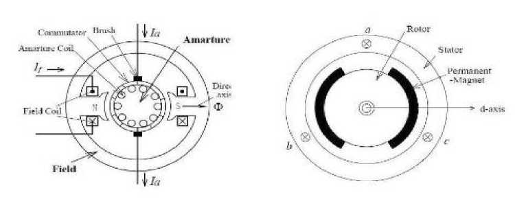
Fig.1 BLDC Motor constructions
II. Modeling Of The Brushless Direct Current (BLDC) Motor Drive System:
A. Modeling of BLDC Motor
abc phase changeable and d-q axis models are used mathematically in BLDC motor. In a BLDC motor the back emf is trapezoidal in nature implies that non sinusoidal mutual inductance among stator and rotor windings, and then renewed in to d-q axis representation. This method is not having a exacting advantage, so we go for adc phase variable technique. Here we assumed that BLDC motor is star linked through isolated neutral[2]. In BLDC motor modeling the subsequent assumptions are not drenched [4].
-
i. Self and Mutual inductances made i.e.
-
ii BLDC Motor is are invariable and stator resistance of all windings is like.
-
iii. Semiconductor devices are ideal in nature.
The balanced circuit of the BLDC servomotor drive scheme is shown. The line to line voltage equations in matrix equation (1) is given as
"Vab
R -R
V bc = 0 R
• VJ L-R 0
0Uia
-R ib +0
-R ic
M-L L-M 0
fl+IB
M - L
L-M
+
Mutual inductance (M) is neglected as compared to the self-inductance (L); as a result matrix equation(2) can be rewritten as
Ell
R 0 -R
-R R 0
-R
-R
l №
L 0 -L
-L
ea - eb I eb - ec | ec - 6 a
L
-L L
l *0
+
Where
L=Self-inductance.
M= per phase Mutual inductance;
R=per phase stator winding Resistance;
ea, eband ec= phases a, b, and c Back EMFs;
ia, В , ic = phase streams of phases a, b, and c, individually.
In BLDC motor, torque generated by means of the BLDC motor can be expressed equation (3) as shown below
T e =(6 a l a + 6 b l b +6 c l c ) / to=KJ (3)
Where ia = iй = ic= I, ю is the speed in r/s, and K£is the torque invariable. Since this torque generated by means of the BLDC motor is used to conquer the differing torques of inertia and load, it can also be written equation (4) as
ТеВ+ KA, dt+В м М (4)
Where T L = load torque
JM = inertia, and BM = friction invariable of the BLDC servomotor .The load torque can be articulated in requisites of load inertia J L and friction B L mechanism in equation (5) as
T^^(5)
The power output developed by BLDC motor is shown below equation (6) and (7) as
P = T^
E = 6a= 6b = 6c Khm
Where K b is back Electro Motive Force constant, E is back Electro Motive Force per phase and ω is the speed in r/s. It possibly will be observed that, the function shown in table I are 120 degree phase shifted.
B. Modeling of Back Electro Motive Force (EMF) using Rotor Position
^ а еь . ^с.
ojmAm
f as( 9 r ) f bs (9 r ) . f cs (9 r )
If ib < (ib + hb) S 3 OFF and S 6 ON 5S =0
If ic < (iC - hb) S 5 ON and S 2 OFF Sc =1
If ic < (iC - hb) S 5 OFF and S 2 ON 5C =0
Where fas(9r) , fbs(9r) , fcs(9r) are unit function producer to analogous to the trapezoidal induced emfs of the BLDCM as a function of 9r . The fbs(9r),fcs(9r) are similar to fas(9r) but phase displacement of 120 degrees.
( 9r 6
n
,
0 < 9r < n
f as (9 r ) = 4
(n-9 r )6 П
-1
• 6 <
• T<
■ T<
9r< -r 6
9 r
9 r
<
<
7П (9)
6 11П
Where, hb is the hysteresis band approximately the three phase’s position currents, according to above switching state of the inverter output voltage equations (10),(11),(12) are given below
Па = |[ 25Л-5Я-5С]
пь=|[ -5Л + 25Я-5С]
Пс = |[ -5л-55 + 25с](12)
<(9 r
—
2n)6 , — < 9r< 2n
J n 6 r
Accordingly f bs (9r) and fcs(9r) can be designed.
The modeling of the brushless direct current motor includes the reliasation as a function of rotor electrical angle with hall sensors which can be scheduled in below table I.
Table 1. Hall sensors modeled as a function of rotor angle
|
Theta_elec |
h a hb hc |
|
00 - 600 |
1 0 1 |
|
60o - 120o |
0 0 1 |
|
120o - 180o |
0 1 1 |
|
1800-2400 |
0 1 0 |
|
240o - 300o |
1 1 0 |
|
300o - 360o |
1 0 0 |
-
III. Hysteresis Current Controller (Hcc)
The Hysteresis current controller serves to the production of the switching signals for the inverter. hysteresis-band Pulse Width Modulation is on the whole an immediate feedback control of current in Pulse Width Modulation(PWM) where the actual current repeatedly tracks the domination current within hyssteresis-band.Fig.3.2 explains the operation principle of hysteresis-band Pulse Width Modulation(PWM) for half controlled bridge inverter. The control circuit produces the sine position current and it’s compared with real phase current wave. The current go beyond upper band limit the upper switch is off and lower switch is on. As the current go beyond lower band boundary upper switch is on and lower switch is off like this control of the other phase going on.
The switching logic is formulated as given below.
If i a < (i a - h b ) If i a < (i a + h b ) If i b < (i b - h b )
S1 ON and S4 OFF 5Л = 1
S 1 OFF and S 4 ON 5Л = 0
S 3 ON and S 6 OFF SB = 1
-
IV. Inverter Control
Fig.2 shows a basic block diagram of Brushless Direct Current Motor (BLDCM) control performance for a three phase motor. The circuit uses six power transistors, Metal Oxide Field Effect Transistors or IGBTs. The switches are controlled consequently to provide suitable commutation to the windings in synchronism by means of rotor dislocation, given that the function of the commutator.
In Brushless Direct Current Motor, two phases conduct at a time and the third one drifts and each phase conducts for 1200 electrical degrees. The commutation moment occurs when the rotor near by a position reflecting 300 electrical. From that position, one conducting phase is chopped out and the floating phase starts conducting current and so on at an additional position of the rotor subsequent to 1200 electrical to maximize torque, progress the efficiency and lower the torque ripple
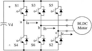
Fig.2. VSI fed BLDC Motor Drive
-
V. Pi Controller
The PMBLDCM drive having a speed controller, position current generator, Pulse Width Modulation current controller, position sensor, the motor and IGBT based voltage source inverter with current controlled condition. The motor speed is matched with its position value and the speed error is processed with PI speed controller.
e(t)= w ref -w m (t)
Where w m (t) is matched with the reference speed toTe ^ and the output error is estimated at the nth sampling instant is shown in equation (14) as.
T ref =T ref (t-1)+K p [e(t)-e(t-1)]+K i e(t) (14)
Where K p and Ki are the gains of PI speed controller[8].
The output of the controller is considered as the reference torque. A boundary is put on the speed controller output depending on the allowable highest winding currents. The position current producer block produces the three phase position currents ia, ib, ic using the some degree of peak currents magnitude decided by the controller and the position sensor. The simulink block diagram representation of Brushless Direct Current Motor with PI Controller Shows in below Fig.3
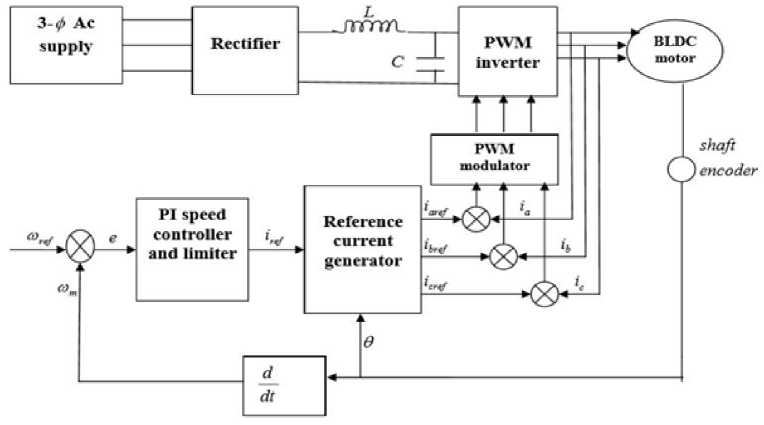
Fig.3. simulink block diagram representation of Brushless Direct Current Motor with PI Controller
-
VI. Fuzzy Logic Controller (Flc)
The controller with fuzzy logic was applied to the speed controller by replacing the PI controller. The fuzzy logic controlled Brushless Direct Current Motor drive system block diagram is shown in Fig.4
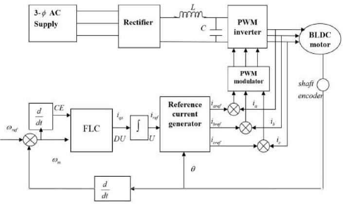
Fig.4. simulink block diagram representation of Brushless Direct Current Motor with FLC
The controller is calculated the input variable such as speed error(E) and change in error in speed(CE).The output variable is known as position or reference current Iref which is a component of torque and is obtained by using the change in position current at output of controller. The pattern of error signal is observed by controller and corresponding otput DU so that the real speed compared with the reference speed Wref.the FLC is havinf the two input signals,first one is the error E = mref — rnm and second one is the change in error CE, which is connected to the derivative — = CC = CE, dt At Ts where ДЕ in the sampling time Es ,CE is preportional to ^|. The output of the controller DE in brushles direct current motor drive is A iqs current .The signal is incorporated to generate the real control signal U or current iqs . We can write those equations (15),(16) as jDU = /K1Edt+ JK2 CE dt (15)
U = K 1 jEdt + K 2 E (16)
where K 1 and K 2 are gain factors together with the summation process.
The adaptive gains with non linear charecteristics in extending the same principle we can write a FLC algorithm for P and P-I-D. The fuzzy membership functions for the input variable and output variable are selected as follows:
Positive Large: PL Negative Large: NLPositive Medium: PM Negative Medium: NM Positive Small: PS Negative Small: NS And zero: ZO
The speed error (E) and change in error (CE) is distinct in the ranges are shown equqtion (17) and (18) below
-1 < tie < +1 (17)
and
-1< M ee < +1 (18)
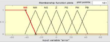
Fig.5. The speed error(E) Fuzzy membership function
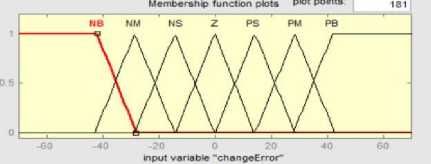
Fig.6. The change in error(CE) Fuzzy membershipfunction
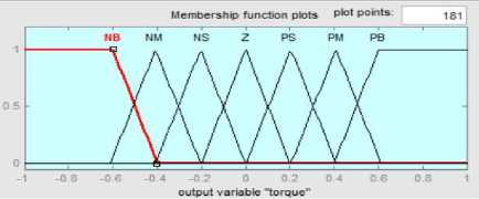
and the output variable reference current change ∆i qs is define in the range equation (19) is shown below
-1 < Дiqs < +1 (19)
The member ship functios are taken as traingular shpae due that resulting most excellent control performance and effortlessness. The membership function for the error and the change in error and the change in torque reference current are shown in Fig.5, Fig.6, and Fig.7 respectively. For all variables seven levels of fuzzy membership function are used Table .II show the rule base table that was used in the system.
-
A. Rule base Table :
The following Table 2 represents the Rules for fuzzy lolgic control
Table 2. Rule base table
|
e/ce |
NL |
NM |
NS |
ZO |
PS |
PS |
PL |
|
NL |
NL |
NL |
NL |
NL |
NM |
NS |
ZO |
|
NM |
NL |
NL |
NL |
NM |
NS |
ZO |
PS |
|
NS |
NL |
NL |
NM |
NS |
ZO |
PS |
PM |
|
ZO |
NL |
NM |
NS |
ZO |
PS |
PM |
PL |
|
PS |
NM |
NS |
ZO |
PS |
PM |
PL |
PL |
|
PM |
NS |
ZO |
PS |
PM |
PL |
PL |
PL |
|
PL |
ZO |
PS |
PM |
PL |
PL |
PL |
PL |
-
VII. Results And Discussion
-
A. PI Controller
Here we obtain the simulation results of Brushless direct current motor drive with PI controller. Fig.8represents speed variation four qudrant operation with small over shoot[8].
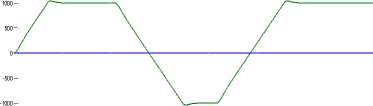
-1500
Time(sec)
Fig.8. speed vs. time
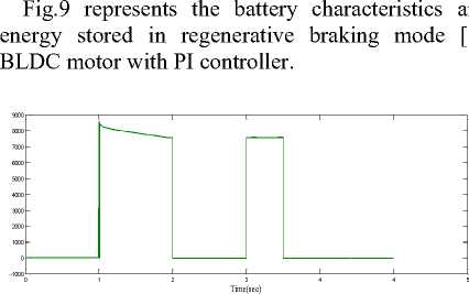
the of
Time(sec)
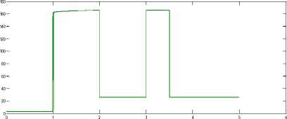
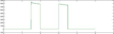
Fig.9. Battery charecteristics
The stator current ia is having more magnitude in motoring mode and reduced to low value in braking mode. Fig.10 represents the stator current in four quadrant mode
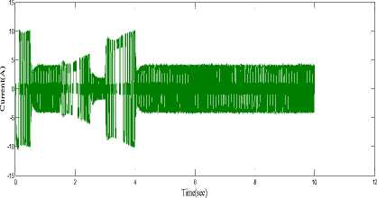
Fig.10. Stator current i a
The variation in the amplitude of the stator back EMFs in one of all the three phases are clearly visible in the scope results shown in Fig.11 The trapezoidal shape is also seen.
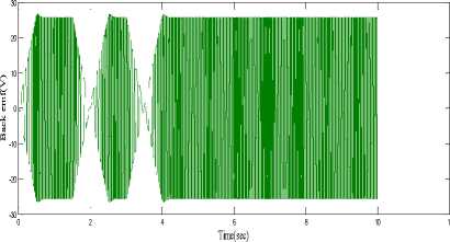
Fig.11. Back emf wave form e a
-
B. Quadrant determination
Table 3. Quadrant determination
|
Time |
0 |
0.8 |
1.0 |
1.5 |
2. 0 |
2.6 5 |
2.7 5 |
3. 0 |
|
Refere nce speed |
0 |
100 0 |
100 0 |
100 0 |
0 |
100 0 |
100 0 |
0 |
|
Applie d torque |
0 |
0 |
+1 |
-1 |
-1 |
-1 |
+1 |
0 |
|
Quadr ant |
Initia l |
I |
I |
II |
II |
III |
IV |
- |
The following table (III) represents that quadrant determination for given applied torque and speed
-
1. From start up to 0.8s, the torque applied is positive. That is, the motor is operation in the first quadrant, forward motoring.
-
2. At time 1.5s negative torques is applied. This implies that a sudden brake is applied. The rotor speed is drastically brought to zero at 2.0 s; this is the second quadrant of operation, forward braking.
-
3. At 2.65 s the motor is forced to rotate in the reverse direction, the applied torque remains negative. Since torque and speed are negative, the motor is in commission in the third quadrant, reverse motoring.
-
4. While at 2.75 s the load torque applied is positive, this is reverse motoring and sudden brake is applied which drops [9] down the rotor speed to zero rpm, indicating that the motor is in the fourth quadrant, reverse braking, of speed torque characteristics.
Here the below table IV represents that peak time, rise time, settling time and over shoot in case of forward and reverse motoring modes.
Table 4. Time calculation in forward motoring and reverse motoring modes respectively.
|
Quadrant |
Peak time |
Rise time (tr) |
Settling time (ts) |
Over shoot |
|
Forward motoring(I) |
0.55 |
0.45 |
0.65 |
0.04 |
|
Reverse motoring(III) |
2.55 |
0.45 |
2.65 |
0.04 |
-
C. Fuzzy Logic Controller
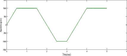
Fig.12. speed vs. time
The variation in the amplitude of the stator back EMFs in one of all the three phases with Fuzzy Logic controller are clearly visible in the scope results shown in Fig.13. The trapezoidal shape is also seen. The trapezoidal what we obtain will be more efficient than compared with PI controller.
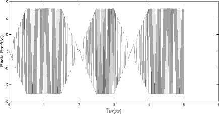
Fig.13. Back emf waveform e a .
Fig.15 represents the battery characteristics [10, 11] of Brushless direct current motor motor with FLC
The stator current i a is having more magnitude in motoring mode and reduced to low value in braking mode. Fig.14represents the stator current in four quadrant mode
Time(sec)
Fig.15. Battery Charecteristics
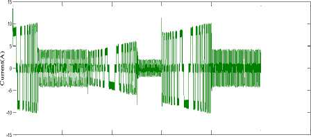
Fig.14. The stator currents of the three phases
Time (sec)
-
D. Quadrant determination
The following table (III) represents that quadrant determination for given applied torque and speed.
-
1. From start up to 1.0 s, the torque applied is positive. That is, the machine is operation in the first quadrant, forward motoring.
-
2. At time 1.75 s negative torques is applied. This implies that a sudden brake is applied. The rotor speed is drastically brought to zero at 2.0 s; this is the second quadrant of operation, forward braking.
-
3. At 2.5 s the motor is forced to rotate in the reverse direction, the applied torque remains negative. Since torque and speed are negative, the motor is operating in the III quadrant, reverse motoring.
-
4. While at 2.75 s the load torque applied is positive, this is reverse motoring and sudden brake is applied which drops down the rotor speed to zero rpm, indicating that the motor is in the fourth quadrant, reverse braking, of speed torque characteristics.
Table 5. Quadrant determination
|
Time |
0 |
0.5 |
1.0 |
1.5 |
2.0 |
2.50 |
2.75 |
3.0 |
|
Reference speed |
0 |
1000 |
1000 |
1000 |
0 |
-1000 |
-1000 |
0 |
|
Applied torque |
0 |
0 |
+1 |
-1 |
-1 |
-1 |
+1 |
0 |
|
Quadrant |
Initial |
I |
I |
II |
II |
III |
IV |
- |
Here the below table VI represents that peak time, rise time, settling time and over shoot in case of forward and reverse motoring modes.
Table 6. Time calculation in forward motoring and reverse motoring modes respectively
|
Quadrant |
Peak time |
Rise time (tr) |
Settling time (ts) |
Over shoot (%) |
|
Forward motoring(I) |
0.5 |
0.40 |
0.50 |
0.0 |
|
Reverse motoring(III) |
2.5 |
0.40 |
2.50 |
0.0 |
From above discussion we can say that the BLDC motor drive using fuzzy logic controller give zero percent of overshoot compare to conventional or PI controller both in forward and reverse motoring modes respectively.
-
VIII. Conclusion
Refernces
-
[1] R.Krishnan and A. J. Beutler, “Performance and design of an axial field permanent magnet synchronous motor servo drive,” in Proc. IAS Annu. Meeting , pp. 634-640, 1985.
-
[2] Sim power Systems for use with Simulink, user‟s guide, Math Works Inc., Natick, MA, 2002. Math Works, 2001, Introduction to MATLAB, the Math Works, Inc. 6. T.J.E. Miller, “Brushless Permanent Magnet & Reluctance Motor Drives” Clarendon Press, Oxford , Vol.2, pp: 192199, 1989
-
[3] Zhen-Yu Zhao. 1993. Masayoshi Tomizuka and Satoru Isaka Fuzzy Gain Scheduling of PID controllers. IEEE transactions on systems, man and cybernetics. 23(5).
-
[4] P. Pillay and R. krishnan. 2002. Modelling simulation and analysis of a Permanent magnet brushless Dc motor drive. IEEE trans. Ind Applicant. 26: 124-129.
-
[5] Chung-Wen Hung, Jen-Ta Su, Chih-Wen Liu, ChengTsung Lin and Jhih-Han Chen. 2010. Fuzzy Gain Scheduling PI controller for Sensorless four switches three phase BLDC motor. IEEE 978-1-4244-47831/10.
-
[6] Ji Hun, Li Zhiyong. 2008. Simulation of Sensorless Permanent magnetic brushless DC motor control System. Proceedings of the IEEE International conference on automation and logistics. September, Quigdao, China.
-
[7] N. J. Patil, R. H. Chile and L. M. Waghmare. 2010. Fuzzy Adaptive Controllers for Speed Control of PMSM Drive. International Journal of Computer Applications (0975 -8887). 1(11).
-
[8] George K. I. Mann, Bao-Gang Hu and Raymond G. Gosine. 1999. Analysis of Direct Action Fuzzy PID Controller Structures. IEEE transactions on systems, man, and cybernetics-part b: cybernetics. 29(3).
-
[9] C.Hua and S.J.Kao,“Design and implementation ofregenerativebrakingsystemforelectricbicyclesbasedonD SP,”in Proc.6thIEEEConf.IndustrialElectron.pplications,B eijing ,2011,pp.703–707.
-
[10] W. Cui, H. Zhang, Y.-L. Ma, and Y.-J. Zhang,
“Regenerative braking control method and optimal scheme for electric motorcycle,” in Proc. Int. Conf. Power Engineering, Energy and Electrical Drives, Spain , 2011, pp. 1–6.
References Multi quadrant operation of brushless direct current motor drive with pi and fuzzy logic controllers
- R.Krishnan and A. J. Beutler, “Performance and design of an axial field permanent magnet synchronous motor servo drive,” in Proc. IAS Annu. Meeting, pp. 634-640, 1985.
- Sim power Systems for use with Simulink, user‟s guide, Math Works Inc., Natick, MA, 2002. Math Works, 2001, Introduction to MATLAB, the Math Works, Inc. 6. T.J.E. Miller, “Brushless Permanent Magnet & Reluctance Motor Drives” Clarendon Press, Oxford, Vol.2, pp: 192- 199, 1989
- Zhen-Yu Zhao. 1993. Masayoshi Tomizuka and Satoru Isaka Fuzzy Gain Scheduling of PID controllers. IEEE transactions on systems, man and cybernetics. 23(5).
- P. Pillay and R. krishnan. 2002. Modelling simulation and analysis of a Permanent magnet brushless Dc motor drive. IEEE trans. Ind Applicant. 26: 124-129.
- Chung-Wen Hung, Jen-Ta Su, Chih-Wen Liu, ChengTsung Lin and Jhih-Han Chen. 2010. Fuzzy Gain Scheduling PI controller for Sensorless four switches three phase BLDC motor. IEEE 978-1-4244-47831/10.
- Ji Hun, Li Zhiyong. 2008. Simulation of Sensorless Permanent magnetic brushless DC motor control System. Proceedings of the IEEE International conference on automation and logistics. September, Quigdao, China.
- N. J. Patil, R. H. Chile and L. M. Waghmare. 2010. Fuzzy Adaptive Controllers for Speed Control of PMSM Drive. International Journal of Computer Applications (0975 - 8887). 1(11).
- George K. I. Mann, Bao-Gang Hu and Raymond G. Gosine. 1999. Analysis of Direct Action Fuzzy PID Controller Structures. IEEE transactions on systems, man, and cybernetics-part b: cybernetics. 29(3).
- C.Hua and S.J.Kao,“Design and implementation ofregenerativebrakingsystemforelectricbicyclesbasedonDSP,”inProc.6thIEEEConf.IndustrialElectron. pplications,Beijing,2011,pp.703–707.
- W. Cui, H. Zhang, Y.-L. Ma, and Y.-J. Zhang, “Regenerative braking control method and optimal scheme for electric motorcycle,” in Proc. Int. Conf. Power Engineering, Energy and Electrical Drives, Spain, 2011, pp. 1–6.
- J. Li, H. Zhang, Q. Wan, J. Liu, and H. Zhang, “A novel charging control for flywheel energy storage system based on BLDC motor,” in Proc. Asia Paci fic Power and Energy Engineering Conference (APPEEC), China, Mar. 2010, pp. 1–3. M. K. Yoong, Y. H. Gan, G. D. Gan, C. K. Leong, Z. Y. Phuan, B. K. Cheah, and K. W. Chew, “Studies of regenerative braking in electricvehicle,”inProc.IEEEConf.SustainableUtilizationDevelopment Eng. Technol., Malaysia, Nov. 2010, pp. 40–45.
- M. K. Yoong, Y. H. Gan, G. D. Gan, C. K. Leong, Z. Y. Phuan, B. K. Cheah, and K. W. Chew, “Studies of regenerative braking in electricvehicle,”inProc.IEEEConf.SustainableUtilizationDevelopment Eng. Technol., Malaysia, Nov. 2010, pp. 40–45.
