Mutual coupling enhancement in antenna array

Author: Sirwan K.Ja., Peshawa A.O.
Journal: Журнал Сибирского федерального университета. Серия: Техника и технологии @technologies-sfu
Section: Исследования. Проектирование. Опыт эксплуатации
Article in issue: 1 т.18, 2025.
Free access
Antenna arrays are very important in wireless communication networks, as they can sustain radiation direction change, with high capacity and high gain requirement. Mutual Coupling (MC) between antenna arrays has effects on some parameters, impedance, reflection coefficients, radar cross-section, and array performance. Most significantly, the MC has greatly influenced the efficiency of the antenna array. This phenomenon reduces array signal processing efficiency. To address this constraint, different approaches have been proposed in this article. The usefulness of multiple approaches lies to a major degree in implementations in which the arrays have been applied. This article is a comprehensive study for investigating MC influences on several parameters, including impedance and radiation pattern. In addition, some developed decoupling methods are outlined, receiving the Mutual Impedance Method and S-Parameter Process, including the open-circuit voltage mechanism. This can aid in contrasting the different strategies in order to allocate enough knowledge to help future research.
Antenna array, mutual coupling, decoupling, impedance, receiving mutual, impedance method, open-circuit voltage method
Short address: https://sciup.org/146283039
IDR: 146283039 | UDC: 621.396.67
Усиление взаимной связи в массиве антенн
Антенные решетки очень важны в беспроводных сетях связи, так как они могут выдерживать изменение направления излучения, при этом требуется высокая пропускная способность и высокий коэффициент усиления. Взаимная связь (МС) между антенными решетками влияет на некоторые параметры, импеданс, коэффициенты отражения, поперечное сечение радара и характеристики решетки. Наиболее существенным является то, что МС оказывает значительное влияние на эффективность антенной решетки. Это явление снижает эффективность обработки сигналов решетки. Для решения этой проблемы в данной статье были предложены различные подходы. Полезность различных подходов в значительной степени зависит от реализаций, в которых применялись решетки. Данная статья представляет собой комплексное исследование влияния МК на несколько параметров, включая импеданс и диаграмму направленности излучения. Кроме того, описаны некоторые разработанные методы развязки, в том числе метод взаимного импеданса и S-параметрический процесс, включая механизм напряжения разомкнутой цепи. Это может помочь в сравнении различных стратегий, чтобы выделить достаточно знаний для будущих исследований.
Text of the scientific article Mutual coupling enhancement in antenna array
Цитирование: Сирван Карим Джалал. Усиление взаимной связи в массиве антенн / Сирван Карим Джалал, Пешава О. Амин // Журн. Сиб. федер. ун-та. Техника и технологии, 2025, 18(1). С. 85–95. EDN: WCYTYO parameter estimation on a circular ring array (CCRA [4]. For the intent of decoupling the MC impact in a dipole antenna array configured for path estimation, a new approach to determine mutual impedance has been devised. This approach uses the propagation of current and a particular approach for determining the voltage of the open circuit. It is well acknowledged that, in respect of the precision and sharpness of the spatial range reaction of the MUSIC algorithm, the new approaches will greatly boost the array’s efficiency. Various techniques, such as Direct Data Domain (DDD) algorithms, Moment Method (MoM), Multiple Signal Classification (MUSIC), Estimation of Signal Parameters through Rotational Invariance Techniques (ESPRIT) are employed to decide the parameters, controlling the array performance [5]. The present study involves a thorough investigation of antenna arrays’ MC effects on parameters, including impedance, radiation pattern, and efficiency degradation. Numerous techniques were studied to tackle the limitation.
Mutual Coupling
MC is a phenomenon that defines an operating antenna’s effect on a nearby antenna by absorbing energy. Like input impedance, many parameters, reflection coefficients, and the array components’ radiation patterns lead to the MC variance. Any observational experiments of MC were addressed in order to comprehend theoretical work on the case [3]. The concept of MC has appeared when another object surrounds an antenna. This is when another antenna, the near field region of the antenna, tends to be dissimilar from when the antenna is kept inaccessible. The effect of boundary conditions results in new currents appeared on the neighboring antennas. The antenna’s surface current is modified, and consequently, the antenna radiation pattern and the input impedance change [6]. Whenever a collection of the antenna with one exited element is considered, the neighboring elements can also behave as an extended of the excited one. Followed by changing the resulted antenna’s impedance is often termed as the passive impedance, and the embedded element pattern is used to define its radiation pattern.
To simplify how array elements modify the impedance, consider two scenarios of different antennas’ functions are presented in Fig. 1. We describe mechanisms of the MC in two modes, a mode transmission and mode receiving:
a -MC in transmitting antenna: To simply, and in an array presented in Fig. 1, two antenna elements A and B are presented. Element A attaches to a source of energy, the source ® radiates energy into space ® and directed to the A th element ® . A portion of the received energy by antenna A re-scatters into space © and the rest of the energy passes toward the generator © . The element B ® will take up a part of the re-scattered radiation © . This interaction operation continues indefinitely. The net of the far-field is a vector sum of the radiated field and re-scattered fields. That is why the antenna’s pattern varies as a consequence of the MC. Ray ® of component A adds both the incident and the reflected waves. It also introduces the Ath portion’s input impedance’s standing wave and contributes to transition. The MC, therefore, alters the self-impedance of the antenna as well.
b -Receiving mode MC: Consider a wave ® , arrives in the element A first. It causes to induce a current in the A th element first. A portion of the incident rays passes towards the receiver as represented by © , while another part is re-scattered into surrounding space ® . A fraction of the re-scattered wave is passed toward the B th element © , strengthening the incident plane wave ® . Therefore, the wave obtained by an element is the summation of the waves guided and the waves combined with other elements. The Ath portion’s terminal impedance should be chosen to optimize the radiation obtained,
– 87 –
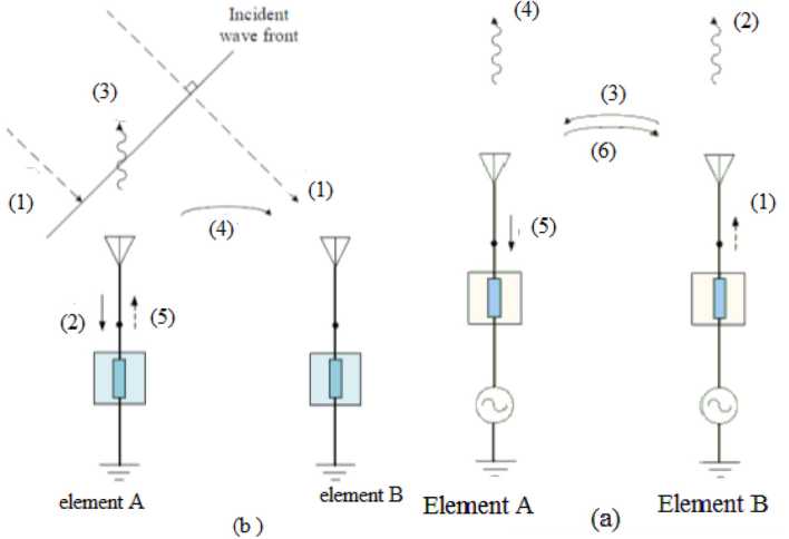
Fig. 1. Coupling effect of two-element
i.e., to decrease the re-scattered rays, so that the re-scattered wave is selected. ® and reflected wave ® cancel each other. The antenna element’s performance understudy can be investigated in the receiving mode deploying the excited aspect with the other 50-ohm component [3]. The main effects of MC on impedance patterns are presented in the following sections .
1. Mutual Impedance
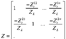
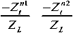
Antenna pattern radiation is strongly dependent on the impedance of antenna terminals. On the other hand, the antenna impedance of arrays is considerably different from an isolated antenna. The MC amongst the antenna arrays causes the impedance variation. Consider N -elements array, the matrix impedance is presented as:
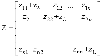
Where, Zmn is the self impedance if ( m = n ), and mutual impedances where, ( m ≠ n ) of the antennas and ZL is the impedance of the load. This matrix impedance represents the total impedance of the antenna terminals [7]. as expressed by:
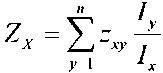
Where I p , is the p th antenna element terminal current. The impedance between x th and y th elements is Zx , y .
Generally, a square matrix represents the mutual impedance with an order similar to the array’s size. In comparison, the self-and mutual impedances of eq. (1) depends on the antenna array type and
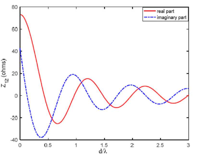
Fig. 2. The variation in mutual impedance of two parallel half-wavelength dipoles with the separation [8], mutual impedance, and MC decreases as the spacing between elements increases
Fig. 3. Mutual impedance variation for two, center-fed dipoles, with inter-element spacing are displayed structure. To evaluate the current pattern on the antenna surface, the projections of the impedances are mainly important. The variance of the space between the antenna components in the array influences MC. The alteration in the array elements’ inter-spacing contributes to the mutual impedance of the altered antenna elements. Figs. 2 and 3 reflect the inter-element spacing dependency of a two-element dipole array’s mutual impedance.
2. Steering Vector
The steering vector describes the response to the signal incidence of an array of antennas, and a mathematical formula can be used to express it. The steering vector primarily relies on the antenna’s unit’s direction, the spacing of the components, the radiation properties, and each incident wave’s component mode’s polarization. It is possible to use a direct calculation of complex array unit patterns to acquire an array’s steering vector; however, it is challenging. The MC across the components of an array thus influences the steering vector and, also, the array [9]. To establish the influence of MC [7], the array output was analyzed employing an Conventional steering vector (CSV). The MC influences were observed to be lower in the horizontal layer than in the vertical layer, where the distance among the components is larger than half the wavelength. Since coupling effects are not accounted for by the CSV, the voItages obtained should be accounted for to evaluate a functional series. Yuan et al. [5] suggested a strategy for specifically achieving the array manifold by applying the universal steering vector to manage this constraint (USV). In order to connect both the CSV and USV of a collection, the following relationships are provided.:
А“{в^ = \с.(е,фУ'^А‘{е,фУ\ (3) where [с^^У^г^Т^^)]
Where, A u and A c is the CSV and USV of the considered array, correspondingly, The transition millue is T, the matrix entry is Y, and the termination antenna impedance is ZL. The C matrix in eq. (3) is based on angle and polarization, including Gupta and Ksienski’s impedance matrix [2]. The impedance and even the phased array radiation pattern are altered by coupling between the components. This demonstrates that, in limited situations, an exact measurement of an array’s radiation pattern is possible if (1) an effective CSV compensation procedure is used. (2) In the estimation, using USV, which is clearly shown in Fig. 3 below. In the figure the USV is illustrated to perform a certain radiation pattern by sending the basic beam in the selected signal path (at 00) and consequently nullifies the jammer at 500.
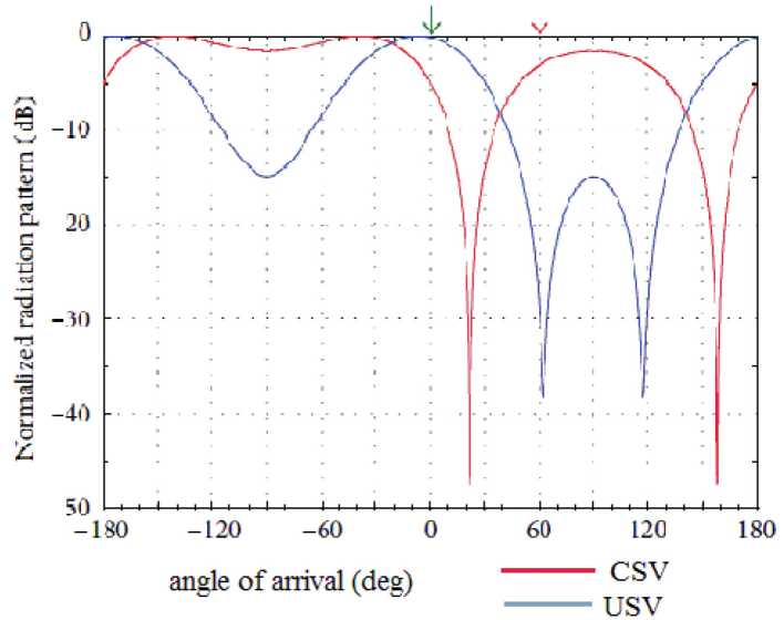
Fig. 4. 2-element dipole array pattern synthesized. Desired signal (green arrow): 0°○, 40dB; 1 jammer (red arrow): 60° and 0 dB
3. Radiation Pattern
Classical techniques such as pattern multiplication, numerical approaches (like multiple-input multiple-output systems MoM) [10], and active element pattern method [11]may use the coupling effect on the propagation of radiation on the pattern of radiation to research. For a particular array kind, a specific pattern analysis method is required to be dependent on several parameters; the kind array element desired space between the elements, size of array, and availability of the computation resources. The characteristics of the radiation of a given array, for instance, the input current at the terminals of the antenna is affected. A suitable antenna array is anticipated, and a cut off beam (nulls) conform to undesirable signals to generate a pattern that has its primary beam targeting the signal being required. Distributions of a significant low side lobe level (SLL) are also anticipated. Nevertheless, in the antenna pattern, standard pattern synthesis methods give rise to lower SLL, and isotropic properties of the components are assumed [12]. Although the MC effect is overlooked in the pattern synthesis, errors are caused in functional distribution situations. Enhancements have been suggested to resolve the distribution errors of the dipole array [13]. Two approaches, function mode and array mode have been established. To measure the array pattern, the distinctive model-based methodology reduces the orthogonal behaviors of distinctive modes. By this approach, volumetric modifications with complex computations are given. It is possible to use point fitting for the array modes that should not be orthogonal, to cope with this difficulty. These methods, along with some other methods applied previously in the literature, can be used to run both uniform and non-uniform arrays, with the need to express the array in the form of a time process matrix.
Accounts of the coupling impact, in a small array, voItages at the terminals of antenna (those with coupling) is Vc , and can be articulated in the sense of voItages (without Coupling Vn), and matrix coupling K is represented as [11]:
V c = KV n
compensation of the MC could be performed the reciprocal of the coupling is multiplied by matrix with V c :
V n = K -1 V c
For an array with a single-mode elements array, this process is quite simple; the compensation coupling matrix, K -1, does not depend on the scan. However, the scan-dependent coupling compensation is required for arrays with multimode elements. Large arrays’ efficiency could be estimated from the MC matrices of small arrays of a related lattice [14]. It is possible to predict the coupling matrix [15] using the Fourier decomposition of the calculated element patterns.
। Tilkd
mn ~ \
-л/ка
^^ Q-jnkdl,du ft")
is coupling coefficient, which is Fourier coefficients of the complex voItage patterns of the array elements (u). gm(u) is the voItage patterns of the array elements it is a complex function. And f i(u) is an isolated element. f i(u) is assumed being autonomous of zero voItage, and the inter-element spacing is greater than half-wavelength. This technique is applied on the unreciprocated antennas since it needs – 91 – the antennas to operate in a single-mode, transmitting or receiving that the inter-element spacing is greater than half-wavelength [16]. Further methods of compensation are presented in the following section.
4. Decoupling Method In Antenna Arrays
Researchers investigated many methods to compensate or eliminate the negative impacts of MC on antenna array performance. These methods’ efficiency is primarily based on the type of antenna and the application in which the arrays are used for. Common antenna arrays that have been used in communication systems are primarily characterized by Open-Circuit VoItage Method, S-Parameter Method, Receiving mutual impedance method, and Antenna Design.
5. Open-Circuit Voitage Method
The open-circuit voItage technique is a special way to decoupling magnetic resonance imaging (MRI) antenna arrays that need special attention. In parallel MRI, antenna arrays are important, which decreases the time span of the imaging process and improves the image signal-to-noise ratio (SNR) for imaging over wider regions. [17]. Antenna arrays in MRI demonstrate an important characteristic called phased arrays. As in common communication arrays, they accept signals in the near-field region rather than in the far-field range. The space between the inter-element is much smaller than those in ordinary arrays. These properties made MRI antenna arrays more considerable to the effects of pf MC. The signal processing circuits from the phased coil array and N output ports are equipped with N input ports., and they are determined by an impedance matrix in the circuit network. The input ports are connected signals to the decoupling network from the phased coil array, while these outputs are decoupled signals to the processing circuits from the decoupling network. In ordinary contact arrays, the coils in MRI are positioned even nearer in than the antenna elements. In phased MRI arrays, this issue is much more complicated.
6. Receiving Mutual Impedance Method
The mutual impedance method receives a more precise approach than the open-circuit voItage system. For MRI phased arrays, this approach is typically much more efficient. In this approach, the external source is taken into consideration. This is achieved by specifying the receiving reciprocal impedance, under which an additional source excites the current pattern on the exciting antenna. In MRI, the RF pulse’s active slice is the external basis for the phased array [18]. It was observed that MC could be absolutely terminated, and it was essential to receive coupling-free array signals. In a virtual MRI system only, these techniques are still constrained to theoretical observations or experimental tests. It should be remembered that the receiving mutual impedances need to be determined in situ with the MRI machine or estimated with the functional MRI machine for the most efficient application of the receiving mutual impedance system in MRI [19]. The divergence in the array manifold attributable to MC appears as a fault for subspace-based estimation algorithms that obstruct orthogonality between the covariance matrix signal and noise subspaces. In [15], where the genetic algorithm (GA) was employed to minimize the error to achieve a compensation matrix to restore the MUSIC algorithm's estimation efficiency, a related method was also employed. The recommended compensation strategy accomplishes faster convergence. Also, for every subspace-based parameter estimation algorithm, – 92 – the recommended approach is valid. A method of compensation is a more realistic method that only includes knowledge of the terminal voItages or currents. First, it tries to calculate and then eliminate the sum of MC from the calculated signal voItage. A modern principle of mutual impedance was developed to have the MC effect in a more skilled way, which he named the form of obtaining mutual impedance [11].
An antenna array consisting of n elements is known to represent the receiving mutual impedance method. Two external sources can be assumed to be stimulated by the voItage-induced on an antenna terminal load: Attributable to other antenna components in the array, the incoming signals and scattering area. The origin of the MC is the latter portion. Thus, the voItage, for instance, the antenna array can be inscribed through the kth antenna terminal load Vt as:
К = ZJt
= utk+z^ +
where ZL is the impedance of load, I* =(k = l,2,...n) represents the current on the kth antenna terminal load, U‘t is the voItage across the load as a result of the incoming signals with MC, and Zt (i=1,2,…k-1, k+1,.. n) is the new mutual impedance between the kth and the ith antenna elements. That part f If ++ ^f If + ^t If +Zf It , is the voItage arises from MC and it must be canceled from the terminal voItage to obtain ^t .
The mutual impedance Ztki should be determined to estimate the voItage introduces from the MC. The new mutual impedance Ztki in equation (7) indicates the ratio of the voItage produced across the load ZL of the kth antenna element to the exciting terminal current passing through the load ZL of the ith element. The second part on the right-hand side of eq. (7) which represents the voItage due to the MC effect, can be calculated. The preceding series of equations apply to each other in order to accommodate all elements in the sequence. v = [vtl,vt2,...v" matrix V) to the voItages generated from the signals alone и =
, ( T ) represents the transpose of the иЖ-и;] , therefore:
ZV=U
Once the impedance matrix of eq. (9) is determined, the terminal decoupled voItages U can be found from the calculated coupled voItages V. If R(t) denotes the voItage vector received at time t from the array which is also complex. Then
R(t) =s(t)T+m(t)T
Where s(t) is the time-dependent mode of V and voItage's complex vector is m (t). It is understood that the noise voItages on the antenna the terminals are entirely unrelated. To each other and the VoItages signal [20, 21] while accounting for the compensation of the MC influence of (8) and (9).
7. S-Parameter Method
In this method, an N-port network is used to model the receiving or transmitting antenna array and the scattering parameters used in modeling the MC effect between antenna elements of the array [22] . By determining the s-parameters, the coupled terminals signals can be used to measure the compensated signals. Nevertheless, this approach is notable in that only the transmission array is successfully modeled to enhance the phenomenon of MC [23] . As for the receiving array, The s-parameter antenna components need to be operated by an external power source connected to the terminal of one of the antennas in the array. The array whose antenna elements are all controlled by an external array fails to perform appropriately. The S-consequence parameter is that the MC is autonomous of the collapsed independent factor in the receiving array [24]. Therefore, this approach has the same coupling signal output as that of the open-circuit voItage method and therefore faces the same difficulties as the open circuit system [18] .
Conclusion
In this review paper, which the focus was on the analysis of the published work of the current literature, the major effects of MC were outlined on antenna parameters like impedance and radiation pattern in the present work. These works emphasized several models that are provided for deleting the efficiency drawbacks of MC. These methods perform compensation of MC convenient for specific types of antenna array elements.
References Mutual coupling enhancement in antenna array
- Ludwig A. Mutual coupling, gain and directivity of an array of two identical antennas, IEEE Transactions on Antennas Propagation, 24(6), 837–841, 1976.
- Gupta I. and Ksienski A. Effect of mutual coupling on the performance of adaptive arrays, IEEE Transactions on Antennas Propagation, 31(5), 785–791, 1983.
- Abedin M. J. and Mohan A. S. A subspace-based compensation method for the mutual coupling in concentric circular ring arrays for near-field source localisation, International journal of antennas propagation, 2012, 2012.
- Hui H. Compensating for the mutual coupling effect in direction finding based on a new calculation method for mutual impedance, IEEE Antennas Wireless Propagation Letters, 2, 26–29, 2003.
- Lui H. S. and Hui H. T. Mutual coupling compensation for direction-of-arrival estimations using the receiving-mutual-impedance method, International journal of Antennas Propagation, 2010, 2010.
- Craeye C. and González-Ovejero V. A review on array mutual coupling analysis, Radio Science, 46(02), 1–25, 2011.
- Balanis C. A. Antenna Theory Analysis and Design, John Wiley and Sons Inc,» Hoboken, New Jersey, 2005.
- Balanis C. A. Antenna theory analysis and design, A JOHN WILEY & SONS, Hoboken, New Jersey, Inc., Publication, 2005.
- Wax M. and Sheinvald J. Direction finding of coherent signals via spatial smoothing for uniform circular arrays, IEEE transactions on antennas propagation, 42(5), 613–620, 1994.
- Chen X., Zhang S. and Li Q. A review of mutual coupling in MIMO systems, Ieee Access, 6, 24706–24719, 2018.
- Kelley D. F. and Stutzman W. L. Array antenna pattern modeling methods that include mutual coupling effects, IEEE Transactions on antennas propagation, 41(12), 1625–1632, 1993.
- Zhang X. and Webb A. Design of a capacitively decoupled transmit/receive NMR phased array for high field microscopy at 14.1 T, Journal of Magnetic Resonance, 170(1), 149–155, 2004.
- Kang Y.-W. and Pozar D. Correction of error in reduced sidelobe synthesis due to mutual coupling, IEEE transactions on antennas propagation, 33(9), 1025–1028, 1985.
- Karimkashi S. and Kishk A. A. Focused microstrip array antenna using a Dolph-Chebyshev near-field design, IEEE Transactions on Antennas Propagation, 57(12), 3813–3820, 2009.
- Steyskal H. and Herd J. S. Mutual coupling compensation in small array antennas, IEEE Transactions on Antennas Propagation, 38(12), 1971–1975, 1990.
- Singh H., Sneha H. and Jha R. Mutual coupling in phased arrays: A review, International Journal of Antennas Propagation, 2013, 2013.
- Lee R. F., Giaquinto R. O. and Hardy C. J. Coupling and decoupling theory and its application to the MRI phased array, Magnetic Resonance in Medicine: An Official Journal of the International Society for Magnetic Resonance in Medicine, 48(1), 203–213, 2002.
- Hui H. T. An effective compensation method for the mutual coupling effect in phased arrays for magnetic resonance imaging, IEEE transactions on antennas propagation, 53 (11), 3576–3583, 2005.
- Friedlander B. and Weiss A. J. Direction finding in the presence of mutual coupling, IEEE transactions on antennas propagation, 39(3), 273–284, 1991.
- Fredrick J. D., Wang Y. and Itoh T. Smart antennas based on spatial multiplexing of local elements (SMILE) for mutual coupling reduction, IEEE Transactions on Antennas Propagation, 52(1), 106–114, 2004.
- Farahani H. S., Veysi M., Kamyab M. and Tadjalli A. J. I. a. Mutual coupling reduction in patch antenna arrays using a UC-EBG superstrate, IEEE antennas wireless propagation letters, 9, 57–59, 2010.
- Wallace J. W. and Jensen M. A. Mutual coupling in MIMO wireless systems: A rigorous network theory analysis, IEEE transactions on wireless communications, 3(4), 1317–1325, 2004.
- Qian Y., Deal W. R., Kaneda N. and Itoh T. A uniplanar quasi-Yagi antenna with wide bandwidth and low mutual coupling characteristics, in IEEE Antennas and Propagation Society International Symposium. 1999 Digest. Held in conjunction with: USNC/URSI National Radio Science Meeting (Cat. No. 99CH37010), 1999, 2: IEEE, 924–927.
- Li Q., Feresidis A. P., Mavridou M. and Hall P. S. Miniaturized double-layer EBG structures for broadband mutual coupling reduction between UWB monopoles, IEEE Transactions on Antennas Propagation, 63(3), 1168–1171, 2015.
