Neural Network Synchronous Binary Counter Using Hybrid Algorithm Training

Author: Ravi Teja Yakkali, N S Raghava
Journal: International Journal of Image, Graphics and Signal Processing(IJIGSP) @ijigsp
Article in issue: 10 vol.9, 2017.
Free access
Information processing using Neural Network Counter can result in faster and accurate computation of data due to their parallel processing, learning and adaptability to various environments. In this paper, a novel 4-Bit Negative Edge Triggered Binary Synchronous Up/Down Counter using Artificial Neural Networks trained with hybrid algorithms is proposed. The Counter was built solely using logic gates and flip flops, and then they are trained using different evolutionary algorithms, with a multi objective fitness function using the back propagation learning. Thus, the device is less prone to error with a very fast convergence rate. The simulation results of proposed hybrid algorithms are compared in terms of network weights, bit-value, percentage error and variance with respect to theoretical outputs which show that the proposed counter has values close to the theoretical outputs.
Artificial Neural Networks, Hybrid Algorithms, Synchronous Binary Counter, Back Propagation Algorithm, Evolutionary Algorithms
Short address: https://sciup.org/15014236
IDR: 15014236
Text of the scientific article Neural Network Synchronous Binary Counter Using Hybrid Algorithm Training
Published Online October 2017 in MECS
Artificial Neural Networks and evolutionary algorithm techniques have been used in finding optimum solutions for many engineering applications ranging from wireless communication [1], pattern recognition to medical applications [2,31-32]. Efforts have been made to improve performance of Logic Circuits in applications of Satellite Communication, medical applications and radiation prone environment [3-5], where the devices are exposed to a huge amount of noise and distortion with a very low signal power but we still require precise and accurate signals with fast output. So in order to address these issues, we have used Neural Network as the basic building block for the design of Synchronous Counter. Neural Networks find applications in critical and sensitive environments [6]. The advantage of using Neural Network is that they learn by example and also can adapt to various environments [7-9], because of the availability of robust training algorithms, their precision, accuracy can be controlled and data processing by the Neural Network can result in faster output due to their parallel processing nature which can be used in the design of highly reliable and fast logic circuits.
Many applications of Neural Networks have been proposed in Digital Circuits. A Neural Network has been used for Digital Signal Processing in [10] and they are also used in their fault diagnosis [11-12]. Cantonese Speech Recognition was done using Neural Network logic gate Circuit (AND, OR, NOT) which was trained using Genetic Algorithm [13]. Hopfield neural networks were used for the design of AND Circuit, the full adder, D-Latch with 4-Bit Shift Register and 4-Bit Asynchronous counter [14]. A Binary Logical Neural Network was constructed [15] in which activation function of each neuron was a combinational logic gate. Fault and radiation analysis, which involves creating a replica of original digital circuit using Neural Network, is done in [16]. A Bi-stable Memory Device and Binary Counters were created using Spiking Neural Networks in [17].
Genetic algorithm is metaheuristic algorithm based on natural selection of human beings. Particle Swarm Optimization is inspired by the movement of organisms in a bird flock [18]. Artificial Bee Colony algorithm is a swarm intelligence algorithm [19] based on the intelligent foraging behavior of honey bees. Back Propagation Algorithm [20] is applied to multilayer feed-forward Neural Net with continuous Activation Function [21]. Since, Binary Sigmoid Function [22] is used for binary input for computation of output, so back-propagation algorithm is well suited for our application. Even though evolutionary algorithms can be used to find a global optimized solution but these algorithms are unable to find a local optimized solution because of the creation of a large solution space in training neural network weights [23] and their subsequent evaluation process while back propagation algorithm is often stuck at a local best solution.
Hybrid algorithms have gained insight in giving better solutions for many engineering applications. A Hybrid Genetic Algorithm with hyper mutation and elitist strategy has been applied to design of Automated Analog Circuit [24], a hybrid PSO for Medical Image Registration [25] and hybrid ABC algorithm with a LM algorithm for training Neural Networks in [26]. Also, Genetic algorithm has been used to design reconfigurable hardware in [6, 27] using ANN which adapts its hardware according to the environment. A hybrid variant of particle Swarm Optimization and Back Propagation Algorithm which involves PSO searching a globally optimal solution and after that, BP is searching for a locally optimal solution has been applied in [23] for training feed forward ANN in application of Iris recognition, function approximation and three bits parity problem.
But some of the hybrid algorithms also have some limitations. A hybrid algorithm which involves GA finding optimized weights after learning from Back Propagation Algorithm is presented in [28], but suffers from the problem that BP first finds a locally optimal solution and GA optimization after that may not be the best solution as solution space is restricted to a small range of values. A hybrid version of the algorithm combined with BP has been implemented [29-30] for feed forward neural Network Training but the variant of ABC-BP in [29] is computationally expensive as we have to apply the BP algorithm on every habitat generated by Artificial Bee Colony Algorithm.
In order to address these issues, we have employed the model similar to the one used in [23] in which instead of initializing the weights randomly as in case of the Back Propagation algorithm, first a globally optimal solution is found using Genetic, Particle Swarm Optimization, Artificial Bee Colony Algorithms and then a local search is performed on best solution obtained from these using the back propagation algorithm. The algorithm ensures a faster convergence rate and a better optimal solution.
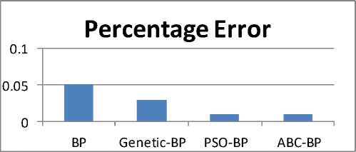
The aim of the paper is to apply hybrid training algorithms; Genetic, particle swarm optimization and artificial bee colony with back propagation learning for training the feed forward networks used in the implementation of 4-Bit Binary Synchronous Neural Network counter considering a multi objective fitness function. The hybrid algorithms can result in a faster convergence rate and a better optimal solution. Also, using the neural networks in designing digital circuit design can give accurate outputs because of availability of robust training algorithms, adaptability to various environments, can change circuit connections even after deployment and their parallel processing nature can result in faster computations of data. Simulation results show that the hybrid algorithms perform better than BP learning algorithm in terms of fitness function value, mean variance, mean percentage error, output bit value at level ‘0’ and level ‘1’. Also the using the neural network, the counter has output values close to ideal values.
The remainder of the paper is organized as follows. Section II briefly describes the Proposed Design, Section III the proposed algorithms and Section IV presents the hybrid algorithms used in training the neural network. Section V shows the simulation results of the proposed counter, its applications in design of the decade and pulse counter and finally, Section VI shows the conclusion.
-
II. Proposed Design
In this section, a brief illustration of the digital design used in the Counter is presented. At each step of computing the output of the neuron, binary sigmoid function [22] was utilized given by the formula:- y — 1/(1 + exp(-Z)) (1)
y — Output of Logic Function
Z — Weighted Sum of Input
-
A. NAND GATE (Lower Level)
All the Combinational logic Gates and flip-flops were implemented using NAND Gate. Fig-1 shows the design of the simulated NAND gate and Table-1 shows the truth table. The interconnection weights are decided according to the error tolerance of a specific application.
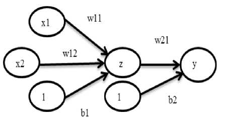
Fig.1. Design of the 2 Input NAND Gate with bias b1, b2 and weights w11, w12, w21 adjusted according to the error tolerance
-
B. Negative Edge Triggered D-Flip Flop Model (MidLevel)
A Negative Edge triggered D-Flip Flop was simulated using the master-slave flip flop configuration and the design changes its state at the negative edge of the clock. Since neurons can fire asynchronously, so even if some of them delay their output, then also Master Slave Flip Flop can respond if the time period of clock is more than the delay. Table-2 shows the State change assignment and Fig.2 shows the implementation of D-Flip Flop using NAND Gate and Figure.3 shows the negative edge triggered flip flop using Master Slave Design.
-
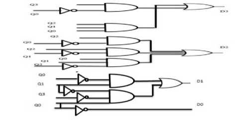
C. Binary Synchronous Counter (Top-Level)
Top-Down Design Methodology was used for implementing the required Counter Starting from the Logic Gates with subsequent upper levels of abstraction. Figure 4a and 4b shows the Digital Circuit Design of Up and Down Counter. The Boolean equations for the inputs of D-flip Flop for Up Counter are shown below:-
D 3 — Q 3 © ( Q 2 • Q i * Q 0) (2)
D 2 = Q 2 Ф (Q1 • Q 0)
D1 = Q1Ф Q 0
D 0 =~ Q 0
Where “ • ” indicates an AND operation, “ Ф ” indicates an Exclusive-OR operation and “~” indicates a NOT Operation. Boolean Equation inputs of D-Flip Flop for Down Counter are shown below:-
D3 = Q30 (Q2 + Q1 + Q0)
D2 = Q20 (Q1 + Q0)
D1 = Q1D Q0
D0 =~ Q0
Where “ + ” indicates an OR operation, “ □ ” indicates an Exclusive-NOR operation
Table.1. Truth Table of Simulated NAND Gate
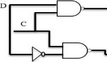
Fig.2. NAND Gate Implementation of level Triggered D-Flip Flop
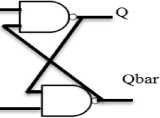
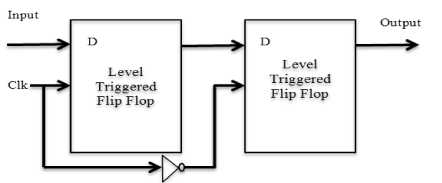
Fig.3. Negative Edge Triggered D-Flip Flop using Master Slave Flip Flop Configuration
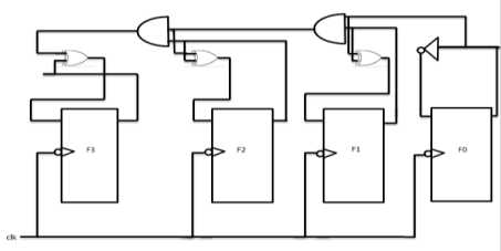
Fig.4a. Design of Up-Counter using Neural Negative Edge D-Flip Flops and logic gates
|
BP Only Algorithm |
|||
|
x1 |
x2 |
B |
y=F(z) |
|
0 |
0 |
1 |
0.9997 |
|
0 |
1 |
1 |
0.9994 |
|
1 |
0 |
1 |
0.9995 |
|
1 |
1 |
1 |
4.0714e-04 |
|
GA-BP Algorithm |
|||
|
x1 |
x2 |
B |
y=F(z) |
|
0 |
0 |
1 |
0.9999 |
|
0 |
1 |
1 |
0.9997 |
|
1 |
0 |
1 |
0.9998 |
|
1 |
1 |
1 |
1.705e-04 |
|
PSO-BP Algorithm |
|||
|
x1 |
x2 |
B |
y=F(z) |
|
0 |
0 |
1 |
0.9999 |
|
0 |
1 |
1 |
0.9999 |
|
1 |
0 |
1 |
0.9999 |
|
1 |
1 |
1 |
4.0729e-04 |
|
ABC-BP Algorithm |
|||
|
x1 |
x2 |
B |
y=F(z) |
|
0 |
0 |
1 |
0.9997 |
|
0 |
1 |
1 |
0.9994 |
|
1 |
0 |
1 |
0.9995 |
|
1 |
1 |
1 |
4.18041e-04 |
Table.2. State Change Assignment of Simulated Negative Edge Triggered Neural Network D-Flip Flop.
|
BP-Only Algorithm |
||
|
Q n |
D |
Q n+1 |
|
0 |
0 |
4.0770e-04 |
|
0 |
1 |
0.9994 |
|
1 |
0 |
4.0785e-04 |
|
1 |
1 |
0.9997 |
|
GA-BP Algorithm |
||
|
Q n |
D |
Q n+1 |
|
0 |
0 |
1.7072e-04 |
|
0 |
1 |
0.9997 |
|
1 |
0 |
1.7078e-04 |
|
1 |
1 |
0.9999 |
|
PSO-BP Algorithm |
||
|
Q n |
D |
Q n+1 |
|
0 |
0 |
4.8039e-04 |
|
0 |
1 |
0.9999 |
|
1 |
0 |
8052e-04 |
|
1 |
1 |
0.9999 |
|
ABC-BP Algorithm |
||
|
Q n |
D |
Q n+1 |
|
0 |
0 |
1.8102e-04 |
|
0 |
1 |
0.9996 |
|
1 |
0 |
1.82006e-04 |
|
1 |
1 |
1.0000 |
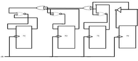
Fig.4b Design of Down-Counter using Neural Negative Edge D-Flip Flops and logic gates
-
III. Proposed Algorithms
A brief overview of the hybrid algorithms which are used in the training are presented in this section. Since, NAND Gate has been employed as the basic building block so; hybrid algorithms are applied for adjusting the weights of the NAND gate.
A multi-objective fitness function was used in each algorithm which takes into account the following quantities:-
-
1) The error term between the expected output and the theoretical output
-
2) The magnitude of the weights, as large values of the weights will result in the expensive connections for interconnection in a neural net
-
3) A constant term is added so that any particular term doesn’t contribute more to the fitness function if the value of the denominator is very less.
The fitness function used in hybrid algorithm is given below:- f = 1 / (K1 + K 2* ^ abs (T (j) - Y (j)) + K 3* ^ abs (Weights))
K1, K2, K3=Parameters decided according to application
T (j) =Theoretical Output, Y (j) =Experimental output
Weights =Weights of NAND gates
-
A. Hybrid Genetic-BP Algorithm
Genetic algorithm finds a globally optimal solution and BP algorithm further improves the solution using its local search. In this algorithm, an initial population with random weights is created, each individual representing a complete solution. A Fitness value for each habitat is calculated based on equation 10; the individual with greatest fitness value is stored. Using available population, subsequent better population is created using “Uniform Crossover Migration” and “Interchanging mutation”. In Uniform crossover, a random vector is created with an entry of 0’s and 1’s. The Value from the 1st vector weight is taken when an entry in random vector is “1” while entry from 2nd vector weight is taken if entry in random vector is “0”. Fig.5a shows an example of uniform crossover. Fig.5b shows the detailed algorithm used in our design.
|
W11 (1) |
W12 (1) |
b1 (1) |
W21 (1) |
B21 (1) |
|
First Vector |
||||
|
W11 (2) |
W12 (2) |
b1 (2) |
W21 (2) |
B2 (2) |
|
Second Vector |
||||
|
1 |
1 |
0 |
1 |
0 ) |
|
Random Vector || |
||||
|
W11 (1) |
W12 (1) |
b1 (2) |
W21 (1) |
B2 (2) |
Crossover Vector
Fig.5a. Uniform Crossover Operation in Genetic Algorithm
-
B. Hybrid Particle Swarm Optimization-BP Algorithm
A hybrid variant of particle swarm optimization with BP is used to find the optimal weights for Neural Network. In this algorithm, an initial population of particles is created with each particle representing the solution of given problem. Then, a velocity of each particle is set in the range of maximum and minimum value of weights. Parameters for equation 11 and 12 are set. The fitness value of each particle is calculated based on equation 10. The algorithm is iterated for a number of rounds where each particle is improved based on its local best and global best solution of equation 11, 12 and 13.
v(i) = v(i) + sp * rp * (localbestweight(i) - weight(i))
v(i) = v(i) + sg * rg * (globalbestweight - weight(i))
weight (i) = weight (i) + v (i)(13)
Weight(i) =Current Particle i v(i) =velocity of ith particle sg =Parameter for change of particle based on global best sp = Parameter for change of particle based on local best rg= random value between 0 and 1
rp = random value between 0 and 1
After the maximum iterations are reached, a global best solution is passed to back propagation algorithm. Fig.6 shows the detailed view of PSO algorithm used in our design.
Genetic Algorithm
Initialization: Generate N habitats containing value of NAND Gate Weights.
Population Evaluation: Calculate Fitness value for each individual.
Store individual with greatest fitness
For i= 1:Total_Habitats r=Generate random number either 0 or 1
For every weight j
If r==1
Weights (i, j) = Choose jth weight from fittest indivdual
Else
Weights (i, j) = Choose jth from ith vector
End If
Calculate Fitness value of this new Habitat and store it in crossover vector
End For
Calculate Fitness value for each individual of crossover vector
Store individual with greatest fitness
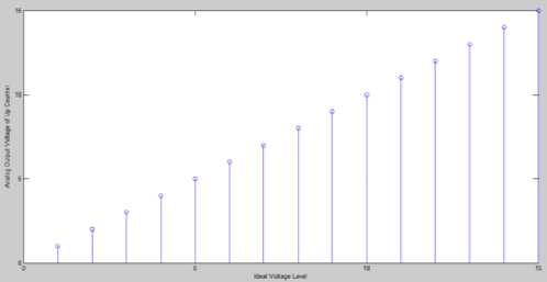
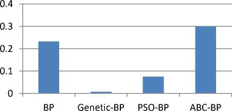
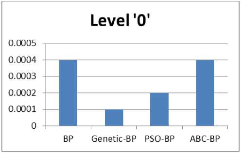
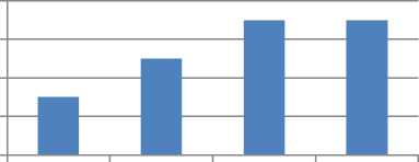
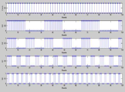
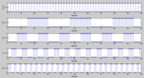
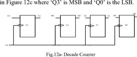
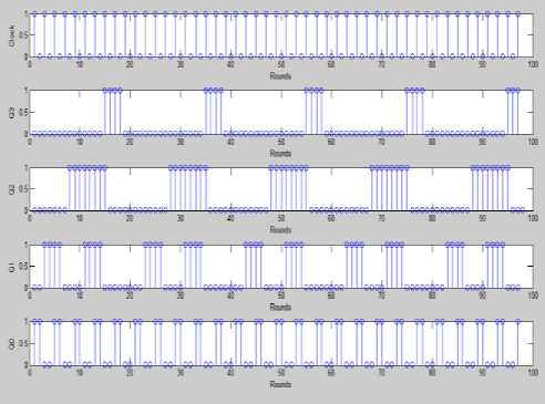
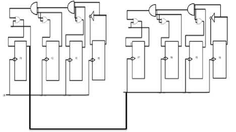
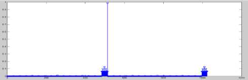
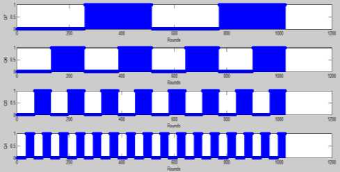
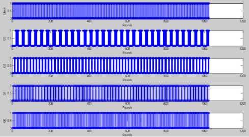
IF (fitness of best after crossover Perform Mutation End IF return fittest individual which will be passed to bp algorithm. Fig.5b. Hybrid Genetic Algorithm Particle Swarm Optimization Algorithm Initialization: Generate N particles containing NAND Gate Weights. Initialize velocity for each particle with random value. Set parameters: sp=0.9, sg=0.3 Population Evaluation: Calculate Fitness for each particle and place it as t l_weights . Find the solution with greatest fitness and place it in global best g_weights. While t < max iteration For i= 1: Total Particles Rp =Generate Random Number between 0 and 1 Rg = Generate Random Number between 0 and 1 For every weight j Velocity (i, j) = Velocity (i, j) +sp*rp*(l_weights(i, j)-weight(i, j)) Velocity (i, j) = Velocity (i, j) +sg*rg*(g_weights (j)-weight (i, j)) Weight (i, j) =Weight (i , j) +Velocity (i, j) End for Calculate Fitness value of this new Habitat IF (fitness of new habitat >fitness of local best) Replace local best with current vector End IF IF (fitness of new habitat >fitness of global best) Replace Global best with current vector End IF End For t=t+1; End while Return Fittest Individual. Fig.6. Hybrid Particle Swarm Optimization C. Hybrid Artificial Bee Colony-BP Algorithm ABC is combined with Back propagation in [5] and [22] for feed forward neural network training. An initial population of bees is created. The Fitness value of each bee is calculated using equation 10 and bee with best fitness is stored. The Algorithm is iterated for a few rounds and each bee is changed using equation 14. After the maximum rounds are reached, individual with greatest fitness is passed to the BP algorithm. Fig.7 shows the detailed view of the algorithm used in our design Algorithm. V(i) = Weight(i) + r * (Weight(i) - Weight(j)) (14) V(i) =New Solution, Weight(i) =Current Weight r =random number between -1 and 1. Weight(j)=Weight of jth solution chosen randomly between available habitats. D. Back Propagation Algorithm Evolutionary algorithms make sure that the solution has a very fast convergence rate after they are passed to the BP algorithm. Weights w11, w12, w21 and bias b1, b2 are adjusted for a few iterations with a variable learning rate given by equation 15. Fig 8a shows the BP algorithm and Fig 8b flowchart of the proposed BP algorithm. A variable learning rate was employed for training Neural Net which decreases as the number of rounds increases with time:- a = 1/ (K + r) K=Parameter whose value is fixed based on application R=No of rounds completed Artificial Bee Colony Algorithm Initialization: Generate N habitats containing value of NAND Gate Weights. Population Evaluation: Calculate Fitness value for each individual. Store individual with greatest fitness While t < max iteration For i= 1: Total Habitats V (i) =0; r=Generate random number between -1 and 1 j= Generate random integer between 1 and total habitats. For every weight k V (i, k) = Weight (i, k) + r*(Weight (i, k)-Weights (j, k)); End for Calculate Fitness value of this new Habitat IF (fitness of new habitat >fitness of current habitat) Replace ith vector with vector V (i) End IF End For t=t+1; End while Fig.7. Hybrid Artificial Bee Colony Algorithm Fig.8a. Flowchart of Hybrid Back Propagation Algorithm Back Propagation Algorithm Initialization: Initialize all weights to evolutionary algorithm output. Set learning rate α=0.2. Evaluation: For i= 1: max iteration For each training pair x1 (j), x2 (j) and output t (j) Zin (j) = w11*x1(j) + w12*x2 (j) +b1 Calculate Output of Hidden Layer: Z (j) =1/ (1+exp (-Zin (j))) Compute net output signal for output layer: Yin (j) = w21*Z (j) + b2 Calculate Output of Output Layer: y (j) =1/ (1+exp (-Yin (j))) Compute error correction factor delta: δ (j) = (t (j)-y (j))*(exp (-Yin (j))/(1+exp (-Yin (j)))^2) Find Weight adjustment for each output unit: w21(new)=w21(old) + α*δ(j)*z(j) ; b2(new)=b2(old)+ α* δ(j) Compute net error term for each unit of hidden layer δin11= δ (j)*w11 δin12= δ (j)*w12 δinb1= δ (j)*b1 δ11= δ in11*(exp (-Zin (j))/ (1+exp (-Zin (j))) ^2) δ12= δ in12*(exp (-Zin (j))/ (1+exp (-Zin (j))) ^2) δb1= δ inb1*(exp (-Zin (j))/ (1+exp (-Zin (j))) ^2) Find the Final Weights for each hidden unit w11 (new) =w11 (old) + α*δ11*x1(j) w12 (new) =w12 (old) + α*δ12*x2(j) b1 (new) =b1 (old) + α*δb1 End For End For Return Values of weights which will be used by NAND Gate Fig.8b. Hybrid Back-Propagation Algorithm IV. Simulation results The proposed Neural Network Counter was simulated in MATLAB IDE, running on a Windows PC with Intel Core i5 processor at 3.10 GHz. Table-3 shows the fitness values of each hybrid algorithm calculated using equation 10. The performance of the hybrid algorithms is compared with the ideal value which shows GA-BP performs better than other algorithms followed by PSO-BP, ABC-BP and BP. Table-4 and Figure-9 show the Analog output voltage with each algorithm. Each of the proposed algorithms has very close values to the theoretical output values of ideal counter. Fig 10a, 10b, 10c and 10d shows the percentage error, variance, bit value of logic ‘0’ and bit value of logic ‘1’ corresponding to BP, GA-BP, PSO-BP and ABC-BP. Table-5 shows the percentage error of counter with respect to theoretical values. GA-BP and PSO-BP outperform BP and ABC-BP with respect to mean percentage error and a very less variance. GA-BP gives slightly better performance than PSO-BP. Fig.9. Analog Output Voltage Corresponding to Digital Output of Up-down counter converted using ideal adc. Fig.10a. Graph of Percentage Error of Counter in each algorithm Variance Fig.10b. Graph of Variance in each algorithm Fig.10c. Output of each algorithm at logic level ‘0’ of Counter. 0.9998 0.9996 0.9994 0.9992 Level '1' BP Genetic-BP PSO-BP ABC-BP Fig.10d. Output of each algorithm at logic level ‘1’ of Counter. Table 3. Fitness value of best case solution for each algorithm based on equation -10 Algorithm Fitness Back Propagation 0.4982 Genetic-BP 0.4985 Particle Swarm Optimization-BP 0.4983 Artificial Bee Colony-BP 0.4982 Ideal Value 0.5 Table 5. Percentage Error and Variance of Analog Output Voltage with respect to theoretical values for BP, GA-BP, PSO-BP and ABC-BP Algorithm Binary Up-Down Up-Down Up-Down Up-Down Number Counter Counter Counter Counter using BP using GA- using using Algorithm BP PSO-BP ABC-BP Algorithm Algorithm Algorithm 0000 0 0 0 0 0001 0.51 0.11 0.27 0.55 0010 0.21 0.035 0.12 0.25 0011 0.11 0.01 0.07 0.15 0100 0.06 0.025 0.045 0.1 0101 0.03 0.01 0.030 0.07 0110 0.01 0.015 0.020 0.05 0111 0.004 0.018 0.0128 0.0357 1000 0.015 0.021 0.0075 0.025 1001 0.023 0.023 0.0033 0.0166 1010 0.030 0.025 0 0.01 1011 0.035 0.026 0.0027 0.0045 1100 0.040 0.027 0.0050 0 1101 0.043 0.028 0.0060 0.0030 1110 0.047 0.029 0.0085 0.0071 1111 0.050 0.03 0.010 0.010 Mean 0.0729 0.0258 0.0382 0.0802 Variance 0.2334 0.0085 0.0763 0.2981 Table 4. Analog Output Voltage for each algorithm converted using an Ideal ADC Binary Number 0000 Up-Down Counter using BP Algorithm 0.006 Up-Down Counter using GA-BP Algorithm 0.00015 Up-Down Counter using PSO-BP Algorithm 0.00030 Up-Down Counter using ABC-BP Algorithm 0.0006 0001 1.0051 1.0011 1.0027 1.0055 0010 2.0042 2.0007 2.0024 2.005 0011 3.0033 3.0003 3.0021 3.0045 0100 4.0024 3.9999 4.0018 4.0004 0101 5.0015 4.9995 5.0015 5.0035 0110 6.0006 5.9991 6.0012 6.003 0111 6.9997 6.9987 7.0009 7.0025 1000 7.9988 7.9983 8.0006 8.0002 1001 8.9979 8.9979 9.0003 9.001 1010 9.997 9.9975 10 10.001 1011 10.996 10.997 10.999 11 1100 11.995 11.996 11.999 12 1101 12.994 12.996 12.999 12.999 1110 13.993 13.995 13.998 13.99 1111 14.992 14.995 14.998 14.998 Fig.11a. Wave-Forms for each Bit of Down-Counter and its change with clock. Fig.11b. Wave-Forms for each Bit of Up-Counter and its change with clock A) Timing Analysis In this subsection, Timing analysis of each component is performed in MATLAB IDE. Timing Analysis of each component was performed with respect to NAND gate which was assumed to have a Unit delay. Table 6 shows the delay of each of the components. Table 6. Delay Values of each component with initial assumption of NAND gate delay. Component Delay Value NAND Gate 1 NOT Gate 1 OR Gate 2 AND Gate 2 XOR Gate 4 XNOR Gate 4 Level triggered D Flip Flop 3 Edge Triggered D Flip Flop 3 Up Counter 13 Down Counter 14 B) Application Simulation The proposed Neural Network Synchronous Counter was used in the design of:- I) Decade Counter Decade Counter is used in many applications in Embedded Systems and Digital Electronics especially for the design of the hardware timing circuits. Also, they are used as frequency divider where they provide a clock to microprocessors. The Diagram of the proposed Decade Counter is shown in Figure.12a and Figure.12b. It was simulated for about 100 Rounds with clock as the input. The simulation results of the counter are shown Fig.12b-Waveform of each bit of Decade Counter Fig.12c- Inputs to the Flip Flops for Decade Counter II) 8-Bit Pulse Counter Pulse Counter is used in timing circuits of embedded systems where they are mostly used to trigger interrupts. 8-bit pulse counter was implemented using a cascade of two 4-bit synchronous counters. An overflow flag ‘z’ is also set when the number of pulses reaches the maximum count. Diagram of the Pulse Counter has been shown in fig.13a. As we can see from the Fig.13a, the output Q3 of first stage serves as the clock input to the next stage. 13c shows the MSB’s from ‘Q7’ to ‘Q4’ with ‘Q3’ as clock and figure 13d shows the LSB’s from Q3 to Q0. Fig.13a. 8-Bit Pulse Counter by cascade of two 4-bit Counters Fig.13b- Waveform of overflow Flag ‘z’ of the pulse counter with some glitches introduced by neural network circuit. Fig.13c- Waveform of MSB from Q7 to Q4 with Q3 as clock to second 4-Bit Counter of 8-Bit pulse counter. Fig.13d- Waveform of LSB from Q3 to Q0 with clock to first 4-Bit Counter of 8-Bit pulse counter. Table.7- Parameters and Initial Assumptions in Research Paper 1.Weights Minimum Maximum w11 -25 25 w12 -25 25 b1 -25 25 w21 -25 25 b2 -25 25 2.Fitness Parameters(10) Value K1 2 K2 1 K3 10-4 3.Genetic Algorithm Habitats(N) 100 4.PSO Algorithm Habitats(N) 100 sp 0.9 sg 0.3 Max Iterations 10 5.BP Algorithm K1(15) 5 V. Conclusion In this paper, a 4-Bit Negative Edge Triggered Binary Synchronous Up-Down Counter has been designed using Artificial Neural Networks. It is trained with hybrid variants of ABC, PSO and Genetic Algorithm combined with Back Propagation algorithm using a multi-objective fitness function. The effectiveness of the proposed algorithms was shown by extensive experiments and it can be concluded that the use of hybrid algorithms (GA-BP, PSO-BP and ABC-BP) outperform learning algorithms in terms of fitness function value, percentage error and variance with respect to theoretical values. The output values of the Counter were very close to ideal values with very less percentage error. Two applications, namely a Decade counter and 8-bit pulse counter were also simulated.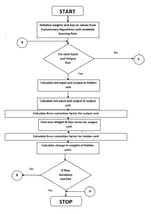
References Neural Network Synchronous Binary Counter Using Hybrid Algorithm Training
- A. Patnaik, D. E. Anagnostou, R. K. Mishra and Christodoulou CG, “Applications of Neural Networks in Wireless Communication”, IEEE Antennas and Propagation Magazine, Volume: 46, Issue: 3, 3 June, 2004 pp. 130-137.
- W. J. Lee, D. S. Kim, S. W. Kang and W. J. Yi, “Material depth reconstruction method of multi-energy X-ray images using Neural Networks”, Engineering in Medicine and Biology Society (EMBC), 2012 Annual International Conference of the IEEE, Volume:33 , Issue:5,28,Aug-Sep.1998, pp. 1514-1517.
- R. Garg, N. Jayakumar, S. P. Khatri and G. S. Choi, “Circuit Level Design Approaches for Radiation-Hard Digital Electronics”, IEEE Transactions on Very Large Scale Integration (VLSI) Systems,Volume:17, Issue:6,June,2009 pp. 781-791.
- C.Melear, “Control of Electromagnetic radiation in Digital Circuits”, Wescon Conference Proceedings, 4-6 Nov 1997, pp. 208-218.
- C.D Boloes, B.E Boser, B.H Hasegawa and J.A Heanue, “A multimode digital detector for solid-state medical imaging”, IEEE Journal of Solid-State Circuits, 1991 Volume:33, Issue:5, May.1998 pp.733-742.
- Parisa Soleimani, Reza Sabbaghi-Nadooshan, Sattar Mirzakuchaki, and Mahdi Bagheri,“Using Genetic Algorithm in the Evolutionary Design of Sequential Logic Circuits”, International Journal of Computer Science Issues(IJCSI), Vol. 8, Issue 3, May 2011, pp.1-7.
- K. Otsu , A. Ishiguro ,A. Fujii, T. Aoki and P. Eggenberrer, “Evolving an Adaptive Controller for a quadrupled-robot with dynamically arranging Neural Networks”, IEEE/RSJ International Conference on Intelligent Robots and Systems, Proceedings, Volume: 4, 2001, pp. 2036-2044.
- J. Dheeba and A. Padma,“Intelligent Adaptive Noise Cancellation using Cascaded Correlation Neural Networks”, International Conference on Signal Processing, Communications and Networking (ICSCN '07), 22-25 Feb,2007 pp. 178-182.
- T. P.Nam, Hue Ind. Coll, D. T. Viet and L. Van Ut, “Application of neural network in voltage stability assessment in real-time power market”, IPEC, Conference on Power & Energy, 12-14 Dec, 2012, pp. 196-200.
- D. P. Sharma, “Neural Network Simulation of Digital Circuits”, International Journal of Computer Applications, Vol.79 No.6, October 2013, pp. 7-13.
- Hisayuki Tatsumi, Yasuyuki and Shinji Tokumasu, “Logic Circuit Diagnosis using Neural Networks”, 31st International Sympsonium Multivalued Logic, 2001, pp.345-350.
- Zhouxun and Wangxiaoli, “Hybrid Artificial Bee Colony Algorithm for neural network training”, 24th Chinese Control and Decision Conference (CCDC), 23-25 May, 2012, pp. 2297-2299.
- H. K. Lam and Frank H. F. Leung, “Design and training for Combinational Neural-Logic Systems”, IEEE transactions on Industrial Electronics, October 2007, Vol. 54, No.1, pp.612-619.
- Hiroshi Ninomtya, Kunitaka EGAWA, Takeshi Kamio and Hideki Asai, “Design and Implementation of Neural Network Logic Circuits with Global Convergence”, IEEE International Conference on Neural Networks, 1996, Vol.22, pp. 980-985.
- Dipayan Bhadra, Tanvir Ahmed Tarique, Sultan Uddin Ahmed, Md. Shahjahan and Kazuyuki Murase, “ An Encoding Technique for Design and Optimization of Combinational Logic Circuit”, Proceedings of 13th International Conference on Computer and Information Technology (ICCIT 2010), 23-25 December, 2010, Dhaka, Bangladesh, pp. 744-750.
- Zeynab Mirzadeh, Jean-Francois Boland and Yvon Savaria,“Modeling the Faulty Behaviour of Digital Designs Using a Feed Forward Neural Network Approach”, IEEE International Symposium on Circuits and Systems (ISCAS), 2015 pp.1518-1521.
- Joao Ranhel,Cacilda V.Lima,Julio L.R Monterio,Joao E. Kogler and Jr.,Marcio L.Netto, “ Bi-Stable Memory and Binary Counters in Spiking Neural Network ”, IEEE Symposium on Foundation of Computational Intelligence(FOCI) , October 2011,Vol. 22,No.10, pp.66-73.
- James Kennedy and Russell Eberhart, “Particle Swarm Optimization”, Proceedings of IEEE International Conference on Neural Networks, Vol.4, October 1995,pp. 1942-1948.
- D. Karaboga, “AN IDEA BASED ON HONEY BEE SWARM FOR NUMERICAL OPTIMIZATION”, TECHNICAL REPORT-TR06, Erciyes University, Engineering Faculty, Computer Engineering Department 2005.
- David E. Rummelhart, Geofrrey E.Hinton and Ronald J.Williams, “Learning representations by back-propagating error”, International weekly journal of Science (Nature), 31 July, 1996, pp. 533-536.
- M. J. Roberts, “A Statistical Investigation of cost function derivatives for neural networks with continuous activation function”, Second International Conference on Artificial Neural Networks, Volume: 9, Issue:1,18-20 Nov.1991 pp. 34-38.
- M. T. Tommiska, “Efficient Digital Implementation of sigmoid Function for reprogrammable hardware”, IEEE Proceedings - Computers and Digital Techniques, Volume: 150, Issue: 62, 17 Nov.2003, pp. 403-411.
- Jing-Ru-Jang, Jung Jang,Tat-Ming Lok,Michael and R.Lyu, “A hybrid Particle Swarm Optimization-back propagation Algorithm for feedforward neural network training”, Applied Mathematics and Computation,Science Direct,Vol.185,Issue 2,15 Feb, 2007, pp. 1026-1037.
- M. Liu and J.He, “A Hybrid Genetic Algorithm with Hyper-Mutation and Elitist Strategies for Automated and Analog Circuit Design”, International Workshop on Intelligent Systems and Applications, 2009, ISA 2009. 23-24 May, 2015, pp. 1-4.
- Chen-Lun Lin, Aya Mimori, and Yen-Wei Chen ,“Hybrid Particle Swarm Optimization and its applications to Multimodal 3D Medical Image Restoration”, Computation Intelligence and Neuroscience, 2012.
- C. Ozturk and D. Karaboga, “Hybrid Artificial Bee Colony Algorithm for neural network training”, 2011 IEEE Congress on Evolutionary Computation (CEC), 5-8 June, 2011, pp. 84-88.
- Bruno A Silva, A.Dias, Jordge, A Silva and Fernando S.Osorio, “Genetic Algorithm and Artificial Neural Network to Combinational Circuit Generation on Reconfigurable Hardware”, International Conference on Reconfigurable Computing (Nature), 13-15 December, 2010, pp. 180-184.
- Md. Mijanur Rahman and Tania Akter Setu, “An Implementation for Combining Neural Networks and Genetic Algorithms”, IJCST, Vol. 6, Issue: 3, July - Sept 2015, pp.218-222.
- Sudarshan Nandy, Partha Pratim Sarkar and Achintya Das, “Training a Feed-Forward Neural Network with Artificial Bee Colony based Back propagation Method”, International Journal of Computer Science & Information Technology (IJCSIT) , Vol.4, No. 4, August 2012, pp. 33-46.
- Feihu Ji and Guang Shu, “Back Propagation Neural Net Based on Artificial Bee Colony Algorithm” , 7th International Conference on Strategic Technology (IFOST), 18-21 September, 2012, pp. 1-4.
- Oyebade K. Oyedotun and Kamil Dimililer, “Pattern Recognition: Invariance Learning in Convolutional Auto Encoder Network”, I.J Image, Graphics and Signal Processing, 2016, 3, pp. 19-27.
- Md. Mahbubar Rahman, M. A. H. Akhand, Shahidul Islam, Pintu Chandra Shill, “Bangla Handwritten Character Recognition using Convolution Neural Network ”, I.J Image, Graphics and Signal Processing, 2015, 8, pp. 42-49.
