New automatic target recognition approach based on Hough transform and mutual information

Author: Ramy M. Bahy
Journal: International Journal of Image, Graphics and Signal Processing @ijigsp
Article in issue: 3 vol.10, 2018.
Free access
This paper presents a new automatic target recognition approach based on Hough transform and mutual information. The Hough transform groups the extracted edge points in edged images to an appropriate set of lines which helps in features extraction and matching processes in both of target and stored database images. This gives an initial indication about realization and recognition between target image and its corresponding database image. Mutual information is used to emphasize the recognition of the target image and its verification with its corresponding database image. The proposed recognition approach passed through five stages which are: edge detection by Sobel edge detector, thinning as a morphological operation, Hough transformation, matching process and finally measuring the mutual information between target and the available database images. The experimental results proved that, the target recognition is realized and gives more accurate and successful recognition rate than other recent recognition techniques which are based on stable edge weighted HOG.
Target Recognition, Mutual Information, Hough Transform
Short address: https://sciup.org/15015945
IDR: 15015945 | DOI: 10.5815/ijigsp.2018.03.03
Text of the scientific article New automatic target recognition approach based on Hough transform and mutual information
Published Online March 2018 in MECS
An automatic target recognizer (ATR) is a real-time or near-real-time image/signal-understanding system. An ATR is presented with a stream of data. It outputs a list of the targets that it has detected and recognized in the data provided to it. A complete ATR system can also perform other functions such as image stabilization, preprocessing, mosaicking, target tracking, activity recognition, multisensor fusion, sensor/platform control, and data packaging for transmission or display.
ATR can be used as a generic term to cover a broad range of military data exploitation technologies and tasks. These include image fusion, target tracking, minefield detection, as well as technologies for specific missions such as persistent surveillance and suppression of enemy air defenses. The term can be broadened to cover homeland security tasks such as border monitoring, building protection, and airport security. It can include environmental efforts such as detection of fires, whales, radioactive material, and gas plumes. Commercial applications similar to the military ATR problem are grouped under the name video analytics. These include parking lot security, speed cameras, and advanced signage. Internet companies are making huge investments in image-based search engines and face recognition. Industrial automation and medical applications of machine vision and pattern recognition use the same basic technology [1]. Target recognition generally consists of three aspects: feature extraction, similarity measurement and best match search. Feature extraction refers to features extracting (e.g., contours, edges and corners) from the original image. Then, a criterion (similarity measurement) is needed to judge how similar a candidate feature in the original image to the predefined target feature. Target detection is an important step before recognition step. In order for detection of targets to be automated, a training database needs to be created. This is usually done using experimental data collected when the target is known, and is then stored for use by the ATR algorithm. [2][3].
Some other applications such as detection and recognition of rows in agricultural crop images acquired by remote sensing from a UAV are introduced in [4]. Whereas, detection of rows in crops planted as rows is a fundamental to site specific management of agricultural farms. Also, some researchers worked on studying the classification of static and moving objects in video surveillance system. Where, Video surveillance System is used for analysis and interpretation of object behavior [5]. The main purpose is to detect, track and finally recognize the targets throughout the scene or scenario. In spite of many research on the subject in recent years, the problem remains to be challenging mainly due to unknown and changing number of targets; noisy; missing observations and interaction of multiple targets [6].
This work focuses on ATR based on Hough transform (HT) which helps in detection of straight lines in both of target image and database images. The use of HT facilitates the matching process between the target image and its corresponding database image. Whereas, only straight lines in both target and database images are compared together. Moreover, the mutual information (MI) is used as a similarity measure to emphasize the realization and recognition of the target image and its corresponding database image. The basic traditional ATR architecture is shown in Fig.1. The classifier stage stands for any or all levels of target classification that can take place, as well as supporting processing such as feature extraction and segmentation.
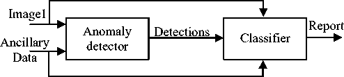
Fig.1 Basic Traditional ATR architecture
This architecture consists of two main components:
A front-end anomaly detector (pre-screener) and a back end classifier. The classifier completes the detection/clutter-rejection process. The classifier can also assign a target category to a detected object. The performances of the two primary ATR components can be measured separately. Alternatively, the ATR can be treated as a single black box. In this latter case, the only concerns are the inputs and outputs. The inner workings of the ATR, that is, how it transforms the inputs to the outputs.
An ATR might process each input frame of data independently from the next frame, as in synthetic aperture radar (SAR) or an infrared-step-stare system. A triggered unattended ground system can rarely generate but a single frame of data. Or, the ATR could process video data, using temporal information to help make its decisions. [1].
This paper is organized as follows: Section 2 illustrates a literature survey on the related work. Section 3 introduces and explains the proposed automatic target recognition technique based on HT and MI. Section 4 shows the experimental work and results. Finally, the paper is concluded in Section 5.
-
II. Related Wok
There are several algorithmic approaches to solve the problem of Automatic Target Recognition (ATR) which begins with target detection in images. Background Subtraction (BS) is a method commonly used for the detection of moving objects when the camera is fixed. In this method, a reference image is taken as the background and then compared to the next image, thus detecting the changes occurring at the reference background [7, 8, 9]. Optical flow subtraction is a generalized gradient model which uses the relationship between a series of twodimensional image and the speed [10]. Temporal Difference Method [11] is based on the detection of the differences of the sequential video frames. Another method is the active contour model, which is an edgebased segmentation method [12, 13]. This method is based on the framing of the edges of an object with a closed frame by the energy function within the object area [14]. Methods such as mean shift algorithm [15] which is based on the principle of analyzing the multiform property space and of using its property set are primary image processing methods used in target recognition. Potential based methods originated from the edge potential function (EPF) model [16]. EPF based method has been applied to many real world problems, e.g., ground target detection [17, 18], ear detection [19], aperture radar scene matching [20] and video retrieval [21, 22].Also, Atomic Potential Matching (APM) model provides a remedy for the conventional EPF model [23].
Some other automatic target recognition techniques which need three-dimensional (3D) modeling of the targets by using a set of two-dimensional (2D) views of the object to detect and recognize targets in difficult domains in order to accurately model small, irregularly shaped targets is presented in [24]. Indirect target recognition method for overhead infrared image sequences is introduced in [25] to detect and recognize targets in the cases that the target is occluded or hided completely.
-
III. The Proposed Automatic Target Recognition Approach Based On Ht And Mi
The proposed recognition technique passed through five stages which are: edge detection by Sobel edge detector, thinning as a morphological operation, HT, matching process and finally measuring the MI between target and the available database images. The first four stages (edge detection, thinning, HT, Matching) are done sequentially while the fifth stage (MI measurement) can be performed in parallel with the previously mentioned four stages. The cause of using these stages is described in details as follows:
The Sobel operator is selected as an edge detection method because it has the ability to detect only strong edges [26] in the image which is more suitable to our case of study. Whereas, there is no need to detect weak edges as the canny edge detector operates. The thinning is used as a morphological operation which makes the detected edges in images as sharp and straight as possible which helps the HT in the next stage to work successfully and group the extracted edge points to an appropriate set of lines. HT as mentioned before helps in detection of straight lines in both of target image and database images. This also, helps the matching process in the next stage to work successfully with minimum processing time. Whereas, matching process is applied only on straight lines and it is not applied on all detected edges. MI is used as a similarity measure between target and database images and this process doesn’t depend on the previously mentioned four stages. So, it can be performed in parallel with the other four stages to reduce the required processing time and the computational complexity. Besides, MI makes few assumptions about how the intensity values of the images are related. It only relies on statistical dependence. Therefore, the MI can be used as a similarity measurement even if the target image suffers from some artifacts such as noise and blurring effects. Moreover, MI is used as a confirmation method to emphasize and finally realize the matching between the target image and its corresponding database image after first recognition by matching the detected straight lines using HT in both target and data base images.
A. Implementation of proposed automatic target recognition approach
The implementation of the proposed ATR approach is explained in details in the following steps:
-
(1) Apply Sobel edge detector on both target image ( im T ) and the database images ( im Dn ). Where, n is the number of the database images and T refers to the target image number. The output from this step will be an edged target image ( imT-edge ) and edged database images ( imDn- edge ).
-
(2) Apply thinning process on the edged images ( im T-edge & im Dn-edge ). This step is important to make the detected edges in images as sharp and straight as possible. Thinning is a morphological operation that is used to remove selected foreground pixels from binary images, somewhat like erosion or opening. In this step it is commonly used to tidy up the output of edge detectors by reducing all lines to single pixel thickness [27].
-
(3) Transform the output images from step 2 into HT space to group the extracted edge points to an appropriate set of lines. Whereas, each edged pixel on both images will have r and θ . According to the parametric representation of a line, the edge points that have the same r and θ are belonged to the same line. Where, r is the distance from the origin to the line along a vector perpendicular to the line and θ is the angle of the perpendicular projection from the origin to the line measured in degrees clockwise from the positive x-axis [28].
-
(4) A median deviation value (M) of a 3×3 window size around the edged pixels ( xi ) is calculated for each edged pixels on the straight lines in both target and database images. Then, there will be an array (A1) represents the median values of the line pixels in target image. Whereas, A1=[M 1 ,M 2 ,……M m ], where, m is the number of edged pixels on straight lines in array A1 and another cell array (A2) represents the median values of the line pixels in data base images. Whereas:
a 1 a
A 2 =
.
.
an
Where, n is the number of database images and an=[ M1,M2,……Ms], where, s is the number of edged pixels on straight lines in sub-array a1.The cell array (A2) consists of a number of sub-arrays. Each sub-array contains the median values of the line pixels in each of database images. In this step, two or three edged thinned lines in the target image are selected to be used for comparing and matching with their corresponding lines in database images in order to reduce the processing time of this step.
-
(5) A normalized cross-correlation (NCC) formula is used to find the best match between median values in the array (A1) which represents the line pixels in target image and the cell array (A2) which represents the median values of the line pixels in database images.
NCC is used to find the best match between a small size template and larger array. Here, A1 is considered as a template image and the larger array size will be A2.
Where, NCC formula [29].
NCC ( A1, A 2) =
is
calculated according to the following
E [ f ( x , У ) - J ][ t ( x — u , У - v ) — t )]
x , y
u , v
{E Jf (x,У) - f ] E, Jt(x - u,У - v) -1] }05 x,y x,y u,v (1)
-
(6) The Maximum of NCC gives the indication about the best correlation between the values in array A1 and the sub-array (a n ) in A2. Then, Max ( NCC ) refers to a certain a n , then n refers to the index number of the database image which matched with the target image. So, the target image is initially recognized with its corresponding database image.
-
(7) The mutual information (MI) between both of target and database images is consequently computed to emphasize and finally realize the recognition between target image and its corresponding database image. MI is calculated according to the following equation [30]:
LL
MI ( Im T, Zmc ) = £ £ h„T ^ (I, 1 2 )log 2
- 1 = 1 - 2 = 1
himT , imD ( i 1, i 2)
himT ( i 1) himD ( i 2)
MI is used to evaluate the correlative performances of the target image and the database image. Where, L is the number of histogram bins ( L =256 in case of gray scale images), himT,imD indicates the normalized joint gray level histogram of images im T and im D . Also, h imT (i 1 ), h imD (i 2 ) indicate the normalized marginal histograms of the two target image and database images respectively. After that, the MI values between the target image and the all database images are recorded.
-
(8) If the highest MI value is the value of MI between the database image and the target image which is recognized in step (6) then target recognition is realized.
-
(9) Go to step (6) again and change the threshold value if the highest MI value is not the value of MI between the database image and the target image which is determined in step (6).
Fig.2 illustrates the proposed ATR approach. Moreover, for simplicity and more clarification, the algorithm of the proposed ATR approach is shown as the following: Input : im T , im Dn
-
1- Sobel ( im T , im Dn )
Output: ( im T-edge , im Dn-edge )
-
2- Thinning ( im T-edge , im Dn-edge )
Output : thin edged lines
-
3- Hough Transform ( im T-edge , im Dn-edge )
Output : thin edged straight lines
-
4- Matching:
a- Median value M b- A2={a1,a2,….an} c- Get Max (NCC) then
(Target initially recognized with its n database image)
if MI (imT, ImDn) is the highest value for the same database image number n in step (c)
then
Target is finally realized and recognized with its corresponding database image (Dn)
else
Goto step (c) and change the threshold value end end
-
IV. Experimental Work and Results
A Well-known UC Merced Land Use Dataset [31] is selected as database images to prove the effectives and accuracy of the proposed ATR approach. UC Merced Land Use Dataset consists of 21 class land use image dataset (buildings, airplanes, forest,…etc.) meant for research purposes. There are 100 images for each class. Each image measures 256x256 pixels. So, the experimental work was done on about 2100 different images. The images were manually extracted from larger
images size from the USGS National Map Urban Area Imagery collection for various urban areas around the country [32]. The pixel resolution of this public domain imagery is 1 foot.
Having a set of 21 different types of images I = {im1, im2, ….im21} with size 256×256 pixels which represent the target images. Every image is selected from a set of 100 images which represents different classes of the Merced dataset which represent the database images.
The results are compared with one of the recent techniques which is based on stable edge weighted HOG The stable edge weighted HOG technique is based on the stability of each edge fragment, represented by the relative change of the skeleton over a given range of threshold of a map which was analyzed to select the steady ones. And, 2D template images are obtained by projecting a 3D model of the target which is constructed from the 3D data of the scene with the real time observation parameters, and then they are manually labeled to reserve the borderlines. After that, the edge weighted HOG features are extracted and the characteristics of the template image matching to achieve target recognition. The 2D template images are obtained by projecting a 3D model of the target which is constructed from the 3D data of the scene with the real time observation parameters, and are manually labeled to reserve the borderlines. Finally, edge weighted HOG features are extracted and the characteristics of the template image matching to achieve target recognition. [33].
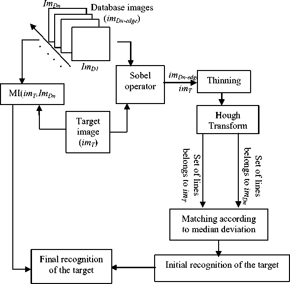
Fig.2. Proposed ATR approach based on HT and MI
Table.1 shows that the proposed ATR approach succeeded to recognize about 20 target images, While, the stable edge weighted HOG technique succeeded to recognize only 14 images. So, the proposed approach gives more accurate recognition rate than other technique which is based on stable edge weighted HOG. Furthermore, the proposed technique doesn’t need a projection of the 3D data of the scene to obtain the 2D template images. Moreover, the proposed technique is fully automated to recognize the target without need to manually labeling the 2D template images as in the stable edge weighted HOG technique.
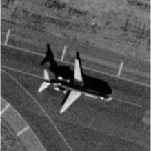
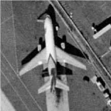
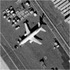
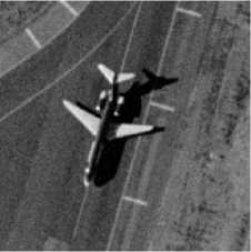
Fig.3 (a), Fig.3 (b) and Fig.3 (c) show some of database images which represent some types of airplanes selected from 100 airplane images as an example selected from one class of Merced dataset images and Fig.3 (d) show one of the target images.
Table 1. Comparison between the proposed recognition technique and the stable edge weighted HOG technique
|
Comparison item |
Proposed ATR approach |
Stable edge weighted HOG technique |
|
No. of Succeed recognition |
20 |
14 |
|
No. of False recognition |
1 |
7 |
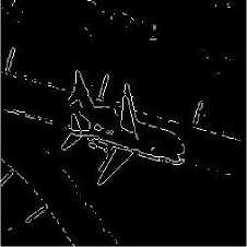
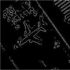
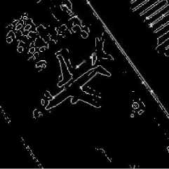
The whole procedures of the proposed target recognition technique are explained in details in figures by applying the pre-mentioned steps in the previous section on images shown in Fig.3 as an example of our work. Fig.4 (a), Fig.4 (b) and Fig.4 (c) show the edged database images im D1-edge , im D2-edge and im D3-edge respectively, and Fig.4 (d) shows the edged target image im 1-edge after applying the Sobel edge detector.
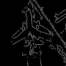
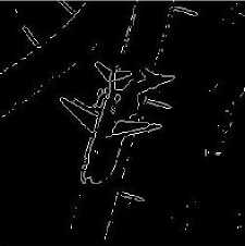
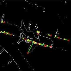
Fig.5 (a), Fig.5 (b) and Fig.5 (c) show the edged database images im D1-edge , im D2-edge and im D3-edge respectively, and Fig.5 (d) shows the im 1-edge which represents the target image after applying the Sobel edge detector + thinning + Hough transform (HT). As shown in Fig.5, it is notice that the straight lines in both of database images and target image are detected and assigned by colored lines due to the HT effect. These straight lines are considered as the extracted features which are used for matching between database and target images. By applying the steps from 4 to 6 in the proposed target recognition approach as in the pre-described section, the target image ( im 1 ) is initially realized and recognized with its corresponding database image ( im D1 ). The MI between the target images ( im 1 ) and the 100 airplanes database images ( im D1 , im D2 ,…… im D100 ) is measured to verify and emphasize the recognition between the target image ( im1 ) and its corresponding database image ( im D1 ). As shown in graph which is illustrated in Fig.6. The highest value of MI (1.32) is verified between the target image ( im1 ) and the database image ( im D1 ). Whereas, the other values that belong to the MI between im 1 and the remaining database images are lower than MI ( im 1 , im D1 ). So, MI ( im 1 , im D1 ) > MI ( im 1 , im Dn ) where n≠1.
One of advantage of the proposed ATR approach is: it has the ability to achieve recognition between the target image and its corresponding database image even the target and the database images are not registered (are not acquired from the same point of view). This can be shown in Fig.3 (a) and Fig.3 (d) which represent the target image and its matched database image respectively. It is clear that the two images are not registered. The acquired target image is rotated and translated from the stored database image. This is because the proposed ATR approach depends on the matching between the detected straight lines in both target and database images regardless the position and the location of edges in both images.
(a)
(b)
(c)
(d)
Fig.3. (a), (b) and (c) database images im D1 , im D2 and im D3 respectively and (d) target image im 1
(b)
(a)
(c)
Fig.4. (a), (b) and (c) edged database images im D1_edge , im D2_edge and im D3_edge respectively and (d) target image im 1-edge
(d)
(a)
(c)
Fig.5. (a), (b) and (c) edged database images im D1_edge , im D2_edge and im D3_edge respectively and (d) edged target image im 1-edge after applying thinning and HT processes
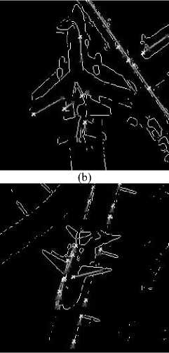
(d)
MI
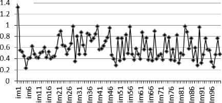
Database images
Fig.6. MI between target image ( imT ) and database images ( imDn )
-
V. Conclusion
The proposed ATR approach is not only depends on feature matching as many other methods [34][35] but also, makes a verification and emphasize the matching process by using mutual information which makes few assumptions about how the intensity values of the images are relate and it only relies on statistical dependence. Moreover, according to the results shown in the indicated graph in Fig. 6, it is proved that the target image is completely recognized with its corresponding database image. Besides, the results in Table.1proved that the proposed target recognition approach which is based on Hough transform and mutual information gives better performance and gives more recognition rate than one of the most recent techniques which is based on stable edge weighted HOG. Moreover, the proposed technique doesn’t need a 3D data modeling of the scene to obtain the 2D template images. Furthermore, it is fully automated to recognize the target. Whereas, some other techniques such as stable edge weighted HOG technique needs manually labeling the 2D template images which is sophisticated and consumes a higher processing time. Also, one of advantage of the proposed ATR approach that, it has the ability to achieve recognition between the target image and its corresponding database image even the target and the database images are not registered and not acquired from the same point of view.
References New automatic target recognition approach based on Hough transform and mutual information
- Automatic Target Recognition, B. J. Schachter, 2nd Edition, vol., TT113, ISBN: 9781510611276, March 2017.
- J.J. Yebes, L.M. Bergasa, M. García-Garrido, “Visual object recognition with 3D-aware features in KITTI urban scenes,” Sensors 15 (4): 9228–9250, 2015.
- B. Li, Y. Yao, “An edge-based optimization method for shape recognition using atomic potential function,” Eng. Appl. Artif. Intell. 35, 14–25, 2014.
- Ramesh K N, Chandrika N, Omkar S N, M B Meenavathi and Rekha V “Detection of Rows in Agricultural Crop Images Acquired by Remote Sensing from a UAV,” I.J. Image, Graphics and Signal Processing, vol. 11, pp. 25-31, 2016.
- P. K. Mishra and G.P Saroha, “studying on classification for static and moving objects in video surveillance system, I.J. Image, Graphic and Signal Processing, vol. 5, pp. 76-82, 2016.
- Tunç Alkanat, Emre Tunali and Sinan Öz, “Fully-Automatic Target Detection and Tracking for Real-Time, Airborne Imaging Applications,” International Joint Conference on Computer Vision, Imaging and Computer Graphics, pp. 240-255, VISIGRAPP 2015.
- M. Yagimli, H.S. Varol., “Real Time Color Composition Based Moving Target Recognition,” Journal of Naval Science and Engineering, Vol.5, No.2, pp.89-97, 2009.
- M.Peker, A. Zengin, “Real-Time Motion-Sensitive Image Recognition System,” Scientific Research and Essays, Vol:5, No:15, pp.2044-2050, 2010.
- S.Saravanakumar, A. Vadivel, C.G. Ahmed, “Multiple Human Object Tracking using Background Subtraction and Shadow Removal Techniques Images,” Int. Conf. on Signal and Image Processing, pp.79-84, 2010.
- S. Yamamoto, Y. Mae, Y. Shirai, J.Miura, “Real time Multiple Object Tracking Based on Optical Flows, Robotics and Automation, proceedings,” pp.2328-2333, 1995.
- C.-H. Chuang, Y.-L. Chao, Z.-P. Li, “Moving Object Segmentation and Tracking Using Active Contour and Color Classification Models,” IEEE Int. Symposium, pp.1-8, 2010
- M. Kass, A. Witkin, D. Terzoupolos, Snakes, “active contour models,” Int. Journal of Computer Vision, vol.1, No. 4, pp.321-331,1988.
- M. Maziere, F. Chassaingl, L. Garrido, P. Salembie, “Segmentation and Tracking of Video Objects for a Content-Based Video Indexing Context,” IEEE Int. Conference, pp.1191-1194, 2000.
- N. Özgen, Computer Based Target Tracking, M.Sc. Thesis, Gazi University Institute of Science and Technology, August 2008.
- L.W. Wang , J.L. Qin, “Study on Moving Object Tracking Algorithm in Video Images,” The Eighth Int. Conference on Electronic Measurement and Instruments, pp.1-4, 2007.
- M.S. Dao, F.G. De Natale, A. Massa, “Edge potential functions and genetic algorithms for shape-based image retrieval,” Proceedings of 2003 International Conference on Image Processing
- C. Li, H. Duan, “Target detection approach for UAVs via improved Pigeon-inspired Optimization and Edge Potential Function,” Aerosp. Sci. Technol. 39 (2014)352–360.
- C. Xu, H. Duan, “Artificial bee colony (ABC) optimized edge potential function (EPF) approach to target recognition for low-altitude aircraft,” Pattern Recognition, Lett. 31 (13) (2010) 1759–1772.
- F. Battisti, M. Carli, F.G.B. De Natale, A. Neri, “Ear recognition based on edge potential function,” Proc. SPIE 8295, Image Processing: Algorithms and Systems X; and Parallel Processing for Imaging Applications II, No. 829508,February, 2012, http://dx.doi.org/10.1117/12.909082.
- Y. Wang, J. Yin, “Intelligent search optimized edge potential function (EPF)approach to synthetic aperture radar (SAR) scene matching,” IEEE Congress on Evolutionary Computation (CEC), (pp. 2124–2131). IEEE, July,2014.
- M.S. Dao, F.G. DeNatale, A. Massa, “MPEG-4 video retrieval using video-objects and edge potential functions,” Advances in Multimedia Information Processing-PCM 2004, Springer, Berlin, Heidelberg, pp. 550–557, 2005.
- M.S. Dao, F.G. DeNatale, A. Massa, “Video retrieval using video object-trajectory and edge potential function,” Proceedings of 2004 International Symposium on Intelligent Multimedia, Video and Speech Processing, October,2004. ICIP 2003. Vol. 3, pp. III-729. IEEE, September, 2003.
- B. Li, H. Cao, M. Hu, C. Zhou, “Shape matching optimization via atomic potential function and artificial bee colony algorithms with various search strategies,” Proceedings of 8th International Symposium on Computational Intelligence and Design (ISCID 2015), vol. 1,pp. 1–4, December 2015.
- C. F. Olson and D. P. Huttenlocher “Automatic Target Recognition by Matching Oriented Edge Pixels,” ieee Transactions on image processing, Vol. 6, No.1, Jan 2012.
- H. Zhu, L. Deng and G. Lu, “Indirect target recognition method for overhead infrared images equences,” Elsevier, Optik, 126, pp.1909-1913, 2015.
- Y. Weiping, W. Xuezhi , B. Moran, A. Wheaton, N. Cooley, “Efficient registration of optical and infrared images via modified Sobel edging for plant canopy temperature estimation,” Elsevier, Computers and Electrical Engineering vol. 38, pp. 1213–122, 2012.
- J. R. Parker, Algorithms for Image Processing and Computer Vision, 2¬nd ed., Wiley computer publishing, 2010.
- R. M. Bahy, G. I. Salama, T. A. Mahmoud, “Registration of Multi-Focus Images Using Hough Transform,” 29th National Radio Science Conference (NRSC), Cairo, Egypt, pp. 279-284, 10-12 Apr. 2012.
- https://www.mathworks.com/help/images/ref/normxcorr2
- R. Shams, N. Barnes and R. Hartley, “Image Registration in Hough Space Using Gradient of Images,” IEEE International Conference on Acoustics, Speech and Signal Processing (ICASSP), Glenelg, Australia, Jun. 2007.
- http://vision.ucmerced.edu/datasets/landuse.html
- https://nationalmap.gov
- W. Shen, X. Ding, C. Liu, C. Fang and B. Xiong, “New Method of Ground Target Recognition Based on Stable Edge Weighted HOG,” Asia-Pacific International Symposium on Aerospace Technology, APISAT2014, Published by Elsevier Ltd., 2015.
- Akarlari, M. Yagimli, “Target Recognition with Color Components and Sobel Operator,” Int. Journal of Electronics; Mechanical and Mechatronics Engineering, vol.2, no.4, pp. 305-310, 2012.
- Bai Li, “Atomic Potential Matching: An Evolutionary Target Recognition Approach Based on Edge Features,” Elsevier, Optik 127, pp. (3162-3168), 2016.
