New type of detachable contact joints for aluminium cell busbar arrangement

Author: Galemov Takhir T., Petrov Alexandr M., Vasilyev Yury V., Granitsky Lev V., Kirko V.I., Pobyzakov Vladimir I.
Journal: Журнал Сибирского федерального университета. Серия: Техника и технологии @technologies-sfu
Article in issue: 1 т.1, 2008.
Free access
The new type of detachable contact joints (DJC) for the aluminium industry is offered. It is shown, that DJC with cylindrical split contact inserts allow to provide stability of electrotechnical characteristics of connection from -50 to + 40ºC.
Resistivity, pressure, contact, detachable joints, aluminium cell busbar
Short address: https://sciup.org/146115868
IDR: 146115868 | UDC: 537.312.9
Text of the scientific article New type of detachable contact joints for aluminium cell busbar arrangement
The highest energy losses at power supply to aluminium cells occur at riser-busbar contact joints. In real operational situation the contact joints are greatly affected by temperature drops (from –50 to + 40ºC in Siberia). Under such thermal stresses the detachable contact joints (DCJ) reveal gradual increase of resistivity due to weakening of bolt joints and corrosion of contact surfaces. Therefore, it is necessary to perform constant monitoring and adjustment of such DCJ. To improve the performances of electric contacts in riser-anode busbar arrangement the additional welding of busbar connections is used. This quite evidently results in the increase of time consumption and cost expenses at the cell startup and during the cell overhauls.
This paper presents a new type of DCJ which allows to solve the problem of stability of electrotechnical properties of contact joints of aluminium cell busbar and to eliminate the necessity to apply welding operations.
1. Peculiar features of the existing DCJ of aluminium cell busbar arrangement
It is well known, that local points of electric contact at DCJ assembling appear on distorted surfaces where non-conductive layer is destroyed under pressure and conductive micro-contact is formed. A set of such micro-contacts results in formation of macro-contact. To achieve efficient busbar connection it is advisable to provide maximal amount of contact surfaces with uniform distribution across the overall contact area. In general, the latter is obtained by means of preparation of the surface and by means of appropriate selection of methods applied for fastening of contact groups.
According to [1], one of the major factors required for provision of low resistivity at busbar connections consists of sufficient level of uniform distribution of pressure in the contact. However, in case of fastening of the busbar surfaces by means of bolt joints the contact area is concentrated mainly around the bolt hole where the highest pressure is generated. Fig. 1 presents schematically the pattern of current spot on the internal contact surface near the bolt joint. Taking into consideration that the maximal pressure is localized around the bolts, the highest deformation of the busbar material occurs in the regions where the surface distortions are smoothed resulting in formation of excellent contact area.
Pressure concentration near the bolt holes deteriorates the performances of such joints in case of ambient temperature drops. Due to the fact that the linear expansion coefficient of the aluminium busbars is higher in comparison with steel bolts, the pressure in the contact area decreases at cooling and increases at heating. Respectively, the contact resistivity is altered: it increases at temperature decrease and decreases at its increase.
Taking into account that the maximal permissible loads near the bolt joints are limited with the strength of aluminium busbars, the bolt joint fastening in actual environment should be periodically monitored and adjusted in accordance with the seasons.
Fig. 2 illustrates schematically the DCJ applied for the existing anode busbars. The connection of the detachable aluminium busbars is performed by fastening with steel bolts via regular steel washers or Belleville washers.
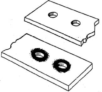
Fig. 1. Internal contact surface near the bolt joint
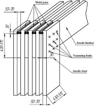
Fig. 2. Detachable contact joint used at the smelters of OAO «Russian Aluminium»
Even in combination with the Belleville washers, the bolt joint is not sufficiently stable under the altering conditions of the DJC temperature. Therefore, modified DJC are used with extra welding of connecting joints according to [2].
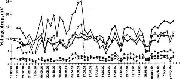
Fig. 3 presents the curves of voltage changes at the DJC with bolt joints and at the modified DJC.
The presented measurement values demonstrate that the voltage drop at Cell No. 1755 (riser 1) at amperage of 34.3 kA amounts to 15 mV (ambient temperature 8ºC). Voltage drop at Cell No. 1965 (riser 1) at amperage of 39.9 kA amounts to 31 mV (ambient temperature 4ºC), and at Cell No. 2103 (riser 1) at amperage of 39.11 kA voltage drop amounts to 24 mV (ambient temperature 15ºC).
It is evident, that the application of welding for DJC really decreases the contact resistivity more than 5-6 times and increases its stability. Significant variations of DJC contact resistivity are observed – 2-3 times depending on the season, the contact voltage drops increases up to 20 – 25 mV in summer and decreases down to ~ 5 mV in winter.
DJC voltage at anode busbar за acording to the project EYu 1378.10.00
Remarks: 1. (’ell No. 1965 - the contacts are assembled with - *— 1755, transient —»— 1755, contact contact paste; 3-riser cell busbar arrangement -♦- 1965, transient —o— 1965, contact 2. The data of 17.08.01 after DJC welding with leg joint, Cell 1965 „ e_ 2103, transient —o— 2103, contact
Fig. 3. DJC voltage as a function of time, Cells Nos. 1755, 1965, 2103
The application of welding complicates the procedures of DJC assembling and disassembling. Therefore, despite quite acceptable result in terms of decrease of contact resistivity and provision of its stability, the welding cannot be considered as optimal technological practice.
We developed another type of DJC [3], based on the utilization of split contact insert which combines the simplicity of maintenance of bolt joints and resulting in decrease of contact resistivity together with its season stability.
2. DJC on the basis of split contact inserts
Fig. 4 presents schematically the developed design of contact joint of current conducting busbars where one or several DJC bolt joints are replaced with cylindrical split contact inserts.
Fig. 5 illustrates the design of the cylindrical split contact insert.
The proposed DJC design consists of current conducting busbars, several rows of bolts with spring washers fastened with nuts. A portion of the bolts is replaced with cylindrical split contact inserts. For this purpose in the current conducting busbars cylindrical through holes are made for installing of the cylindrical split contact inserts with conical bushings. The conical bushings fastened by means of bolts with spring washers.
Fig. 6 illustrates the interrelation between the value of contact resistivity and various fastening strength [4] with contact surfaces covered with electrical compound.
Depending on processing of busbar surfaces, the specific contact resistivity can vary up to 10 times at one
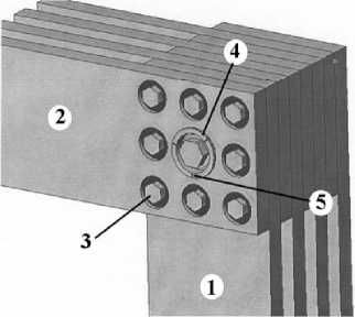
Fig. 4. Schematic view of DJC design with one cylindrical split contact inserts 1 – anode riser, 2 – anode busbar, 3 – bolt (steel), 4 – split insert, 5 –split
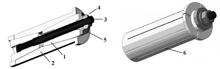
Fig. 5. 4-piece cylindrical split contact insert in complete with two steel spacers 1 – spacer, 2 – split insert, 3 – steel pin, 4 – nut, 5 – washer, 6 – split
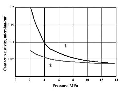
Fig. 6. Contact resistivity as a function of contact pressure determined in [4]. Curve 1 corresponds to pressure increase at fastening; 2 – to pressure decrease
and the same fastening pressure. Moreover, at the pressure higher than 8 MPa the contact resistivity varies slightly in terms of per cent.
One important consequence from the Fig. 6 is that at the load release the specific contact resistivity reveals hysteresis, and the electric resistivity increases according to the curve located lower than the load curve. This evidences that the bolt joint slackening should result in partial conservation of residual resistivity of contact unit obtained at a higher contact pressure.
The cylindrical split contact inserts are manufactured of low-resistance materials (cooper, aluminium, etc.). The fastening conical bushings can be made of both low-resistance materials (copper, brass), and structural materials (steel).
The utilization of the cylindrical split contact inserts allows to compensate for the increase of the transient resistivity because these inserts provide reverse dependence of the transient resistivity changes at temperature changes in comparison with (2).
At contact joint heating, the pressure on the interface between the cylindrical split contact insert and current conducting busbar remains higher than certain minimal limit amounting to:
р > р, v ≥ lim
F cos α -ν cv sin α
2 π dvsNs sin α+ν cvcos α
where F – bolt fastening strength of conical bushings, NS – number of busbars in the package, α – half-angle of cone opening of conical bushing, νcν – coefficient of static friction of materials conical bushings– cylindrical split contact insert. At heating the equation (1) is maintained due to inward motion of conical bushings into cylindrical split contact insert under the action of the forces generated by the bolts with spring washers. Because the values of νcν for metal surfaces is not higher than 0.1 – 0.4 (and at application of conducting lubricants this value can be decreased significantly), then from the practical point of view it is sufficiently to select the appropriate angle of conical bushings and, respectively, of internal surfaces of cylindrical split contact inserts in the range of:
sin α ~ 0 . 3 ÷ 0 . 5 ⋅ν cv , (2) to obtain the following value:
P lim ~ 0 . 7 ÷ 0 . 8 ⋅ P li m m ax . (3)
The application of sealing conducting paste at assembling of current conducting busbars with installed cylindrical split contact inserts in addition to improvement of electric contact results also in decrease of νcν and, respectively, to increase of Plimmax ..
Therefore, at temperature increase for DJC with cylindrical split contact inserts the contact resistivity decreases for the overall contact joint due to decrease of transient electrical resistivity in the region of bolt joints (1) (taking into account (2)) at maintaining of the same electrical resistivity in the region of cylindrical split contact inserts.
When temperature decreases at current conducting busbars taking with into account the condition tg α < k (which is automatically fulfilled at selection of the angles for internal surfaces of cylindrical split contact inserts and conical bushings in accordance with condition (2)), the friction force in the set “conical bushings–split contact insert” prevents reverse motion of the conical bushings under the action of the ejection forces. It results in occurrence of self-fastening effect of the cylindrical split contact inserts on conical bushings.
The cylindrical split contact insert is characterized with reverse temperature dependence of the transient resistivity variations relatively to regular bolt joints (2), because at cooling the contact pressure at the surface of cylindrical split contact insert–current conducting busbar. As a consequence, the combination of bolt joints and cylindrical split contact inserts in the contact joint of current conducting busbars allows to stabilize the oscillations of transient resistivity of the contact joint due to selection of the properties of cylindrical split contact inserts conforming the requirements of technical specifications.
Actually, the parameters of the joint of current conducting busbars should be selected in such way that to provide the current distribution across the bolt joints and cylindrical split contact inserts in proportion of about 50 / 50%,
R b ≈ R ν ~ 2 R S , where RS – required value of the resistivity of overall contact joint.
To improve of electrical contact during assembling and operation as well as reduction of coefficients of static friction we can use sealing conducting pastes and/or lubricants in cylindrical split contact inserts. For instance, coating BROS 10-1,5, lubricant EKS-200, contact lubricant TEP 300, as well as convenient graphitic lubricant can be utilized used.
The experimental results demonstrated that the application of DJC with one cylindrical split contact insert in combination with conducting paste reduces the voltage drop at the interface more than two-fold and provides stabilization of variations of contact resistivity in amount of 10-15% of maximal value in temperature range from –45 to +70ºC.
Conclusions
The performed research has demonstrated that the DJC design on the basis of cylindrical split contact inserts allows to decrease the contact resistivity in the contact units of aluminum cell busbar arrangement. The obtained theoretical and experimental results illustrate that the application of DJC with split contact bushings can lead to the following:
-
• reducing the voltage drop in about 3-7 times in comparison with the existing DJC designs;
-
• increasing current conductivity of the unit;
-
• excluding the impact of temperature variations on the contact pressure and, consequently, to eliminate their impact on electro-technical parameters;
-
• preventing depressurization of the contact interfaces between the bushing and current conducting busbars, thus reducing the effect of corrosion on electro-technical parameters of DJC and increasing its life-time.
