Noise minimized high resolution digital holographic microscopy applied to surface topography

Author: Achimova Elena, Abaskin Vladimir, Claus Daniel, Pedrini Giancarlo, Shevkunov Igor, Katkovnik Vladimir
Journal: Компьютерная оптика @computer-optics
Section: Дифракционная оптика, оптические технологии
Article in issue: 2 т.42, 2018.
Free access
The topography of surface relief gratings was studied by digital holographic microscopy. The applicability of the method for quantitative measurements of surface microstructure at nanoscale was demonstrated. The method for wavefront reconstruction of surface relief from a digital hologram recorded in off-axis configuration was also applied. The main feature is noise filtration due to the presence of noise in the recorded intensity distribution and the use of all orders of the hologram. Reconstruction results proved a better effectiveness of our approach for topography studying of relief grating patterned on a ChG As2S3 - Se nanomultilayers in comparison with standard Fourier Transform and Atom Force Microscope methods.
Digital holography, digital image processing, diffraction gratings
Short address: https://sciup.org/140228726
IDR: 140228726 | DOI: 10.18287/2412-6179-2018-42-2-267-272
Text of the scientific article Noise minimized high resolution digital holographic microscopy applied to surface topography
Diffractive optical elements (DOE) are indispensable in a variety of optical applications, including measurement instruments and imaging devices. Advanced nanotechnologies and nanophysics use chalcogenide glasses (ChG) as basic components in the engineering of DOE [1]. Optical properties of ChG films, such as absorption coefficient and refractive index, can be changed by light or e-beam exposure. The direct formation of micro and nano-relief on the ChG surface under the polarized coherent radiation is a phenomenon, both of applied and scientific importance [2, 3]. From the application point of view, the phenomenon is useful for the production of a variety of high-performance DOE without any additional/wet development and its scientific significance lies in discovering a new feature interaction of light and the ChG.
The topography of surface relief gratings (SRG) is the main feature determining the success of SRG application. The optical quality of the relief surface is very important for designing DOE by recording, printing or master hologram realizing. However, sometimes it is possible to perform direct thermal printing on polymer film from DOE of a large number of copies without master [4]. Finding the methods appropriate for the study of each unit of DOE topography is a priority task.
Due to the high resolution required, the profile and surface of SRG are conventionally measured via Atom Force Microscopy (AFM) or Scanning Electron Microscopy (SEM) [5, 6]. Each of the above methods has advantages and disadvantages. AFM is a precision technology giving detailed images of the sample’s surface, but it is to be pointed out that the field of view in AFM is restricted, which allows one to view only a limited part of the surface. In addition, due to the nature of AFM tip, the topography of sinusoid-like surface structure cannot be measured exactly, which leads to the appearance of the artefacts distorting the surface presentation. To create a SEM image, the incident electron beam is scanned line by line in a raster pattern across the sample surface. The SEM method requires an electrode deposited on the surface that would irreversibly change the transmission or damage the surface profile of the lithographically manufactured DOE. In case of e-beam sensitive medium, the electron irradiation can greatly influence the DOE recording. AFM and SEM are time consuming scanning methods, requiring expensive equipment and complicated software.
Digital holographic microscopy (DHM) is a noncontact full-field technique, which can partially eliminate the negative effects of other methods. DHM is a powerful interference technique having several features that make it an interesting alternative to conventional microscopy. It is worth mentioning that conventional microscopy can easily generate two dimensional images of a sample surface but cannot measure the vertical dimension (profile) of the sample. The main characteristic of DHM is the capability to retrieve amplitude and phase information of a wavefront reflected/transmitted by a microscopic object. DHM can be used for the measurement of 3D microstructure, moreover it has also been applied in many fields including topography examination, morphological monitoring of biology objects, particle studying, etc. [7]. The phase information allows one to make the surface topography measurements with nano-meter vertical resolution [8]. Deformations can be measured by evaluating the changes between the phases recorded at two states of the sample [9]. Based on the double exposure principle, phase aberrations, which may emerge in a single off-axis holographic reconstruction, can be compensated, as discussed in [10].
Theory and experimental setup
In this paper we use DHM together with the noise suppression iterative sparse technique for the 3D high accuracy reconstruction of SRG pattern on a ChG As 2 S 3 – Se nanomultilayers (NML). We are concentrated on the image-plane holography because it better demonstrates the advantages of the sparse modelling of the wavefront than the other holographic methods.
ChG As2S3 –Se NML was produced by a computer controlled cyclic thermal vacuum deposition through the mask [11]. The technology enables film deposition control within the whole sample thicknesses in the range from 0.005 µm to 3.0 µm. Thermal depositions occur at rather low temperatures (400-600°C). Rotating the sample over a heater of the condensed zones decreases the local sample temperature and prevents interlayer diffusion in NML. Otherwise the deposited nanolayers turn into monolayer. The NML sample contains alternating As 2 S 3 nanolayers with the thickness of 15 nm and Se nanolayers with the thickness of 10 nm. The total number of the nanolayers was 200, the thickness modulation period of the pair As 2 S 3 –Se layers was about 25 nm. The last-mentioned parameter is critical in the recording process for obtaining high quality surface relief.
When a laser beam with photon energy equal or above the band gap energy irradiates the ChG thin film, a strong interaction of the light with the material takes place. Due to the photosensitivity of the ChG different photo/thermo-induced structural transformations occur under laser irradiation. The induced structural transformations depend on: the material properties, wavelength, intensity, and polarization of the laser beam. At relatively low intensity levels (hundreds of mW per cm2) predominantly photoinduced phenomena, such as photopolymerization, photo-viscosity, etc. take place [2]. An interferometric procedure for producing a step grating relief the SRG on the As 2 S 3 –Se NML has been described [12], where a CW laser with wavelength λ =532 nm and average spot power density on the sample from 150 to 350 mW/cm2 have been used for recording. The holographic surface gratings with a period of Λ = 1µm were recorded by two cross-polarized (±45°) laser beams with respect to the fringe of the grating. AFM measurements of the sample surface after recording show that the depth of grooves is about 120 nm.
An off-axis DHM bright-field configuration in transmission mode has been employed for the measurement of the SRG topography. The approach to recover the complex amplitude distribution transmitted by the sample includes: a method to filter the twin image and the zero diffraction order, a numerical reference calculation, and a numerical reconstruction of sample’s image [13].
The DHM setup is shown in Fig. 1. In order to obtain an environmentally robust and compact setup the laser beam was coupled in a monomode Y-coupler. The spot diameter on the sample was adjusted by the fiber/sample distance. An oil immersion objective with magnification 100× and NA= 1.25 has been used. The oil was introduced between the cover slip (0.13 mm thickness) and the first objective lens. The first diffraction order of the SRG (39°) was accepted by the aperture angle (55°) of the objective. The CCD sensor was located at the distance of 195 mm from the objective for minimum aberrations in the image. The light source had a wavelength λ =633 nm and thus the resolution of DHM was about 506 nm (the smallest resolvable object detail). The camera resolution was 2592×1944 pixel with pixel size 2.2×2.2 µm. The period of the SRG was Λ = 1µm, it was twice as large as the resolution limit.
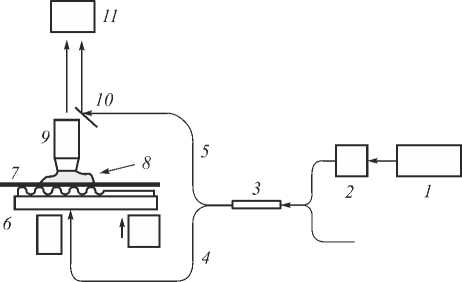
Fig. 1. Setup of the DHM: 1– He-Ne laser (λ = 0,633 µm, power = 10 mW), 2 – single-mode fiber launch device, 3 – 2×2 polarization-maintaining single-mode fiber optic coupler, 4, 5 –object and reference beams, 6 – sample with surface diffraction grating, 7 – coverslip (n = 1,51), 8 – immersion liquid (n = 1,51), 9 – immersion microscope objective, 10 – mirror and 11 – CCD-camera. I, II show two positions of object illuminations beams, namely, I – throughout the grating on NML and II – throughout the NML
The topography of the SRG was determined by comparing the phases obtained from the reconstructions of a reference object and the sample [13]. In our experiment, the holograms recorded from parts of the NML sample not exposed and with surface grating, were used as reference and the object holograms, respectively. The phases of the two reconstructions were subtracted to obtain the phase map Δφ ( x , y ) which by knowing the wavelength λ and the refraction index n can be converted into the topography:
T ( x , y ^f2^z. (1)
2n ( n — 1 )
The considered optical setup is clear from Fig. 1. Here the microscope objective (9) projects the object on the CCD-plane (11). In this way we arrive to the so-called image-plane holography, where the object image is reconstructed at the sensor plane.
The light emitted by a laser is split into two beams by a beam splitter: one beam is directed towards the surface of an object under study; the other beam is directed towards a mirror which introduces a controllable phase shift. The intensity of the sum of these two beams (hologram) is then measured by a sensor array. The complexvalued wavefront at the sensor plane is given by us = B0 exp ( jФо ) + A exp ( jФr ) , (2)
where uo = B0exp( jφ0) and ur = Ar exp( jφr) are the object and reference wavefronts, respectively. For the off-axis scenario and the spherical reference wavefront the refer- ence phase φr is defined in the form
Ф r = 2п ^ ( sjx0 + у 2 + R 2 +
+^( y - y о ) +( x - x о ) - R2 ,
where x 0 and y 0 are variables dependent on angles of the reference beam with respect to the optical axis z , ( x ; y ) are coordinates in the sensor plane, R is a curvature radius of the spherical wave, and λ is the wavelength.
The beam intensity of this beam (hologram) is defined as
I = B 0 exp ( j Ф о ) + A r exp ( j Ф r )|2 = = B о2 + A 2 + 2 B о A r cos ( Ф о - Ф r ) .
It is assumed in the image processing that the measurements are noisy and given as
Y = I + oe,
where σ is the standard deviation of the noise and ε is the standard i.i.d. zero-mean Gaussian noise, ε ~ N (0; 1). Gaussian noise sources in digital holography arise during hologram acquisition process mainly due to camera noises.
Two methods have been used for data processing and the profile reconstruction. The first conventional one is based on the Fourier Transform (FT) [14]. In this method the first order items of FT corresponding to Bo Ar exp( j (φ o – φ r )) is extracted. After the inverse FT of this item the phase (φ o – φ r ) is calculated and the object phase φ o is reconstructed provided known the reference phase φ r . This estimate of φ o is FT filtered, and in this way one arrives to the final estimate. Thus, FT filtering reconstructs the object phase φ o and additionally suppresses the noise.
As alternative technique we use the variational approach originated from [15]. Following [15] we introduce auxiliary variables: U = | B 0 |2+ | Ar |2 and Z = u 0 Ar . The key point of this replacement is that the intensity I , originally quadratic with respect to the amplitudes B o and A r becomes linear function on the new variables U and Z . Then I can be rewritten as
I = U + ( V * + Z * V ) , (6) where V = exp( j φ r ) and then u 0 = Z / A r .The idea of this approach is to optimize the lost function minimizing the deviation of the estimate from the measurements. The technique is based on the assumption that the variables Bo , φ o , Ar are invariant in a small neighborhood Xm of each m- th pixel of the observations and the criterion is of the least square form
J m = S w ( q ) [ Y ( q )- I ] • (7) q e X m
Where w ( q ), Σ qЄXm w ( q ) = 1, is a weight function applied to the variables in the neighborhood of X m .
Contrary to the FT method the above variational approach allows one to use full power of the hologram (in Fourier domain it means the use of all orders of the hologram). That is the principal advantage of the variational approach potentially guaranteeing a better accuracy and a better resolution of imaging. The criterion (7) is highly nonlinear with respect to unknown quantities Bo, φo, Ar, but with introduced auxiliary variables V and Z, the variational problem becomes much simpler [16].
Further development of that technique was produced in the recent paper [18]. The key idea of the new algorithm is the application of the sparse approximation technique [17] for modelling the object amplitude and phase as functions of the coordinates. The sparsity hypothesis assumes the existence of such functions. Moreover, both the phase and amplitude can be approximated by a series of a small number of those functions. This compact approximation enables good noise suppression and the robustness of the estimates with resecting various disturbances.
The details of this iterative algorithm referred as Sparse Phase and Amplitude Reconstruction (SPAR) can be seen in [18]. In this paper a number of modifications have been made in the algorithm in according with features of experiment and sample under investigation. First, a spherical reference wavefront as well as a plane one are incorporated in (7) contrary to the linear wavefront which is only exploited in [18]. Second, the operating window dimensions xm are 20-by-20 pixels, and Gaussian standard deviation is 5, which have been produced to improve the reconstruction results. The windows define the square for the reconstruction around the pixel of interest. Window 20-by-20 means the using 20×20 =400 equations in a minimization problem for each pixel.
Results
To discuss our approach let us start with the result obtained by FT technique.
The conventional DHM imaging technique uses a FT algorithm followed by a filtering and an inverse FT. Topography map and a profile along one line perpendicular to the grating are shown in Fig. 2. A small part of all surface of grating (12×12 µm2) is chosen for a quick estimation of calculation algorithm. The total field of view is 40×40 µm2. The profile along a line shows the maximal amplitude of about 120 nm. Due to the high noise the grating period (which is supposed to be Λ = 1 µm) cannot be precisely determined. Nevertheless, the SRG data coincide with the optical measurements of SRG recorded on the As2S3 – Se NML [12]. Note that DHM approach is the full field express method which can be used without additional sample preparation.
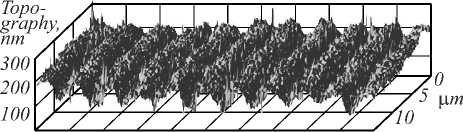
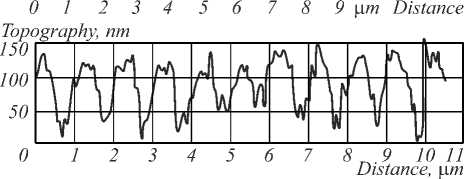
Fig. 2. Topography map (top) and cross-section (bottom) of grating at image plane obtained by FT technique
However, it is impossible to see the sinusoidal surface relief definitely. The calculated profile of lines is shown the maximal sweep of amplitudes being about 130 nm. The period of grating is not seen clearly because of the high level of noises. In comparison with the calculated period of grating (Λ = 1 µm) during holographic recording the period of grating is corrupted by noises and is not clearly seen. Thus, the obtained information about the surface relief is not sufficient.
Fig. 3 shows the SPAR reconstructions of SRG. The SPAR reconstructions clearly demonstrate the denoised images in comparison with quite noisy reconstructions obtained by standard FT shown in Fig. 2. The cross sections show in Fig. 3 (bottom) that the SPAR algorithm eliminates the noise and preserves important profile details.
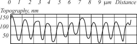
О 1 2 3 4 5 б 7 8 9 10 11
Distance, цт
Fig. 3.Topography map (top) and cross-section (bottom) of grating at image plane obtained by SPAR technique
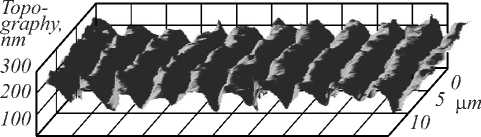
Compare the results obtained by DHM using the SPAR algorithm with the ones of the AFM technique presented in Fig. 4.
The cross-section of the DHM data (Fig. 3) matches with the cross-section of the AFM data (Fig. 4). The differences are visible in the topography maps. The noisier 3D-map in the SPAR reconstruction may result from the data presentation in different spaces in these methods. The SPAR reconstructs the phase map whilst the AFM measures the surface directly. Moreover, unlike the AFM technique in our DHM configuration the object beam passes through the glass substrate volume and residual thickness of the NML (2.5 µm), thereby embedding uncontrolled noises/phases in the topography map of SRG.
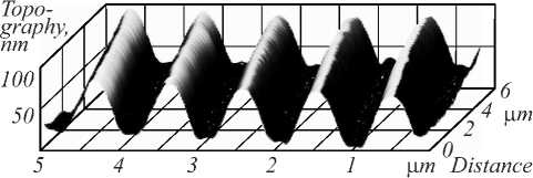
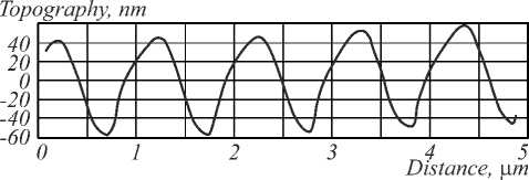
Fig. 4. Topography map (top) and cross-section (bottom) of grating at image plane obtained by AFM technique
Conclusion
To sum up, the followings results are presented in this paper.
Surface relief gratings on As2S3 –Se NML patterned by one-step direct holographic recording have been measured by DHM.
The applicability of the DHM method for quantitative measurements of surface microstructure at nanoscale has been demonstrated. In order to obtain a more effective and practical solution, two holograms corresponding to two locations on the sample’s surface have been compared to extract the relief of grating.
The SPAR algorithm for wavefront reconstruction from a digital hologram recorded in off-axis configuration of DHM has been applied with modifications developing for NML studying. The reconstruction results demonstrated a better effectiveness of our approach in comparison with standard FT.
We may conclude that the high resolution off-axis configuration of the DHM setup is applicable for SRG nanoscale investigation. The novel variational algorithm developed for the digital off-axis holography is able to produce a high-quality imaging for quite noisy data. Moreover, the surface depth and relief of grating are guaranteed in processing.
Comparing the data of surface relief recovered by DHM with those recovered by AFM one can clearly see that the SPAR reconstruction gives the results qualitatively and quantitatively coinciding with the AFM data. The proposed off-axis configuration of DHM with the developed SPAR algorithm for hologram processing may be an effective express method. Moreover, it is a good complement to the AFM and the SEM.
Our results demonstrate that the application of the DHM and the developed SPAR algorithm for image processing obviously reveal the topography of diffraction grating on As2S3 –Se NML in the presence of experimental noises on digital images.
The potential impact of the paper consists in the development of the advanced optical techniques for diffractive structures investigations at nanoscale. The proposed approach has been tested on measuring SRG of As2S3 –Se NML patterned by direct, one-step holographic recording.
References Noise minimized high resolution digital holographic microscopy applied to surface topography
- Tanaka, K. Amorphous chalcogenide semiconductors and related materials/K. Tanaka, K. Shimakawa. -New York: Springer, 2011. -242 p. -ISBN: 978-1-4419-9509-4.
- Voynarovych, I. Surface corrugating direct laser writing of microstructures in ternary chalcogenide films using a continuous-wave super-bandgap laser/I. Voynarovych, S. Schroeter, R. Poehlmann, M. Vlcek//Journal of Physics D: Applied Physics. -2015. -Vol. 48, Issue 26. -265106. - DOI: 10.1088/0022-3727/48/26/265106
- Gerbreders, A. Photoinduced mass transport in low molecular organic glasses and its practical application in holography/A. Gerbreders, A. Bulanovs, J. Mikelsone, K. Traskovskis, E. Potanina, A. Vembris, J. Teteris//Journal of Non-Crystalline Solids. -2015. -Vol. 421. -P. 48-53. - DOI: 10.1016/j.jnoncrysol.2015.04.040
- Sakai, T. Hologram copy using amorphous films as a master/T. Sakai//Optics Communications. -1978. -Vol. 24. -P. 47-50. - DOI: 10.1016/0030-4018(78)90264-X
- Bohdan, R. Methods comparing peculiarities of surface-relief recording in amorphous chalcogenides/R. Bohdan, S. Molnar, S. Kokenyesi//Physica Status Solidi A. -2015. -Vol. 212, Issue 10. -P. 2186-2190. - DOI: 10.1002/pssa.201532288
- Molnara, S. Amorphous chalcogenide layers and nanocomposites for direct surface patterning/S. Molnara, R. Bohdana, I. Csarnovicsa, I. Burunkovab, S. Kokenyesi//Proceedings of SPIE. -2015. -Vol. 9359. -935908. - DOI: 10.1117/12.2076470
- Kreis, T. Handbook of holographic interferometry: Optical and digital methods/T. Kreis. -Veinheim: Wiley-VCH Verlag GmbH & Co. KgaA, 2005. -554 p. -ISBN: 978-3-527-40546-6.
- Cuche, E. Digital holography for quantitative phase-contrast imaging/E. Cuche, F. Bevilacqua, C. Depeursinge//Optics Letters. -1999. -Vol. 24, Issue 5. -P. 291-293. - DOI: 10.1364/OL.24.000291
- Schnars, U. Direct phase determination in hologram interferometry with use of digitally recorded holograms/U. Schnars//Journal of the Optical Society of America A. -1994. -Vol. 11, Issue 7. -P. 2011-2015. - DOI: 10.1364/JOSAA.11.002011
- Claus, D. Analysis and interpretation of the Seidel aberration coefficients in digital holography/D. Claus, J. Watson, J. Rodenburg//Applied Optics. -2011. -Vol. 50, Issue 34. -P. H220-H229. - DOI: 10.1364/AO.50.00H220
- Stronski, A. Surface relief formation in Ge5As37S58-Se nanomultilayers/A. Stronski, E. Achimova, A. Paiuk, V. Abashkin, A. Meshalkin, A. Prisacar, G. Triduh, O. Lytvyn//Journal of Non-Crystalline Solids. -2015. -Vol. 409. -P. 43-48. - DOI: 10.1016/j.jnoncrysol.2014.11.010
- Achimova, E. Direct surface relief formation on As2S3-Se nanomultilayers in dependence on polarization states of recording beams/E. Achimova, A. Stronski, V. Abaskin, A. Meshalkin, A. Paiuk, A. Prisacar, P. Oleksenko, G. Triduh//Optical Materials. -2015. -Vol. 47. -P. 566-572. - DOI: 10.1016/j.optmat.2015.06.044
- Osten, W. Recent advances in digital holography/W. Osten, A. Faridian, P. Gao, K. Körner, D. Naik, G. Pedrini, A.K. Singh, M. Takeda, M. Wilke//Applied Optics. -2014. -Vol. 53, Issue 27. -P. G44-G63. - DOI: 10.1364/AO.53.000G44
- Osten, W. Comparative digital holography/W. Osten, T. Baumbach, W. Jüptner//Optics Letters. -2002. -Vol. 27, Issue 20. -P. 1764-1766. - DOI: 10.1364/OL.27.001764
- Kujawinska, M. High accuracy Fourier transform fringe pattern analysis/M. Kujawinska, J. Wojciak//Optics and Lasers in Engineering. -1991. -Vol. 14, Issue 4. -P. 325-339.
- Liebling, M. Complex-wave retrieval from a single off-axis hologram/M. Liebling, T. Blu, M. Unser//Journal of the Optical Society of America A. -2004. -Vol. 21, Issue 3. -P. 367-377. - DOI: 10.1364/JOSAA.21.000367
- Dabov, K. Image denoising by sparse 3-D transform-domain collaborative filtering/K. Dabov, A. Foi, V. Katkovnik, K. Egiazarian//IEEE Transactions on Image Processing. -2007. -Vol. 16, Issue 8. -P. 2080-2095. - DOI: 10.1109/TIP.2007.901238
- Katkovnik, V. Wavefront reconstruction in digital off-axis holography via sparse coding of amplitude and absolute phase/V. Katkovnik, I.A. Shevkunov, N.V. Petrov, K. Egiazarian//Optics Letters. -2015. -Vol. 40, Issue 10. -P. 2417-2420. - DOI: 10.1364/OL.40.002417
- Katkovnik, V. High-accuracy wave field reconstruction: decoupled inverse imaging with sparse modeling of phase and amplitude/V. Katkovnik, J. Astola//Journal of the Optical Society of America A. -2012. -Vol. 29, Issue 1. -P. 44-54. - DOI: 10.1364/JOSAA.29.000044
