Numerical simulation of the effect of air velocity on fin heat dissipation

Author: Liu H.
Journal: Бюллетень науки и практики @bulletennauki
Section: Технические науки
Article in issue: 6 т.10, 2024.
Free access
Fin has a good effect in strengthening heat dissipation, and the structure is simple, and it has been widely used in civil and industrial applications, such as radiators, automobile engine heat dissipation, air conditioning internal and external units, computer radiators and air preheaters of power station boilers. Based on the CFD numerical simulation method, the temperature change of the fin under different flow velocities is simulated. Result surface: When the calculation time is 100 seconds, when the air velocity is 0.5 m/s and 1 m/s, the heat dissipation of the fin is about 3.1℃ and 4.6℃ increasing than that at 0 m/s.
Fin, numerical simulation, air velocity, temperature change
Short address: https://sciup.org/14130179
IDR: 14130179 | UDC: 621.436 | DOI: 10.33619/2414-2948/103/41
Численное моделирование влияния скорости воздушного потока на теплоотдачу ребер
Пластины имеют хороший эффект по укреплению рассеивания тепла, и структура простая, и они получили широкое применение в гражданских и промышленных установках, таких как радиаторы, системы охлаждения автомобильных двигателей, внутренние и внешние блоки кондиционеров, радиаторы компьютеров и воздухоподогреватели котлов электростанций. На основе метода численного моделирования с использованием методов компьютерной гидродинамики (CFD) была смоделирована температура изменения пластины при различных скоростях потока. Результат поверхности: при времени расчета 100 секунд, когда скорость воздуха составляет 0.5 м/с и 1 м/с, рассеивание тепла пластин возрастает на 3.1°C и 4.6°C соответственно по сравнению с 0 м/с.
Text of the scientific article Numerical simulation of the effect of air velocity on fin heat dissipation
Бюллетень науки и практики / Bulletin of Science and Practice
UDC 621.436
At present, the research on the heat transfer performance of fin reinforced heat transfer unit mainly focuses on geometric parameters such as fin shape, fin size (height, thickness), number of fin and fin spacing [1-3]. For the casing type heat storage unit, the fined form mainly includes longitudinal fin, ring fin and spiral fin [4-6]. Hosseini et al [7] added eight longitudinal fin to the shell and tube phase change energy storage unit to study the effects of fin height and Stephen number on the performance of the phase change energy storage unit. The experimental results show that the increase of fin height can reduce the melting time, and the heat storage of the phase change unit is a function related to the fin height in the initial stage of melting. Wang et al. [8] studied the effects of fin height, fin ratio, adjacent fin angle and thermal conductivity of outer tube on the heat storage process of the unit. The simulation results show that when the fin height is half, it is conducive to strengthening heat transfer, and the influence of rib ratio on the heat storage process is not obvious. Liu et al. [9] conducted experimental research on the fin arrangement angle inside the heat accumulator, and found that when the thermal fluid temperature is lower than 50T, the melting time of the oblique fin is less than that of the vertical (horizontal) fin, but when the hot fluid temperature is higher than 60oC, the fin arrangement angle does not have much difference in the strengthening effect of heat exchange.
Theoretical basis
According to the three basic methods of heat transfer—heat conduction, convective heat transfer, radiation heat dissipation, the main factors affecting the heat dissipation efficiency are analyzed and determined. Heat conduction, heat transfer from the heat-generating device to the heat sink, and heat transfer within the heat sink are all heat conduction. Heat transfer in classical heat transfer can be described by Fourier's law of heat conductivity:
dQ=-kAdL (1)
dt dx
In the formula: dQ - thermal conductivity; T - temperature; A - heat transfer area; к -thermal conductivity; x - the coordinates on the thermal conductive surface.
It can be seen from the formula that thermal conductivity and heat transfer area are two key factors affecting heat transfer efficiency in heat conduction. Convective heat transfer can be described by Newton's law of cooling:
q = hA(Tw-Tf) (2)
In the formula: q - heat transfer; h - convective heat transfer coefficient; A - heat exchange surface area; Tw - solid surface temperature; T f - fluid temperature.
By increasing the convective heat transfer area, the heat transfer efficiency can be effectively improved. However, increasing the heat exchange area usually means that the size of the radiator is larger, which in turn leads to a larger overall size of the product, and in addition, increasing the radiator also means an increase in cost [10].
Radiant heat dissipation is mainly to choose the appropriate surface treatment method for the radiator, according to the current industry experience, this treatment method does not improve the heat dissipation efficiency of the radiator. Therefore, this article analyzes the air flow rate of the air inlet to determine the impact on the heat dissipation efficiency of the radiator.
Model building and boundary condition settings
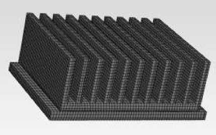
Model the fin based on ICEM and divide the mesh. The dimensions of the fin structure are shown in Figure 1 and Table 1 below, and the unstructured mesh divided is shown in Figure 2. The length, width and height of the computational domain are 0.1 m. The fin are 0.056 and 0.035 m long and wide, respectively, and 0.012 m high.
Set the top surface as the pressure outlet in Fluent, and the pressure value remains the default. The remaining five surfaces are set as speed inlets, and the speeds are 0m/s, 0.5 m/s, and 1m/s respectively. The standard k-ε model is used to calculate the model, velocity and pressure coupling uses the SIMPLE algorithm, all projects are solved using the second order upwind method. The calculation method is transient, the total step size is 1000 steps, and the time is 100s.The heat sink heating power is 2500000 w/m3, The power of this model is 14.7 w. Both airflow and heat sink temperatures are set to 20 C .
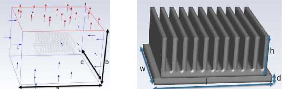
Figure 1. Fin geometry
Table1
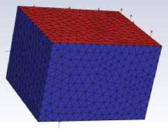
Figure 2. Fin meshing
FIN GEOMETRIC LENGTH
|
name |
Length(m) |
name |
Length(m) |
|
a |
0.1 |
h |
0.018 |
|
b |
0.1 |
l |
0.056 |
|
c |
0.1 |
w |
0.035 |
|
d |
0.003 |
Analysis of calculation results
Figure 3 shows the overall and cross-sectional temperature distribution of the fin at a velocity of 0 m/s. It can be seen that the maximum temperature of the fin is 55.2°C, the position of the highest temperature is at the bottom, and the temperature decreases with the increase in the direction of the length of the fin. At a velocity of 0 m/s, it is a natural convection situation, so the temperature gradient of the fin cross-section is not obvious.
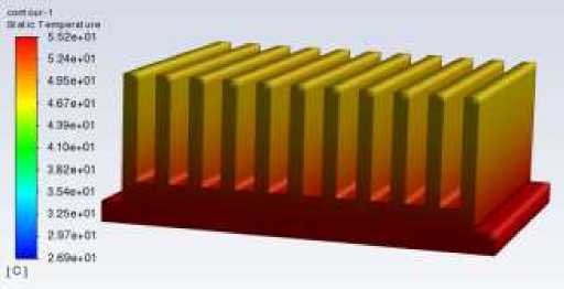
Figure 3. Temperature distribution at 0 m/s
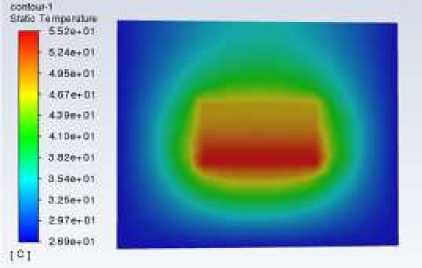
Figure 4 shows the overall and cross-sectional temperature distribution of the fin at a velocity of 0.5m/s. The calculation results show that when the velocity is 0.5m/s, the maximum temperature of the fin decreases by 3.1°C from 55.2°C to 52.1°C.
And at the cross-section of the fin, the temperature around the fin is significantly lower than 0 m/s due to the influence of the inlet airflow, and the temperature gradient in the direction of the fin height becomes significantly larger.
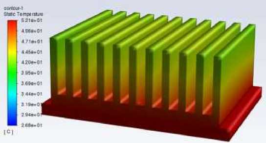
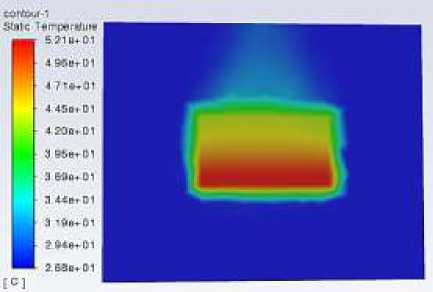
Figure 4. Temperature distribution at 0.5 m/s
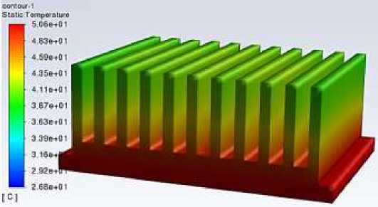
Figure 6 below shows the comparison of cross-sectional temperature distribution of the fin at velocities of 0 m/s, 0.5 m/s, and 1m/s under the same temperature scale. It can be seen from the figure that when the air velocity is 0m/s, that is natural convection, the distribution of the temperature cloud is relatively uniform. When the airflow velocities are 0.5 m/s and 1m/s, a significant velocity gradient appears in the temperature cloud.
And with the increase of airflow velocity, the maximum temperature of the heat sink also decreases, indicating that the air velocity has a greater impact on the heat dissipation of the heat sink.
Figure 5 shows the overall and cross-sectional temperature distribution of the fin at a velocity of 1m/s. The calculation results show that when the velocity is 1m/s, the maximum temperature of the fin decreases by 4.6°C from 55.2°C to 50.6°C.
As the airflow velocity increases, the temperature gradient of the fin cross-section becomes larger.
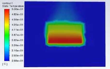
Figure 5. Temperature distribution at 1 m/s
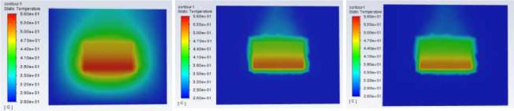
Figure 6. Temperature distribution under the same scale
Conclusion
In this paper, the fin model is established based on ICEM, and the mesh is divided, and the boundary conditions are set in Fluent for calculation.
The calculation results show that when other boundary conditions remain unchanged, the heat dissipation of the fin increases with the increase of airflow velocity. Among them, the temperature of the fin at an airflow velocity of 0.5 m/s and 1 m/s is about 3.1 °C and 4.6°C lower than that at an airflow velocity of 0 m/s.
Therefore, increasing the airflow velocity is conducive to the heat dissipation of the fin.
References Numerical simulation of the effect of air velocity on fin heat dissipation
- Biwole P. H., Groulx D., Souayfane F., Chiu T. Influence of fin size and distribution on solid-liquid phase change in a rectangular enclosure // International Journal of Thermal Sciences. 2018. V. 124. P. 433-446. DOI: 10.1016/j.ijthermalsci.2017.10.038
- Lacroix M. Study of the heat transfer behavior of a latent heat thermal energy storage unit with a finned tube // International journal of heat and mass transfer. 1993. V. 36. №8. P. 2083-2092. DOI: 10.1016/S0017-9310(05)80139-5
- Gharebaghi M., Sezai I. Enhancement of heat transfer in latent heat storage modules with internal fins // Numerical Heat Transfer, Part A: Applications. 2007. V. 53. №7. P. 749-765. DOI: 10.1080/10407780701715786
- Zhang Y., Faghri A. Heat transfer enhancement in latent heat thermal energy storage system by using an external radial finned tube // Journal of Enhanced Heat Transfer. 1996. V. 3. №2. DOI: 10.1615/JEnhHeatTransf.v3.i2.50
- Jifu Liu, Hongwei Yu. Energy Saving Technology. 2011. V. 29. №03. P. 245-247.
- Зискинд Г., Козак Ю., Устройство тепловой энергии, Международная заявка, опубликованная в рамках Договора о патентной кооперации (PCT), Wa201514831 G9A1, июнь 2015 г.
- Hosseini M. J., Ranjbar A. A., Rahimi M., Bahrampoury R. Experimental and numerical evaluation of longitudinally finned latent heat thermal storage systems // Energy and Buildings. 2015. V. 99. С. 263-272. DOI: 10.1016/j.enbuild.2015.04.045
- Wang P., Yao H., Lan Z., Peng Z., Huang Y., Ding Y. Numerical investigation of PCM melting process in sleeve tube with internal fins // Energy Conversion and Management. 2016. V. 110. P. 428-435. DOI: 10.1016/j.enconman.2015.12.042
- Liu C., Groulx D. Experimental study of the phase change heat transfer inside a horizontal cylindrical latent heat energy storage system // International Journal of Thermal Sciences. 2014. V. 82. P. 100-110. DOI: 10.1016/j.ijthermalsci.2014.03.014
- Jiliang Chen. Learning heat dissipation from scratch. China. 2020.
