Numerical studies of coal bed fracturing for effective methane drainage

Author: Patutin Andrey V., Martynyuk Petr A., Serdyukov Sergey V.
Journal: Журнал Сибирского федерального университета. Серия: Техника и технологии @technologies-sfu
Article in issue: 1 т.6, 2013.
Free access
An effective methane drainage from the coal seam is essential for safety mining operations. This paper describes the algorithm used for calculating trajectory of crack formed by the hydraulic fracturing carried out in parallel wells. The results of numerical analysis show that direction of crack propagation is affected by the pressure applied and surrounding rock’s stress state. The maximum possible distance between hydraulically fractured wells at which they linked was estimated. The obtained results help to design hydraulic fracture treatments in coal measure rocks in order to solve the problem of underground methane production or intensification of beds degassing.
Numerical modeling, methane drainage, hydraulic fracturing control, coal bed methane
Short address: https://sciup.org/146114723
IDR: 146114723
Численные исследования процесса гидроразрыва угольного пласта для эффективной дегазации метана
При проведении горных работ необходима эффективная дегазация угольных пластов. В статье представлен алгоритм, использующийся для расчета траектории трещины, которая формируется в результате проведения операции гидроразрыва в нескольких параллельных скважинах. Результаты численного анализа показывают, что направление распространения трещины зависит от приложенного к ней давления и напряженного состояния массива. Оценено максимальное расстояние между скважинами гидроразрыва, при котором происходит их сбойка. Полученные результаты могут быть использованы при проектировании гидроразрыва в угольных пластах с целью добычи метана либо для интенсификации дегазации углепородного массива.
Text of the scientific article Numerical studies of coal bed fracturing for effective methane drainage
One of the main challenges of underground coal mining is methane-bearing formations and sudden coal and gas outbursts related to them. The probability of catastrophic events of gas-dynamic processes increases with the depth of the coal seam. It is necessary to note that problems caused by high methane concentrations not only affect the safety of mining operations, but also the economic and environmental aspects of coal production.
Coal bed methane (CBM) extraction is complicated by low coal permeability, methane sorption (trapping) on the surface, water saturation, and various geological formations with natural or artificial fracture systems. There is a particular complexity in gas production during preliminary degassing. At this stage the coal bed is not affected by development, the channels for gas flow are not formed and the overall degassing operations are not efficient for methane removal from the coal measure. Due to these factors the risk of gas outbursts is still very high and the labor productivity is poor.
One of the main methods of CBM production stimulation is hydraulic fracturing which is used in wells drilled both from the surface and from the underground.
Simultaneous propagation of several fractures and, as a result, formation of main crack that will link several degassing wells is one of the main condition for efficient gas recovery. To achieve the goal it is necessary to solve the problem of wells positioning which is strongly affected by stress condition of coal measure.
There is a problem of determining the relative position of simultaneous fracturing wells under a given stress state of the coal measure rocks at the design stage of the degassing system.
To assess the control efficiency of a synchronous propagation of cracks we have developed special software that implements incremental algorithm for calculating quasi-static trajectories of cracks.
Solution to the problem based on the mathematical model which suggests propagation of N smooth curvilinear cracks from the boundary of the circular hole with radius R. There is a uniform field of compressive stresses acting at infinity with intensity p0 and q0 (|p0| > q0|). Let us consider the form of each cut L in local coordinate system x O y is known and determine by parametric equation: k k k k tk = «t (l? = xk(?)+y?); И < 1; tk оLk
Relationship between coordinates of points in the main and local systems is given by:
z = x + iy = zk exp( i ak) + z = (xk + iyk )exp( iak) + x + iyk where αk angle between Ox и Okxk axes, and zk0 – the origin of coordinates of local system in the ma n.
We seek a solution to the problem of elasticity theory, when normal and tangential stresses are known on the contours of the cuts:
N k + iTk = P k ( t k ); t k G L k ; k = 1, N
The plus sign refers to the upper edge of the cut, and the minus sign to the bottom. There is a compressive stress field at infinity and stresses are determined at the contour of the cut (the pressure in the fracture is equal to σ 0 and its contour is stretched in the vertical direction by σ yy = σ 00 ).
When integral expressions of complex potentials of stresses for a plane with a circular hole [1] are used the problem reduces to ending solutions g , ( 4 ), k = 1, N of the complex system consisting of N singular integral equations:
N1
;1У f к (5, П)gk (^)+Skn (5, n)gkJ^M = Pn (n); И ^ 1; n = i^N 2n-^J k=1-i where gk (^) = gk (tk M (lk 5) and gk (tk) - derivative of displacement shift dh i4(1 -v2)
1(Uk + ivk)+ - (Uk + ivk) J = r gk(tk), tk G Lk dtk E where uk, vk horizontal and vertical edge displacements of the cut in the local coordinate system, v – the Poisson’s ratio, E – modulus of elasticity of the medium. Kernels of the integral equations are:
R kn ( 5 , n ) = R kn (T k , T n ) = e a ( Z kn ( 5 , n ) + P n • r kn ( 5 , n ))
Skn (5, n ) = S kn ( T k , T n ) = e a k Z ( 5 , n ) + P n • S kn ( 5 , n ))
T k = T k ( 5 ) = e i a k ® k (l k 5 ) + z k ; T n = T n ( n ) = e i a n ® n (l n n ) + z 0;
'
pn f/\
^ n (П )
- 2i a
n,
A = 1 - TkTk , al = T n T k - 1, a 2 = T k - T n ,
Z kn ( 5 , n ) = a +
1__+
T n a 1
A 1
--2 + —
T k a 1 T n
Г кп ( 5 , n ) =
—
2T n A 1 1 A (3 T k T n —1)1
—— + = +—= +--==—+ =
a 13
a 2 a 1 T n a 1 3 Tk Tn 2 T n
S kn ( 5 , n ) =
—
a 2 + a 2 2
+
T k T n 2
3 T k Tn a 12 T
—
2 T n (2 T k T n —1)^ 2 — T n T k == i ==
22 a 1 Tn
Tn
P n ( n ) = — P n ( n ) 4 p
—
p — 2 Re
f e 2 i Y )
I Tn )
+ Pn
p + + CT 0
Tn
+
+ p
+ Pn
f 2 Те 1
—
3 T n
e
2 1 7 — 3 е____
—
Tn JJ
>
—
CT 00
1 _ T n ( T n + T n ) — 2 _ ln T n + i +
in
3 n
2Re ln
I i n Tn n
2( T n T n — 1)
T n — 1 n T 2 (1 + T 2 ) )
T
—
— 1 + Tn + i )
where p + = ( p 0 + q 0)/2; p — = ( p 0 — q 0)/2. As cracks begin to grow from the boundary of the hole, the kernels have the property R kn ( — 1, n ) = S kn ( — 1, n ) = 0. Note that ifthe number of cracks is even, the central symmetry of the problem can be used, and it is possible to reduce he order of the equations system by half.
The solution for kernels of integral equations is sought in the form g'k ( ^ ) = фk (^)(^ 1 - ^ 2 ; and using the Gauss quadrature formulas, the solution of integral equations system is reduced to solving a system of linear algebraic equations:
NN
^ ^ [ R k ( ^ , П т Ж ( ^i) + S kj ( ^ , П т Ж ( ^ 'fd^ = 2 nP j ( П т );
k=1 i=L j = 1, N; m = 1, n - 1
n(2 i - 1) where n is the order of approximation of solution and ^ = cos--------, i = 1, n ;
2 n
nm ____
П т = cos— , m = 1 , n - 1 are zeros of the Chebyshev polynomials Tn ( ^ ) = cos( n arccos ^ ),
n
. sin( n arccos n ) r , - , - ■ , ,
U n - 1 ( П ) = / э of firSt and second kinds respectively. Mathematical conditions that will
1 - П ensure finiteness of displacement at the left end of the cut located on the border of the hole and will close the system of equations are фk (-1) = 0; k = 1, N.
The values of the function ф к ( £ ) at the ends of cuts are defined by the following equations:
n
n (2 i - 1)
4 n
фк (-1) = 1 У (-1)'+"фк (£)tg n i=1
n
Ф к (1) =-- 2^(-1) ' Ф к ^ i ) ctg
n
n (2 i - 1)
4 n ,
i = 1
where ф к ( § к ) is the solution of system of equations at nodal points. Stress intensity factors at the tip of k-crack:
K 1 к - iK 2 к =- >Ж
1 ®к (1)
The limit equilibrium condition for any crack can be written as:
rz _ 1 ~~e3 ^к \ । a / v- 2 , о v2 _ K 1 C
К к = . cos ( , ) | K 1 к + 34K 1 к + 8 K 2 к ] =
42 Vn where K1k, K2k are stress intensity factors for the tip of k crack, K1C is critical stress intensity factor,
K 1 к - Jk^+kk^
and angle 9 *к = 2 arctg ------------------determines the direction of further crack growth, which
K2k coincides with the plane on which the principal component of the tensile stress reaches its maximum value, and shear stresses are zero. This is also known as os criterion [2].
Crack opening displacement [ v ] = v + - v - along its path can be determined as:
[ v ] =
4(1 - v 2 ) E
l Re k
Ф^ ^ к ( ^ о ) J 71^ 7 2
9 0 *
where 1к is the length of k crack, and function ф к ( 9 ) can be calculated through the known values in nodal points 9 as follows:
” т (7)f-9
ф к (7 ) =. :£.-.. '- ф к ( 7 j ) ^ i - 7^^
Thus, we can find the crack or cracks, where limit equilibrium condition is satisfied. Then the stepwise algorithm for building quasi-static trajectories of fracture propagation is used. It has been tested and described in [3-5].
To estimate the efficiency of simultaneous fracture propagation caused by longitudinal hydraulic fracturing special software based on quasi-static approximation was developed. The program allows to calculate the trajectory depending on several factors:
-
a) the distance between centers of initial fractures d ;
-
b) initial fractures length l ;
-
c) stress state of coal bed, particularly maximum and minimum compressive stress components p 0 and q 0 respectively and their relation qdp ;
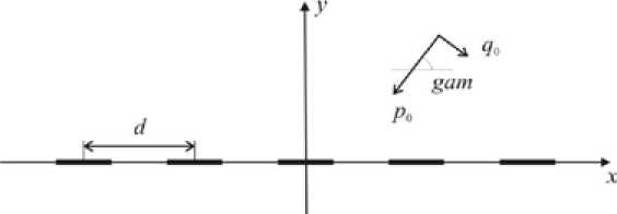
Fig. 1. The initial position of cracks in the compressive field
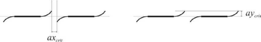
Fig. 2. Calculation termination conditions
-
d) the angle gam between coalescence plane of adjacent cracks and maximum stress direction (Fig. 1).
It was assumed that there are five cracks in isotropic elastic plane with half length equal to one located on straight line along X coordinate; p 0 and q 0 were compressive stress components at infinity ( p 0> q 0) and the angle between maximum stress p 0 and initial cracks direction is gam . The fracture growth is provided with pressure applied to the initial cracks ( e 00 × p 0 , where e 00 >0).
According to the software algorithm, the count stopped when growing fractures approached each other closer than ax crit or one of fracture wings came out from the ay crit interval (Fig. 2). These critical values were obtained during auxiliary studies covered the process of fractures interaction and coalescence on relatively small ranges.
The limitation for axcrit can be explained due to certain features of used software: the algorithm is not designed for modeling of fractures intersection. That is why the value of ax crit was chosen small enough to consider separate cracks as a jointed system. The reason for aycrit limit is due to the fact that cracks do not merge during the fracturing when they are out of ± ay crit interval.
The purpose of numerical studies was to determine the maximum distance between fracturing wells d max at which separate cracks merge into a single system, and to estimate the impact of various factors on this value.
Numerical experiments were carried out as follows:
-
a) qdp value was chosen equal to 0.5 or 0.8;
-
b) angle gam was chosen equal to 10, 30, 45, 60 or 80 degrees;
-
c) the ratio of pressure in the crack to the maximum compressive stress e 00 varied in the range from 1.2 to 10.0;
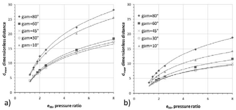
Fig. 3. Dependence of d max ( e 00 ) for different angles: a) qdp = 0.8 and b) qdp = 0.5
-
d) axcrit = 0.05; aycrit = 1
During experiments the desired value of d max was determined.
Fig. 3 shows the calculated dependence of the maximum distance d max on the e 00 when qdp value equal to 0.8 and 0.5 respectively.
Presented graphs show that with increasing pressure in the cracks there is a growth in the distance d max . According to the data obtained this growth is faster when the angle gam getting closer to the direction of one of the principal stresses. The total dependence of dmax ( e 00) is given by dmax = A ×ln( e 00)+ B with high degree of approximation and correlation coefficient R2> 0.99.
When the relation qdp is decreased, the maximum distance between wells dmax becomes smaller. Another feature is that in the non-uniform compression field this spacing is less than in the hydrostatic (or uniform) condition. With decreasing angle gam from 80° to some gamcrit , the value of dmax is reduced, and a further decrease leads to gam value growth. Fig. 4 shows the dependence of the gam crit on qdp , based on the numerical experiments results. The value of gamcrit increases linearly from 36° at qdp equals 0.5 to 44° with qdp equals 0.9; and approximate value for the critical angle is 45° when the stress state of coal measure rocks can be described as hydrostatic.
Overall, these results are consistent with the generally accepted linear fracture mechanics, which confirms the correctness of the algorithm and software program.
Fig. 5 shows a plot of d max dependent on e 00 at different qdp . The angle between the direction of the maximum principal stress and the fracture line is either equal to 1°, or close to 90°.
In this case, when the direction of cracks propagation is close to the direction of one of the principal stresses, the formation of a combined fracture system is performed at the greatest distances between fracturing wells. The maximum value of d max is observed during the cracks propagation in the less energetically favourable direction ( gam equal to 89°) which is corresponds to a minimum principal stress.
The results show a strong influence of the hydraulic fracturing pressure on the crack propagation stability in a given direction. At small pressures, which can be modeled by low pumping rates of fluid, – 80 –
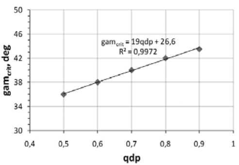
Fig. 4. The gam crit value for different qdp
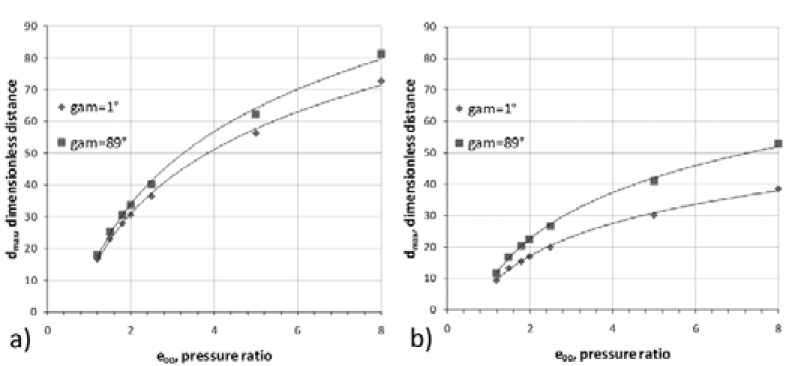
Fig. 5. Dependence of d max ( e 00 ) for principal stress directions: a) qdp = 0.8 and b) qdp = 0.5
the value of d max is approximately three times smaller than at high pressures and that is the evidence in favour of the pulsed nature of the fracturing. In order to achieve a high rate of fluid flow it is necessary to use more efficient pumps or special high-capacity hydropneumatic accumulators automatically switching on at time of fracture formation.
-
1. The algorithm for calculating the trajectory of the synchronous longitudinal hydraulic fracturing carried out in parallel wells and research software based on this algorithm were developed.
-
2. The influence of coal rocks stress state to the maximum possible distance between wells providing fractures linkage was determined. Also it is emphasized the desirability of pulsed fracturing with high rates of fluid flow in to the growing crack.
-
3. The obtained results help to design hydraulic fracture treatments in coal measure rocks in order to solve the problem of underground methane production or intensification of beds degassing.
This study was supported by the Ministry of education and science of Russian Federation and partially funded by grants from Russian foundation for basic research (projects №11-05-00390 and 12-05-31358)
-
[1] Savruk M.P. Two dimensional problems of elasticity for bodies with cracks. K.: Naukova Dumka, 1981. P. 323.
-
[2] Panasyuk V.V. The limiting equilibrium of brittle bodies with cracks. K.: Naukova Dumka, 1968. P. 246.
-
[3] Alekseeva T.E., Martynyuk P.A. // Journal of Mining Science. 1991. Vol. 27. N 2. P. 15.
-
[4] Martynyuk P.A., Sher E.N. // Journal of Mining Science. 1996. Vol. 32. N 6, P. 19.
-
[5] Martynyuk P.A. // Journal of Mining Science. 2002. Vol. 38. N 4. P. 53.
Численные исследования процесса гидроразрыва угольного пласта для эффективной дегазации метана
А. В. Патутин, П. А. Мартынюк, С. В. Сердюков
Институт горного дела СО РАНРоссия 630091, Новосибирск, Красный пр. 54
При проведении горных работ необходима эффективная дегазация угольных пластов. В статье представлен алгоритм, использующийся для расчета траектории трещины, которая формируется в результате проведения операции гидроразрыва в нескольких параллельных скважинах. Результаты численного анализа показывают, что направление распространения трещины зависит от приложенного к ней давления и напряженного состояния массива. Оценено максимальное расстояние между скважинами гидроразрыва, при котором происходит их сбойка. Полученные результаты могут быть использованы при проектировании гидроразрыва в угольных пластах с целью добычи метана либо для интенсификации дегазации углепородного массива.
