О фокусировке рентгеновских лучей клиновыми многослойными Лауэ линзами

Автор: В.Н. Пунегов
Журнал: Известия Коми научного центра УрО РАН @izvestia-komisc
Статья в выпуске: 4 (44), 2020 года.
Бесплатный доступ
Короткий адрес: https://sciup.org/149129527
IDR: 149129527
On X-ray focusing by wedge m ultilayer Laue lenses
Текст статьи О фокусировке рентгеновских лучей клиновыми многослойными Лауэ линзами
VI PUNEGBV
ОИ X HAY FHCUSIHG OY WEDGE MULTILAYER LADE LEHSES
Institute of Physics and Mathematics, Federal Research Centre Komi Science Centre, Ural Branch, RAS, Syktyvkar
The paper [1] presents theoretical results on the focusing properties of a one-dimensional multilayer wedge Laue lens (MLL). The calculations were performed using the beam propagation method for a lens that focuses X-rays with an energy of 20 keV to a spot size of less than 5 nm. The method used by the authors and the results obtained on its basis are highly questionable. In [1], it is not shown how the beam propagation method is related to the multilayer Laue lens structure, how the X-ray Laue diffraction of an aperiodic multilayer structure is described using the beam propagation method, and finally, what is the distribution of the transmission and diffraction intensities inside the MLL at an angle of X-ray beam incidence a = 8.5 mrad. Moreover, the authors [1] consider the distribution of the dielectric constant D(Xi) in the lens as a periodic trapezoidal function, while this distribution should correspond to the configuration of the Fresnel zone plate. Therefore, the purpose of this paper is to provide an alternative description of the MLL focusing based on the dynamic Laue diffraction theory and to compare the results obtained with the data of the paper [1].
Diffraction equations
Dynamical Laue X-ray diffraction in periodic media differs from diffraction in Bragg geometry [2]. One of the differences is the Pendellosung effect, when the intensities of the transmission and diffraction X-ray waves oscillate into the periodic medium. The period of such Pendellosung oscillations (Pendellosung distance) in the symmetrical Laue geometry is equal to Aq = A |cos#b| /(C |xi I), where A is the X-ray wavelength, 9p is the Bragg angle, C is the polarization factor, and
Xi is the Fourier component of the X-ray polarizability in the diffraction direction.
Direct calculations of the distribution of X-ray intensities inside the multilayer Laue lens have not yet been carried out. Such calculations, in contrast to the traditional dynamical theory [2], should be performed taking into account the spatial restriction of X-ray beams [37].
For a rigorous calculation of the intensity distribution inside the MLL, we use the Takagi -Taupin equations [8, 9] in an oblique coordinate system (Fig. 1):
5j = -^ (Z3 + A^), 3j = -ro^A/;, з = t, b indicates the corresponding layer in the period of the multilayer structure, tq = ^/(mc2) is the classical electron radius, e and m are the electron charge and mass, Nj is the atomic density, Z is the number of electrons in an atom, A/J and A/" are the dispersion corrections to the atomic amplitude.
The structure of MLL corresponds to the design of periodically alternating layers of heavy and light material according to the law of the Fresnel zone plate [ 1 ].
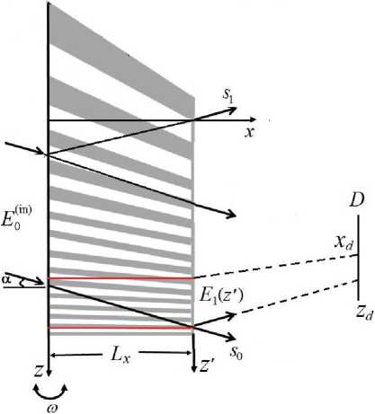
Fig. 1. Schematic representation of X-ray diffraction in a wedged multilayer Laue lens.
Рис. 1. Схематическое изображение рентгеновской дифракции в МЛЛ.
n2A2
where n is the layer number, / is the focal length of the zone plate, A is the wavelength of the incident X-ray radiation, G(x) = 1 — g x, g = 0.5/-1. The width of the n-th zone is defined as
А/ 2r

Therefore, MLL is a multilayer structure with variable period
dm^ = 2Агт(ж) = d-V- Mm^x\
4®o+i4o+l)
<5si
where d is the average MLL period, Adm(ai) is the mismatch of the period with the number m (m = 2n) relative to the average period. The relative mismatch of the MLL period can be written as
*aifDwEi(r]; s0,si), г (g + Ф(^Si)) Eg(g;so, si)+ ^aifowEg^q; sq, si),

^dm (x) d
— el^x, z)G(x).
where Едд (g; s0, si) are the amplitudes of the transmission Eg and diffraction Ei of X-ray wave, Ф(бо181) = 2rrg(so, Si) sin Ов/d, x(so, si) = A(so, s\)/d is the relative mismatch of the MLL period, d is the average MLL period, ад = тгхо/А, ai = Cttxi/A, g = 2тгш 8ш(26*в)/А is the angular parameter, w is the deviation of the X-ray beam from the Bragg angle 9 в, Jdw is the statistic Debye-Waller factor. The Fourier coefficients of X-ray polarizability for a structure with a two-layer period in the direction of transmission xo and diffraction xi are written as
Xb =
Xtdt + Xfcdb Xt ~ Xb .
------7-----, XI = -------sin d 7Г

Here xt,b and dt,b the Fourier coefficients of polarizability and thicknesses of the upper (t) and lower (b) layers of the period of the multilayer structure. X-ray polarizabilities of chemical elements are calculated using table values of optical constants: Xj = Wj + iPj\
The structure of MLL, the geometry of X-ray diffraction, and the characteristics of X-ray radiation in numerical simulation corresponded to the parameters used in [1]. The total number of MLL layers is A = 5822, the number of layers illuminated by the X-ray beam was 5500 (M, = 2750 is the number of periods) [1]. For hard X-ray radiation (wavelength is 0.062 nm') according to the law of the Fresnel zone plate, the focal length corresponds to / = 1.25 mm. The size of the first zone is Ari = 13.9 nm, the last zone is /Хл^ц^ = 1.8 nm. For the width Lz = 16.7 gm of the incident X-ray beam on the MLL, the minimum illuminated Laue lens period is 3.65 nm, and the maximum one is 17 nm. The average MLL period is d = Lz/Mz = 6 nm, which corresponds to a Bragg angle of 5.2 mrad. The maximum mismatch of the MLL period is 11 nm, the minimum mismatch is 2.3 nm. The parameter g = 0.4 mm-1, the coefficient G(x) varies from 1 to 0.994. The map of relative mismatches of the MLL period is shown in Fig. 2.
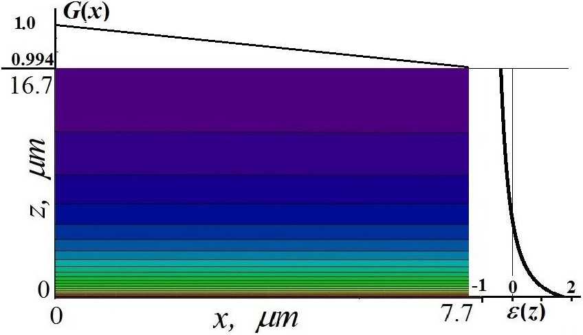
Fig. 2. Map of the relative mismatch of the MLL period ®ы| on a linear scale. The ratio of e(®t,») values between adjacent lines is 0.1. The maximum value of the relative period mismatch is ^«(Жцй) = 1.833 (red color) and the minimum value is а^п^ш = —0.394. (purple color).
Рис. 2. Карта относительного рассогласования периода МЛЛ е(х, г) в линейном масштабе. Отношение значений е(х, г) между соседними линиями 0.1. Максимальное значение относительного рассогласования периода етах(х> ^ = 1-833 (красный цвет) и минимальное значение ^^^[х,;^) = —0.394 (фиолетовый цвет).
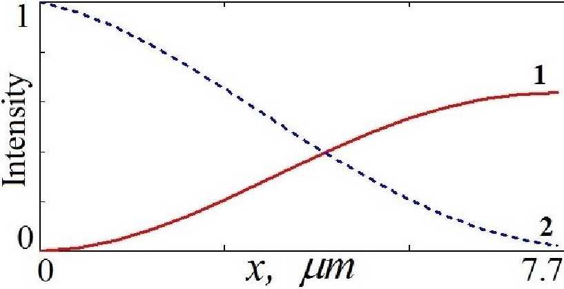
Fig. 3. The intensity distribution of the diffraction (1) and transmission (2) X-ray waves inside the W/SiC MLL for an X-ray wavelength of 0.062 nm.
Рис. 3. Распределение интенсивности дифракционной (1) и проходящей (2) рентгеновской волны внутри МЛЛ W/SiC для длины рентгеновской волны 0.062 пт.
The results of numerical simulation of the intensity distribution of the X-ray fields inside the MLL are shown in Fig. 4 — Fig. 7. The intensity maps of the X-ray wave fields are given on a linear scale, the ratio between adjacent lines is 0.1. Red color refers to the maximum value of intensity, purple color corresponds to the minimum intensity.
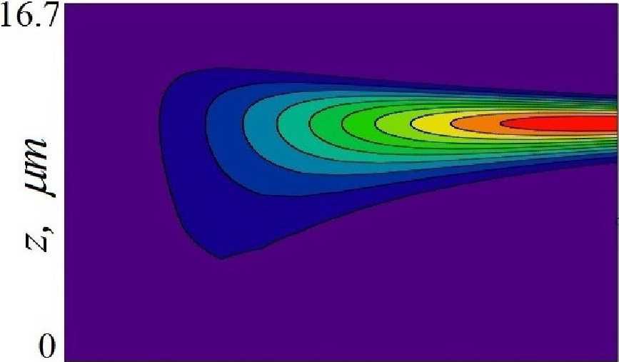
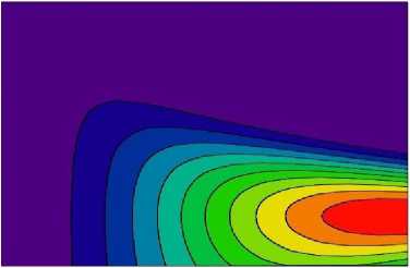
Fig. 4 and Fig. 5 shows the intensity distributions of the diffraction and transmission X-ray beam inside the MLL for angular deviation w = 0. The intensity incident on the left face of the MLL is Iq = |e,^) | = 1 (Fig. 1). The maximum diffraction intensity la = 0.64 is concentrated near the right face of the MLL (red spot in Fig. 4 and curve 1 in Fig. 8). In this region, the transmission intensity is It й 0 (purple spot in Fig. 5, curve 2 in Fig. 8).
X-ray fields inside a wedge multilayer Laue lens
The calculations of the X-ray intensity distribution inside the MLL were performed using equations (1). The numerical algorithm of the “half-step derivative” was applied [7]. In addition, X-ray fields were calculated on the basis of the two-dimensional Takagi - Taupin equations in the Cartesian coordinate system using the Runge - Kutta method [10], as well as two-dimensional recurrence relations was employed [3, 4]. All these methods led to the same result, which ultimately was a guarantee of the correctness of the calculations.
X-ray diffraction was calculated in MLL, consisting of alternating layers of tungsten (Ж) and silicon carbide (SVC) [1]. In the calculations, we used the optical constants oftungsten xw = (—1.596 + г 0.125) ■ 10-3 and silicon carbide xw = (—0.334 +■ i 0.00092) • 10-3 for an X-ray energy of 20 keV [11-13].
The lateral size of the MLL is Lx = 7.7 цт (Fig. 1), which corresponds to half the Pendellosung distance. This length of the lens gives the maximum intensity of the diffraction beam at the exit from the right face of the MLL (Fig. 3). The intensity distribution of the transmission and diffraction X-ray beams inside the MLL is shown in Fig. 3.
o x, pm 7.7
Fig. 4. The intensity distribution map of the diffraction X-ray beam inside the MLL for angular deviation ш = 0 (the X-ray incidence angle is а = 9в = 5.2 mrad for the average MLL period d = 6 nm).
Рис. 4. Карта распределения интенсивности дифракционного рентгеновского пучка внутри МЛЛ для ш = 0 (угол падения рентгеновского пучка а = 9в = 5.2 mrad для среднего периода МЛЛ d = 6 пт).
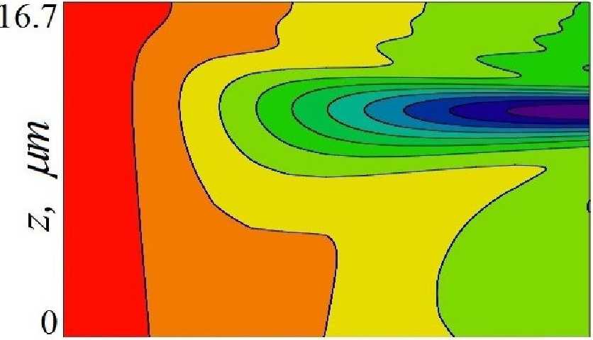
Fig. 5. The intensity distribution map of the transmission X-ray beam inside the MLL for angular deviation ш = 0 (the X-ray incidence angle is a = 9b = 5.2 mrad for the average MLL period d = 6 nm).
Рис. 5. Карта распределения интенсивности проходящего рентгеновского пучка внутри МЛЛ для да = 0 (угол падения рентгеновского пучка а = 0в = 5.2 mrad для среднего периода МЛЛ d = 6 пт).
By increasing the angular deviation (w = 1.7 mrad, a = 9b + w = 6.8 mrad (Fig. 1)), the maximum diffraction intensity Id = 0.64 does not change. The diffraction spot increases and shifts downward along the right face of the MLL (Fig. 6, Fig. 9, curve 1). The intensity of the transmission beam has a minimum value of It « 0 (Fig. 9, curve 2).
16.7
I
N"
x, цт пл
(Fig. 7). Thus, the information on focusing by the wedge multilayer Laue lens presented in [1] is incorrect. Focusing of the diffraction beam for the angle of incidence a = 8.5 mrad, as presented in [1], is not possible, since the Laue X-ray diffraction conditions are not satisfied at this incident angle.
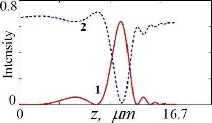
Fig. 8. The intensity distribution of the diffraction (1) and transmission (2) X-ray wave coming out of the W/SiC MLL. The angular deviation is to = 0 mrad.
Рис. 8. Распределение интенсивности дифракционной (1) и проходящей (2) рентгеновской волны, выходящей из МЛЛ W/SiC с угловым отклонением ш = 0 mrad.
Fig. 6. The intensity distribution map of the X-ray diffraction beam inside the MLL for angular deviation to = 1.7 mrad, the X-ray incidence angle is a = 0в + w = 6.8 mrad.
Рис. 6. Карта распределения интенсивности дифракционного рентгеновского пучка внутри МЛЛ для ш = 1.7 mrad, угол падения рентгеновского пучка а = 0в + ш = 6.8 mrad.
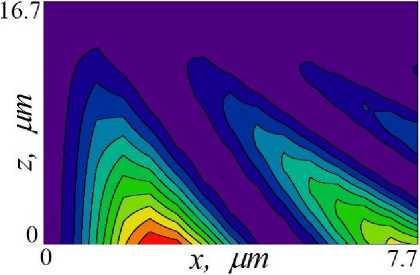
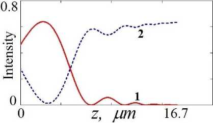
Fig. 9. The intensity distribution of the diffraction (1) and transmission (2) X-ray wave coming out of the W/SiC MLL. The angular deviation is to = 1.7 mrad.
Рис. 9. Распределение интенсивности дифракционной (1) и проходящей (2) рентгеновской волны, выходящей из МЛЛ W/SiC с угловым отклонением ш = 1.7 mrad.
Fig. 7. The intensity distribution map of the X-ray diffraction beam inside the MLL for angular deviation to = 3.3 mrad, the X-ray incidence angle is a = 0b +w = 8.5 mrad.
Рис. 7. Карта распределения интенсивности дифракционного рентгеновского пучка внутри МЛЛ для и = 3.3 mrad, угол падения рентгеновского пучка а = 0В + to = 8.5 mrad.
However, a further increase in angular deviation to a value of 3.3 mrad (the X-ray incidence angle is о = 9+w = 8.5 mrad) disturbs the diffraction condition in the MLL (Fig. 7). The maximum value of the diffraction intensity I(i = 0.065 decreased by 10 times and was not placed at the right face of the MLL, but located inside the lens. In this case, the Pendellosung effect is disturbed, X-ray diffraction is suppressed, and the maximum value of the reflected intensity is 0.04 at the bottom of the MLL
Focusing of diffraction intensity
The amplitude Si (c') of X-ray wave exiting from the right face of the MLL propagates outside the multilayer structure according to the Fresnel-Kirchhoff law [14] '
Ei^xd^i) = cos 9в
j dz'P^Xd, Zd — cos 9bz')El(z'), where Ei(xd^d) is the amplitude of the diffraction X-ray wave in the plane of the detector (Fig. 1), l’\x,:.') = (^Хх)-хЛ ехр(гтгс2/(Аж)) is the propagator of X-ray wavefield [14].
о xd, тт юо
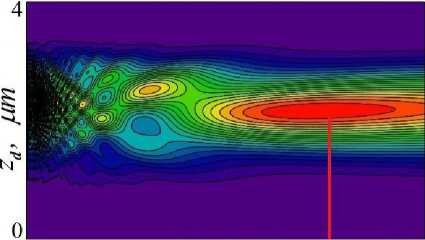
Fig. 10. The distribution map of the focused intensity of a diffraction beam coming out of the MLL in the case of ш = 0.
Рис. 10. Карта распределения сфокусированной интенсивности дифракционного пучка, вышедшего из МЛЛ в случае w = 0.
this optical principle, in the aperiodic structure, the Bragg diffraction condition will be satisfied in a layer of thickness /i, if in the equations (1) g + Ф(во, si) < тг/Zi or from here, /i « 0.5 ^/(cos^bw + f sin 9q\ where e is the average relative mismatch of the period in the layer /1, If the mismatch of the layers is zero, that is, the period of the multilayer structure is constant, then ly -a co. In other words, diffraction will be observed if Bragg’s law is satisfied:
2(d ± Ad) sin (9b Tw) = A.
Even when the angular deviation w = 0, X-ray diffraction is performed in a narrow area of the MLL with a period d-f- Adm = d (1 Ф|т) until the phase changes of the X-ray waves remove the beam from the diffraction condition. The width of this area is equal to the thickness of the phase layer /j. In our case, at w = 0Д = 0.148, the size ofthe diffraction area/i « ^Д^Нби^в) = 3.9/zm, which is consistent with the width of the diffraction beam 3.8 ym (Fig. 11). By changing the diffraction angle by @ = 1.7 mrad, the size of the diffraction area is /1 = 8.6 pm, however, the size of the exiting diffraction beam is 7.7 pm (Fig. 9). This is due to the fact that not all MLL periods ofthe “phase layer” ly = 8.6 pm participate in diffraction. At the angle of the incident beam a = 8.5 mrad [1], under diffraction conditions there is only one, the smallest MLL period, and diffraction from the /1/2 layer is extinguished by the “antiphase layer” l^ [16, 17]. ' " ' ■ -
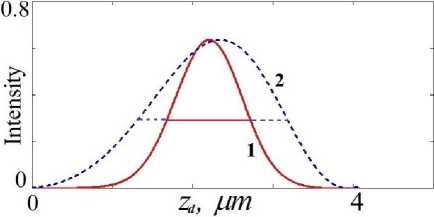
Fig. 11. The normalized intensity distribution of the focal spot (1) and the outgoing X-ray beam from the MLL (2). ......
Рис. 11. Нормированное распределение интенсивности фокусного пятна (1) и выходящего рентгеновского пучка из МЛЛ (2).
In Fig. 8 the map of the focused intensity of diffraction beam exiting from the MLL at ж 0 depending on the position of the detector ta is represented. The distance to the middle of the focal spot shown in Fig. 8 by the red line is 73 mm, while according to the law of the Fresnel zone plate it should be 1.25 mm. Fig. 9 shows the normalized intensity distributions of the focal spot (curve 1) and the exiting X-ray beam from the MLL (curve 2). The focal spot size at half full intensity is 960 nm, which does not agree with the value of 5 nm [1].
Features of X-ray diffraction by aperiodic structures
Calculations performed using rigorous equations of the dynamical theory show that diffraction focusing by multilayer structures is very different from focusing by Fresnel zone plates. The supposition that wedged multilayer Laue lens is more effective than flat MLL is rather controversial [15]. Wedge-shaped layers create inhomogeneity not only in thickness 3, but also in width ж of the multilayer structure (Fig. 1), thereby leading to a disturbance of the Pendellosung effect in MLL. In the diffraction equations (1), the phase changes caused by the mismatch of the MLL period are determined by the parameter у + Ф(8о, б1). In papers [16, 17], X-ray diffraction in a structure with the linear lattice period variation was considered, and the optical principle of "phase layers” was developed to describe diffraction. According to
Conclusion remarks
Thus, in the present work, for the first time, the results of numerical simulation of X-ray wave fields inside a wedge multilayer Laue lens are presented. Due to the mismatches ofthe MLL period, the diffraction condition will not cover the entire volume of the lens, but only its insignificant area. This area in Fig. 1 is schematically restricted by red lines. The size of this area depends on the average relative mismatch Cof the mismatch period and the incidence angle of the X-ray beam a. Consequently, the intensity distribution ofthe X-ray wavefields inside the MLL is more likely related to the “collimation” of the X-ray beam, and not to its focusing. Moreover, such “collimation” is not connected to the configuration ofthe Fresnel zone plate [15]. Also it was shown that for the incidence angle of the X-ray beam a = 8.5 mrad on the MLL, the Laue diffraction condition is not satisfied, therefore, the results of [1] are erroneous.
