Omni Directional Antenna Assisted Scheme to Minimize Redundancy in Wireless Sensor Networks

Author: Tarun Dubey, O.P. Sahu
Journal: International Journal of Computer Network and Information Security(IJCNIS) @ijcnis
Article in issue: 4 vol.5, 2013.
Free access
Wireless Sensor Networks (WSNs) incorporate smart antennas for information propagation to offer connected coverage with reduced interference. This paper presents an omni directional antenna assisted scheme for WSNs to reduce network redundancy besides offering connected coverage. The directivity of an omni directional antenna outfitted on a sink node is exploited to reduce network redundancy and at the same time the connectivity of sensor nodes with the sink node is retained. The relationship between lobe count, beam width, rotation angle and directivity of an omni directional antenna in context of sensor networks is also discussed. Simulation results show a significant reduction in overall network redundancy if the rotation angle of the omni directional antenna fitted on the sink node is minimized from 360° to 30°
Localization, omni directional antenna, redundancy, sensor node, sink node, WSNs
Short address: https://sciup.org/15011184
IDR: 15011184
Text of the scientific article Omni Directional Antenna Assisted Scheme to Minimize Redundancy in Wireless Sensor Networks
Published Online April 2013 in MECS
Wireless Sensor Networks (WSNs) are a collection of thousands of self powered tiny sensor nodes to monitor temperature, pressure, humidity, vehicular movement, noise levels, lighting conditions and other physical phenomena’s of interest [1]. Sensor nodes are equipped with memory and a transreceiver and adopt mechanisms such as seismic, magnetic, thermal, visual, infrared, and acoustic radar [2], [3], [4] for sensing and support a wide spectrum of applications in military, medical, meteorological, agricultural, industrial and aerospace areas [5], [6]. Lot of work [7], [8], [9], [10] has been dedicated in the past years to quantify the impact of WSNs for next generations in order to efficiently resolve the associated challenges like connectivity, power consumption, node failure, data exchange, deployment, fault tolerance, localization and redundancy [11], [12]. In recent years the rapid developments in antenna technologies have made it possible for sensor nodes to be equipped with smart antennas. It is important to analyze how much performance gain antennas (either unidirectional or omni directional) can bring to sensor networks to overcome the above discussed operational challenges. Various antenna assisted schemes for sensor networks offer performance gains along with benefits of reduced interference and increased spatial reuse [13] but cannot be directly applied to adhoc as well as sensor networks under the proposed analytical models due to the varying traffic patterns. In adhoc networks the patterns are many to many, while in sensor networks all sensor nodes send their data to a sink node (which is a many to one traffic pattern). Sensor networks are a class of information systems that aim to change the way in which people observe and interact with their environment, they comprise of low cost unattended groups of densely placed sensor nodes that observe, communicate (often using wireless medium), and coordinate to collectively achieve a task. It is desirable for such networks to be redundant to some extent, by distributing densely deployed sensor nodes to obtain more accurate and complete readings of observed events. This paper investigates the performance of an omni directional antenna for WSNs to provide higher levels of connectivity with reduced network redundancy. The proposed scheme assumes the deployment of sensor nodes along with a sink node which is outfitted with an omni directional antenna in a fixed sized network. The main contribution of this paper is the evaluation of network redundancy, where an event or phenomenon is covered or monitored by multiple sensors. The reduced redundancy is evaluated over a general network model in consideration with technical facets like rotation angle, lobe count and beam width of an omni directional antenna as compared to other schemes proposed in previous studies [14], [15]. To the best of our knowledge, we are the first to provide a basic scheme that has been leveraged in all proposed antenna assisted schemes for sensor networks. The rest of the paper is organized as follows. Section 2 provides basic definitions and categorizes different types of redundancy. The features of omni directional antenna in context of WSNs are explained in Section 3. The proposed network model and simulation results are discussed in Section 4 and Section 5. In Section 6 we draw our conclusions.
-
II. DEFINITIONS
Redundancy is often associated with the provision of adding duplicate resources to produce similar results, in WSNs redundancy is both friend and foe and challenges the researchers to emphasize more on the positive aspects. It is evaluated to increase data accuracy, sensing reliability, system lifetime and security keeping in mind the fact that high redundancy indicates a poor network usage with high energy consumption [16]. Several explanations of redundancy are presented in the literature [17] that covers issues like, sensing, coverage, communication, measurements and data storage. Few definitions for redundancy are selected and summarized as follows.
-
A. Spatial Redundancy
It is described using a variety of metrics, [18] it provides information from a specific location through different sources in dense WSNs. It presumes resources like sensor motes, communication connections and mathematical models for cross monitoring of duplicated information.
-
B. Physical Redundancy
Often known as direct redundancy, it is observed to ensure reliability of WSNs in order to measure a desired variable over a specific location with more than one sensor node [19]. Supplementary sensors may also be used for collection of data during the aggregation process.
-
C. Analytical Redundancy
It is simplification of physical redundancy; the sensed information is obtained only from virtual sensor nodes (software based sensors) for describing an expected behavior using live data received from neighboring sensor nodes. This approach utilizes a mathematical model [20] to predict the value of one sensor node by considering the past and present values of its neighbors.
-
D. Temporal Redundancy
It is defined as performing a specific task more than once in a time skewed manner for increasing network reliability. It is mainly observed in video surveillance [21], and does not find much scope in context to dynamic WSNs since the parameters change rapidly with respect to time.
-
E. Information Redundancy
It refers to the use of redundant data (extra bits), to reconstruct the lost information. It implies the use of extra information for error detection and recreation of the original message without link retransmission [22].
-
III. OMNI DIRECTIONAL ANTENNA FOR WSNs
In this section we provide a broad overview of the antenna systems, associated problems, and solution approach for utilizing the benefits of omni directional antenna systems in sensor networks [23]. We would like to point out that in sensor network based implementations both the omni and directional modes are used to transmit or receive messages since the transmission cost of each is proportional to the coverage area. For an omni directional antenna, the electromagnetic energy of the signal is spread over a large region of space this facilitates the omni directional antenna to radiate and receive electromagnetic waves from all directions (360°). The omni directional antenna can receive signals from all directions if the sender is within its communication range, however with a directional antenna this is not possible due to the problem of connected coverage. In cases of complex network topologies more than one directional antenna per sensor is required to achieve optimized network performance, this adds to cost and creates other challenges too. However connectivity in WSNs may be established using either omni directional or directional antennae as discussed earlier, it is of interest to design efficient schemes that minimize the overall transmission cost while at the same time maintains network connectivity with reduced redundancy. The optimal deployment of nodes to achieve full coverage and connectivity in wireless networks has long remained a fundamental problem of engineering interest. Besides the immediate benefit of signal transmission over a 360° angle, lower cost and better network management in random deployments is also offered by an omni directional antenna. The placement of an omni directional antenna in a wide variety of environments allows maintaining a low profile and also preserves the input impedance and radiation behavior; therefore it can also be used for ground sensor networks. Despite its relatively low radiation gain and efficiency, it has shown that additional improvements if made can reduce the interference and lead to the improvement in network capacity besides offering low redundancy. Omni directional antennas if oriented vertically can be widely used on the surface of earth because they radiate equally in all horizontal directions, while the power radiated drops off with elevation angle so little radio energy is aimed into the sky or down towards the earth thus reducing the wastage. Higher gain omni directional antennas radiate less energy at higher and lower elevation angles and more in the horizontal directions. They are generally realized using collinear dipole arrays consisting of half wavelength dipoles with a phase shifting method between each element to ensure that the current in each dipole is in phase. Omni directional antennas are widely used for majority of wireless applications such as radio broadcasting, cell phones, walkie talkies, wireless computer networks, cordless phones and global positioning system (GPS) base stations. Most of the previous studies on the fault tolerant design of WSNs consider the sensor nodes to be equipped with omni directional antennas with the objective to assign transmission power to the nodes such that the network remains connected and power consumption is minimized. In a fault tolerant network there are some disjoint paths between every two nodes, for data collection it is necessary that every sensor node has same number of disjoint paths with the sink node.
Although directional antenna assisted sensor networks have a fundamental advantage in terms of longer communication range and they may substantially improve the performance of wireless networks in near future, but to exploit these advantages, effective communication paradigms are yet to be developed. In our proposed scheme, we have considered an optimal omni directional antenna pattern for a wireless sensor network, the omni directional mode is used for a sensor to communicate with the sink or vice versa and any sensor within the reachable radius of the sink node will receive the signal so as to cover a particular region within its circular range.
-
IV. THE NETWORK MODEL
Sink node is the destination of information for collecting sensed data either directly (mobile sink) or indirectly (static sink). The collected data is made available to interested users by various means. The network model depicted in Fig. 1 ensures the supervision of a given area using a sink node, to collect information from the network considering event detection. The communication is initiated by the occurrence of a pre specified type of event. Once an event occurs, it has to be reported to the sink node outfitted with a rotatable omni directional antenna with a rotation angle α, sensor nodes have an event radius Re and are the sources of detected events. Sensor nodes are characterized by their coverage range R c and the range of sink node is categorized by the directivity given as,
D = 4π/Ω (1)
The directivity factor also includes the gain G and antenna efficiency η, the applicable relationship is
G = η x D (2)
Since the transmitted power P t and the gain G are functions of the omni directional antenna on the sink node the distance between the two nodes can also be determined according to Friis transmission relationship [24]. The gain G is the ratio between the radiation intensity F max generated in the main direction to the radiation intensity F which an omni directional antenna generates at the same input power. Let N Total denote the number of sensor nodes within a particular event area. Therefore, N (N ∈ {1 … .N Total }) represents the number of active nodes in a network. In our network model we assume that the radiation intensity F is same and equal to network reporting frequency F, defined as the number of messages generated per unit of time within the network in order to report a detected event. Hence, for N active reporting nodes, the reporting frequency must be set equal to
F s = F/N (3)
The N reporting nodes keep generating reports at a rate FS until an event is detected. The desired event reliability R (N) is the number of data packets required by the sink to consider the event as reliable. An event is said to be reliably reported when the required information accuracy is achieved at the sink node. Once the sink node receives R (N) reports, it instructs the sensor node to stop the event reporting. We analyzed the impact of rotation angle of an omni directional antenna on the performance of wireless sensor network. The basic idea is to calculate the number of lobes, L with respect to the beam angle Ω, since
L = 360°/Ω (4)
The coefficient of sink node K can be obtained by utilizing the relation
K= 360°/2π (5)
Sensor Node
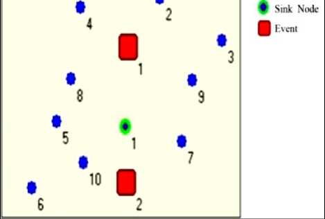
Figure 1: Wireless sensor network model
The omni directional antenna fitted on the sink node covers a circular area. The coverage radius of the sink node is determined by the beam angle Ω and the lobes L of the omni directional antenna. The sink node is stationary and the number of formed lobes, L depends totally on the rotation angle. The observed patterns of the omni directional antenna for different values of α are shown in Fig. 2. The patterns highlight the significant reduction in number of lobes as the value of α is reduced from 360° to 30°. If the omni directional antenna extends its communication range, the neighboring nodes in its communication range may also increase. Therefore omni directional antenna does not alter the important characteristics such as the degree, diameter, and average path length. Moreover since the diameter is one therefore the nodes that lie within the strongly connected diameter can potentially transmit at the same time in all directions without much interference. The omni directional antenna enables the sensor nodes and sink nodes to cover a more far off region with the same level of energy consumption if both transmission and reception are uniform in all directions.
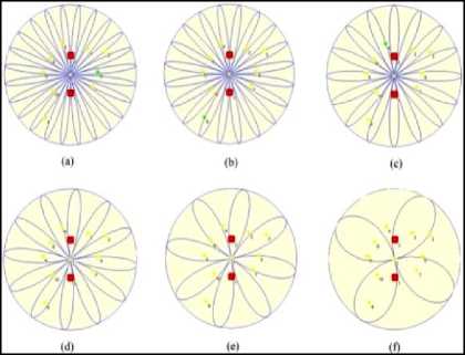
Figure 2: (a) α =360°, L=24 (b) α=180°, L=20 (c) α=90°, L=16 (d) α = 60°, L=12(e) α=45°, L=8 (f) α=30°, L=4
-
V. SIMULATION RESULTS
The proposed scheme involves the deployment of one sink node along with other sensor nodes. The raw data collected by the individual sensor nodes is fused and forwarded to the sink node to provide an interface with the outside world. The parameters listed in Table I have been simulated using SNetSim [26]. The simulator provides the functionality to set the deployment area prior to sensor node and sink node deployment. The sensor nodes and the sink node are static hence data forwarding decisions depend only on location of nodes and the positioning of sink node. The omni directional antenna plays a central role and the complexity is concentrated on the sink node where it rotates while little overhead is imposed on sensor nodes. The decrease in α, facilitates the transmitted data to the sink node with less redundancy and the same level of redundancy can be achieved for different values of lobe count L, the lower the value of L is, the greater is the beam angle Ω, in order to attain less redundancy. The spatial radiation behavior of an omni directional antenna is described by its radiation pattern (normally in the far field). Only an omni directional antenna would exhibit the same radiation in every spatial direction, but it cannot be implemented for any specified polarization and is therefore more suitable for a sensor network model. The directional antenna if applied to the sink node implies a narrow angular speed or angle of arrival (AoA), however in mesh networks or WSNs the angular speed of propagation and channel is quite different which implies that directional antennas may not be much effective for such networks. More essentially the ability to adopt multipath and angular distribution is largely limited by the small size of nodes; therefore the full beam formed by the directional antenna has limited effect on the performance as compared to omni directional antenna as even a low gain omni directional antenna provides a strong signal in every direction. If the sensors lie in a common oriented plane then the use of omni directional antenna per sensor will also provide robust localization to form a wireless network of strongly connected sensor nodes.
TABLE I. SIMULATION PARAMETERS
|
Parameter Name |
Value |
|
Area |
1000 m × 500 m |
|
Sink |
1 |
|
Events |
2 |
|
Range |
200 m |
|
Distribution |
Normal |
|
Protocol |
Gossip |
|
Nodes |
10 |
For the graph shown in Fig.3 as the rotation angle decreases, the beam angle increases, resulting in the decrease in overall redundancy within the wireless sensor network.
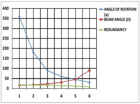
Figure 3: Redundancy with respect to α and Ω
For the graph shown in Fig.4 the coefficient of sink K decreases with decrease in the lobe count and results in achieving a similar level of reduced redundancy within the wireless sensor network.
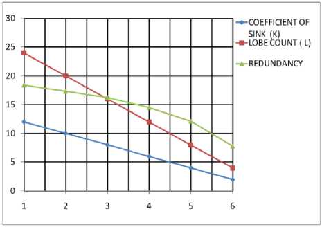
Figure 4: Redundancy with respect to L and K
-
VI. CONCLUSIONS
In this paper, we proposed a new scheme assisted by an omni directional antenna to minimize redundancy in WSNs. Our finding lead us to conclude that reducing the rotation angle α, significantly reduce the lobe count L for an omni directional antenna and provides low redundancy. The proposed scheme delivers better performance with a much simpler hardware and software architecture. Although our focus in this paper is on redundancy, it is conceivable that such an approach can be exploited as a future work to simplify tasks, such as distribution, programming, deployment and localization. At this initial phase, we have neglected the energy consumption of nodes and antennas since this makes sense only if the nodes and antenna both use the phased array technology. To summarize, we have analyzed the performance of an omni directional antenna through the use of a more general wireless sensor network model. Simulation results show that the proposed scheme achieves low redundancy. Further utilizing this new scheme, the infrastructure of sensor networks can also be improved provided the functionality of sensor nodes is also be expanded such that each sensor node can detect the location of its neighboring node independently to improve localization.
References Omni Directional Antenna Assisted Scheme to Minimize Redundancy in Wireless Sensor Networks
- D. Estrin, R. Govindan, J. Heidemann and S. Kumar, "NextCentury Challenges: Scalable Coordination in Sensor Networks," Proc. of the ACM,1999, pp. 263-270.
- I. F. Akyildiz, W. Su, Y. Sankarasubramaniam and E.Cayirci, "Wireless Sensor Networks: A Survey," Computer Networks, 38,2002, pp.393-422.
- J. Hill, R. Szewczyk, A. Woo, S. Hollar, D. Culler and K. Pister, "System Architecture Directions for Networked Sensors" Proc. of the 9th International Conference, ASPLOS IX 2000, pp. 93-104.
- I. F. Akyildiz and W. Yen, "Group Synchronization Protocols for Multimedia Networks," IEEE Journal of Selected Areas in Communications, vol.1, no.1, 1996.
- V. Manfredi, M. Crovella and J. Kurose. "Understanding Stateful vs. Stateless Communication Strategies for Ad hoc Networks," Proc. of the 17th Annual International Conference on Mobile Computing and Networking ,2011.
- L. Song, Z. Han, Z. Zhang, and B. Jiao, "Non cooperative Feedback Rate Control Game for Channel State Information in Wireless Networks," IEEE Journal on Selected Areas in Communications, Special Issue on Game Theory in Wireless Communications, vol.30,no.1, 2012, pp.188-197.
- W. Saad, Z. Han, T. Basar, M. Debbah and A. Hjrungnes,"Network Formation Games Among Relay Stations in Next Generation Wireless Networks," IEEE Trans. on Communications, vol.9,no.9, 2011,pp. 2528-2542.
- P. Saffo, "Sensors: The Next Wave of Innovation," Communications of the ACM, vol.40, no.2, 1997, pp.92-97.
- Li. Jiang, D.Y. Liu, and B. Yang, "Smart Home Research," Proc. of the International Conference on Machine Learning and Cybernetics, 2 ,2004 , pp.659-663.
- J.R. Durrett, L.J. Burnell, and J.W. Priest, "A Hybrid Analysis and Architectural Design Method for Development of Smart Home Components," IEEE Wireless Communications, vol,9,no.6, 2002,pp. 85-91.
- A. Prayati, F. Kerasiotis, C. Antonopoulos, S. Giannoulis, T. Stoyanova and G. Papadopoulos, "An Overview of Development Problems in WSNs Pervasive Computing Technologies for Healthcare," Proc. of the 3rd International Conference on Pervasive Healthcare, 2009, pp.1-4.
- A. Mojoodi , M. Mehrani , F. Forootan and R. Farshidi, "Redundancy Effect on Fault Tolerance in Wireless Sensor Networks," Global Journal of Computer Science & Technology,vol. 11,2011, pp.35-39.
- D. Lal, T. Joshi, and D. Agrawal, "Localized Transmission Scheduling for Spatial Multiplexing Using Smart Antennas in Wireless Ad hoc Networks," IEEE LANMAN ,2004.
- P. Gupta and P. R. Kumar, "The capacity of wireless networks," IEEE Transactions on Information Theory, vol.46 no.2, 2000, pp.388-404.
- M. Grossglauser and D. Tse, "Mobility increases the capacity of wireless adhoc networks," IEEE/ACM Trans. Networking, vol. 10, no.4, 2002, pp.477-486.
- B. Carbunar, A. Grama, and J. Vitek, "Redundancy and Coverage Detection in Sensor Networks," ACM Trans. on Sensor Networks, 2,2006, pp.94-128.
- S.J. Park, R. Vedantham, R. Sivakumar and I.F. Akyildiz, "A Scalable Approach for Reliable Downstream Data Delivery in Wireless Sensor Networks," Proc. of the 5th ACM International Symposium on Mobile Adhoc Networking and Computing, 2004, pp.78-89.
- R. Iyengar, K. Kar and S. Banerjee, "Low coordination Topologies for Redundancy in Sensor Networks," Proc. of the 6th ACM Annual International Symposium on Mobile Adhoc Networking and Computing, 2005,pp. 332-342.
- D.S. Shim and C.K. Yang, "Method of Detecting and Isolating Fault in Redundant Sensors, and Method of Accommodating Fault in Redundant Sensors using the Same," USPTO ,2008.
- D.I. Curiac, C. Volosencu, A. Doboli, O. Dranga and T. Bednarz, "Discovery of Malicious Nodes in Wireless Sensor Networks using Neural Predictors," WSEAS Trans. on Computer Research,vol. 1, no.2, 2007, pp.38-44.
- T. He, S. Krishnamurthy, J.A. Stankovic, T. Abdelzaher, L. Luo, R. Stoleru, T. Yan and L. Gu, "Energy-Efficient Surveillance System Using Wireless Sensor Networks," Mobisys, 2004,pp.270-283.
- O.B. Akan and I.F. Akyildiz, "Event to Sink Reliable Transport for Wireless Sensor Networks," IEEE/ACM Trans. on Networking,vol.13,no.5, 2005,pp.1003-1016.
- K. Balman and E. Jordan, "Electromagnetic Waves and Radiating Systems," Prentice Hall, New Jersey,1968.
- Kraus and Fleisch, "Electromagnetics," 5th edition., McGraw Hill, 1999.
- A.M. Kermarrec and M.V. Steen, "Gossiping in Distributed Systems," Operating Systems Review, ACM SIGOPS, vol.4,no.15,2007, pp.2-7.
- http://www.dho.edu.tr/enstitunet/snetsim/index.htm
