On Statistical Behavioral Investigations of Body Movements of Human Body Area Channel

Author: Sukhraj Kaur, Jyoteesh Malhotra
Journal: International Journal of Computer Network and Information Security(IJCNIS) @ijcnis
Article in issue: 10 vol.8, 2016.
Free access
A statistical characterization of body surface to external communication of Body Area Network is investigated for movement of human body in different directions i.e. 00, 900, 1800 and 2700, with respect to the transmitting antenna. The NICT's statistical model is used to carry out measurement in ultra-wideband (UWB) range. The important parameters that capture the variability of the delay profile over the channel e.g. mean delay spread and RMS delay spread of power delay profile (PDP) is presented. The probability density (PDF) and cumulative distribution (CDF) function of the output signal to noise ratio (SNR) have been computed. The performance of Selective Rake (S-Rake) and Partial rake (P-Rake) receiver structure that employs maximal-ratio combining (MRC) is investigated for varying number of fingers taps.
Channel Model, IEEE 802.15.6, Rake Receiver, Ultra wideband (UWB), Wireless Body Area network (WBAN)
Short address: https://sciup.org/15011592
IDR: 15011592
Text of the scientific article On Statistical Behavioral Investigations of Body Movements of Human Body Area Channel
Published Online October 2016 in MECS DOI: 10.5815/ijcnis.2016.10.04
As the world population increased, so is the number of the aged population who need continuous medical care and nursing. As a result the working load on the medical team becomes heavier. The situation is overwhelm by the growing number of patients suffering from disease like cancer, heart disease etc. who need urgent diagnosis and treatment at early stage. The employing of wireless technology in medical and health care services can provide a high quality medical support which can support early detection of abnormal conditions and prevention of its serious consequences.
Wireless Body Area Network (WBAN) is the emerging field of the technology in which the light-weight, smallsize and ultra-low power sensors are implanted or placed on the surface of the body which measures the physiological signs of the patient’s body. The control unit (CU) which is the most powerful sensor present on the body collects the information from different sensors and forwards it to some smart device like mobile phone of the patient. This smart device then via internet can forward the information to the medical team which can trigger the treatment procedure in return [1], [11]. So WBAN can help the doctors to look after more number of patients continuously from far location, which will enhance their efficiency. Moreover it provides comfort to the patient by enhancing their mobility without constraining the activities of the wearer [1].
In 1996, Zimmerman is the first to pronounce the term Personal Area Network (PAN) in which he mostly addresses the intra-body communication [2]. Later the term PAN is modified to the Body Area Network (BAN) which considers the communication around the human body. In 2009, the IEEE P802.15 developed a task group for the WBAN, IEEE P802.15.6 which is for the medical and non- medical field [1]. The development of this task group opens a new area of research for scientific community to contribute for the development of a network around the human body. The channel condition around the human body is very much different form the other wireless channel because of presence of complex shaped tissues in the human body having different dielectric constant, permittivity, conductivity and characteristic impedance. This complex channel cause the propagating signal to experience the energy absorption, reflection, diffraction and shadowing by the human body. So to develop a competent and affordable system for WBAN it is required to develop a simple and generic model for its channel.
The IEEE P802.15.6 includes four channel models CM1- CM4 for WBAN. The channel model CM1 consider the implant to implant link, CM2 consider the implant to on-body link, CM3 consider on-body to on- body link and CM4 consider on-body to off-body link [3]. In this paper our focus is to contribute for the channel model CM4 of body area network for ultra wideband (UWB).
The ultra-wideband technology used here is widely employed for short range applications. The wide transmission bandwidth and limited power spectral density of UWB provides high multipath access ability, accurate position location, immunity to fading and high multipath resolvability [4], [5]. The ability of UWB to not provide any electromagnetic interference to other narrow band systems and medical equipment because of its limited transmitted power and uncongested frequency enforces its use for Wireless Body Area Network.
In the recent year a lot of work related to WBAN has appeared in the literature which mostly focuses on proposing solutions for the issues restraining its employability in the real world. The focus of this work is to contribute for channel model CM4 of body area network considering the effect of body movement on channel characteristics. The NICT’s model is used to generate the characteristics of this channel model.
The paper is organized as follows: In next section, brief description of WBAN system and channel model along with rake receiver structure has been given. Subsequently, the Simulation methodology and environment to generate PDPs and related parameters of channel model CM4 has been described. The simulation results and Discussion are given in next section. And finally the paper is concluded in the last section.
-
II. Wban System And Channel Model
The final document of the IEEE P802.15.6 task group is presented by yazdandoost and Sayrafian [3] in 2009, in which they provide the list of four channel model to be used for body area network. And these four channel model can be drawn from the three types of nodes, that includes Implant node which are placed below the skin or further deeper inside the human body; Body surface node which are placed on the surface or at the most 2 cm away from the human body; and the External nodes which are placed few centimeters to at most 5 m away from the human body.
The three node positions can help in communication through four channel models (CM1-CM4) and seven scenarios (S1-S7) as presented in the final document of IEEE. The implant to implant link (CM1) represents scenario S1 which operates with MICS (medical implant communication services) band of 402-405 MHz frequency range. The implant to on-body link (S2) and implant to off-body link (S3) represent channel model CM2 operating in MICS band. The body surface-to-body surface link with both LOS (line-of-sight) (S4) and NLOS (non-line-of-sight) (S5) scenario represents channel model CM3 operating at list of frequencies including UWB. The body-surface-to external link operates with LOS (S6) and NLOS (S7) scenario representing channel model CM4 operating at different frequencies including UWB [6].
The signal travelling around the human body in body area network actually traverses through different body directions. In this work, we consider the signal transmitting through body-surface to external nodes through four body directions. The measurements were taken with the test subject facing four different directions including, i.e. 0o, 90o, 180o and 270o. The 0o represents the subject facing the receiving antenna; 90o represents the subject facing 90o right to the receiving antenna and so on.
The NICT’s statistical model presented in final document of the IEEE P802.15.6 for channel model CM4 with ultra-wideband is used in this work. The Power Delay Profile (PDP) characterizes the channel model response as below:
h(t) = ^Qam6(t-Tm) (1)
|am|2 = Пое"^-k[1"5 (m)] p (2)
к = Д((~~;> to = ^;and p~lognormal(0, a) (3)
Where h(t) represents complex impulse response; L is number of arrival paths, modeled as a Poisson random variable with the mean value of 400; α m is the amplitude of each path; τm, m =1,…, L-1, is timing of path arrivals, modeled as a Poisson random process with the arrival rate λ= 1/(0.501251 ns); k is the K-factor (NLOS); Ω o is the path loss; d is the Transmitter-Receiver distance; and c is the velocity of light [3], [6].
-
A. Rake Receiver Structure
The signal travelling around the human body encounters scattering, diffraction, reflection etc. and these effects cause multipath fading of the signal. The communication around the human body can’t be accomplished till this multipath fading exists. So to counter the effect of multipath fading, the rake receiver structure is employed. The rake receiver is specially designed radio receiver consists of multipath correlators (fingers or taps) which multiply the incoming signal with locally generated code sequence. The low autocorrelation valued spreading codes are used to improve the system performance. This cause the separation of the signal in such a way that the signal coming over single channel is assigned to single correlator. So each correlator decodes only single multipath component of the channel [7]. The output of the correlators are appropriately weighted and combined in order to make the maximum use of the multipath diversity [4].
To exploit the temporal diversity, different strategies including selective diversity, partial diversity are used. The All-Rake structure use unlimited resource (correlators or fingers) to collect all the multipath components present in the channel. The demand of All-Rake for Td * fs correlators where Td is the time duration of impulse and f s is the sample rate of signal, enhances the complexity of the system and create hindrance in its implementation. Thus All-Rake receiver only act as reference that provides an upper limit of achievable performance. The two sub-optimum reduced complexity Rake structures i.e., Selective-Rake (S-Rake) and Partial Rake (P-Rake) have been proposed for performance evaluation. The S-Rake selects the best N-paths which are subset of the available resolved multipath components and P-Rake selects the first N-paths which are not necessarily the best one. The combiner produces a decision variable at its output which is then processed by a detector. Thus, the detector performance is based on the equivalent channel created by cascading of radio channel and Rake receiver structure [8].
-
III. Simulation Methodology and Environment
The simulation is the process of developing a real world model of a system and conducting experiment on this model to evaluate its performance [1]. In case of body area network, the developing of the model and computing the measurement of each parameter of the body is not an easy task. Even then for this model the major parameter of the human body has been taken into consideration. The measurements used in this model are taken from NICT’s model. The performance of the WBAN system basically depends on the model developed for its channel. The simulation model is used here to statistically generate the power delay profile of the WBAN channel for body surface to external communication. The algorithm used for the evaluation of the performance of the channel is as follow:
Step 1: Generate impulse response
([h,t,n_p]=uwb_hospban_chan_CM4(num_chan nels, body_direction)) of channel model CM4 of WBAN for different body directions.
Step 2: Generate power delay profile of channel model CM4.
Step 3: Calculate received SNR of each sample of power delay profile with the help of transmitted SNR and mean_path_loss.
Step 4: Calculate the mean delay spread and RMS delay spread of CM4 for different body directions.
Step 5: Calculate received signal to noise ratio for various rake taps (all-rake, partial rake, selective rake).
Step 6: Complementary Cumulative distribution function of mean delay and RMS delay spread are plotted.
Step 7: CDF vs. output SNR and PDF vs. output SNR graphs are plotted.
The measurements obtained are carried out using UWB range of 3.1-10.6 GHz. The channel measurements are obtained in office room while antenna characteristics are measured in anechoic chamber. The transmitting antenna is placed on the wooden stand at a height of 1m from the ground and the receiving antenna is attached on the right wrist of the human body with 3m distance from the transmitting antenna to take the measurements [5]. The transmitting antenna is fixed near the wall while transmitting antenna position change with the movement of the human body. The transmitter and receiver used contain the vertically polarized Omni-directional antenna with UWB range. The teardrop type wideband monopole antenna was used as a transmitting antenna while Planar UWB antenna (SkyCross SMT-3TO10M-A) is used as receiving antenna because the flat type antenna is better for attaching to the body surface [3].
The transmission of the signal around the body in channel model CM4 depends on the direction of the receiving antenna with respect to the transmitting antenna. The parameters of the channel depend upon the movement of the body and hence on the angle of the body are computed in NICT’s model. Some of the parameters are listed in Table 1.
Table 1. Parameters of CM4 for Different Body Directions [3]
|
Body Directions |
Cluster decay factor Γ(ns) |
K-factor K(Δk[dB]) |
Lognormal standard deviation σ(dB) |
|
0o |
44.6346 |
5.111(22.2) |
7.30 |
|
90o |
54.2868 |
4.348(18.8) |
7.08 |
|
180o |
53.4186 |
3.638(15.8) |
7.03 |
|
270o |
83.9635 |
3.983(17.3) |
7.19 |
-
IV. Results and Discussion
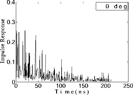
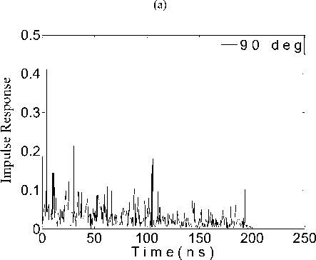
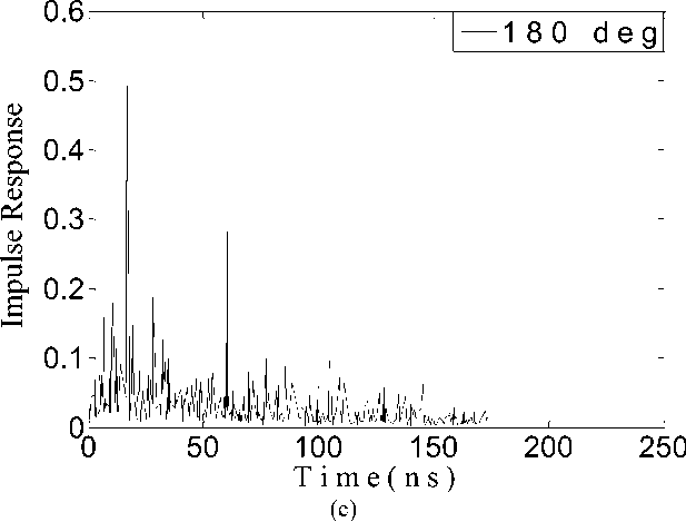
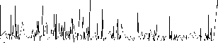
From the description of the model given in the previous section, the extensive simulation has been carried out to generate the power delay profile of the body surface to external nodes communicating in body area network. Fig. 1 shows the delaying of the received signal power as a function of the time, giving an intuitive inspection of the multipath channel transmission. The degradation of the signal with time as it travels over the channel is minimum in case of 0-degree body direction as shown in Fig. 1., because with increasing angle of body direction the effect of shadowing by body is dominating. So the signal from the antenna which is totally aligned with the transmitting antenna i.e. with 0-degree body direction is more preferred as compared to non-aligned antenna i.e. 90, 180 and 270-degree direction.
(b)
UWB СМ4 for WBAN for 90-deg
(b)
д
Дн
О
3 р. е
00 50 100
T i m e ( n s ) (d)
,^ЗАз1Н\и1у^у^______
UWB CM4 for WBAN for 180-deg
(c)
Fig.1. Impulse Response of Channel Model CM4 for a) 00; b) 900; c) 1800; d) 2700 Body Direction
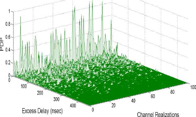
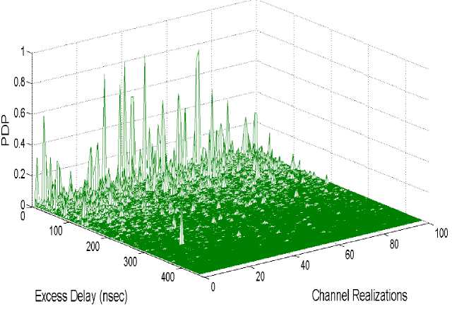
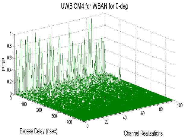
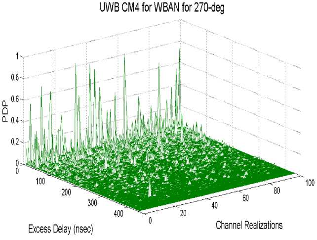
The PDP have generated through simulation for four different body directions with average over 100 local PDPs for each path as shown in Fig. 2. The results shows that minimum mean power delay is there in case of 0-degree body direction when the transmitting antenna is aligned in direct line with the receiving antenna, as presented in Table 2.
(a)
(d)
Fig.2. PDP of Channel Model CM4 for a) 00; b) 900; c) 1800; d) 2700 Body Direction
Table 2. Mean Power Delay of Channel Model CM4 for Different Body Direction
|
Body direction |
Mean Power delay |
|
00 |
0.0214 |
|
900 |
0.0235 |
|
1800 |
0.0266 |
|
2700 |
0.0281 |
-
A. Statistical Channel Attributes
The delay spread is an important parameter to compare the different multipath channels by measuring the multipath density within the channel. The mean delay spread and RMS delay spread are two multipath channel parameters that can be obtained from the power delay profile of the channel. The mean delay spread is the average delay spread weighted by power and RMS delay spread is the energy-weighted standard deviation of the signal delays [9].
∑ =∑ ^
∑ jttj =∑ jpj
TRMS = √∑ - ^m (5)
Where a j is the amplitude of the received signal and τm is the delay related to the first detected signal at the receiver [10].
The mean delay (τm) and RMS delay (τRMS) have been computed for different body directions to plot the complementary CDFs, as shown in Fig. 3 and 4. The sharp decline of CDF curves in case of 0-body directions shows less fading, as the transmitting antenna is directly facing the receiving antenna so there are fewer interacting objects. The channel with 00 body direction shows minimum mean (28.4 ns) and RMS (35 ns) delay spread while these values are maximum for 2700 body direction as presented in Table 3.
So the growing angle of body direction shows negative effects on channel characteristics of WBAN.
Table 3. RMS and Mean Delay Spread of CM4 for Different Body Direction
|
Body Direction |
RMS delay spread (ns) |
Mean delay spread (ns) |
|
00 |
35 |
28.4 |
|
900 |
41 |
36 |
|
1800 |
42.1 |
41.6 |
|
2700 |
49.8 |
54.2 |
-
B. Discrete Realization of PDF and CDF
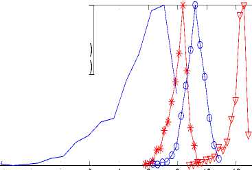
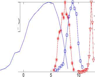
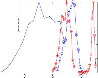
The system performance is evaluated by the probability density function (PDF) and cumulative distribution function (CDF) of the received SNR. The output SNR is obtained by adding the SNR of the selected bins corresponding to each realization of PDP. The discrete realization of output SNR’s PDF and CDF for different body direction with UWB is shown in Fig. 5 and 6. The channel profiles have been generated for normalized channel energy while the average SNR is set to 70 dB. Even the S-Rake and P-Rake receivers with 2 and 16 taps are considered to obtain the results for CM4 channel conditions.
The diversity gain performance gap between S-Rake and P-Rake widens to 4.1 dB in 270-degree body directions as compares to 2.6 dB in 0-degree body direction with 2 finger structure as shown in Fig. 5. The weaker multipath component in 270-degree direction, due to strong shadowing effects of the body is the reason of this degraded performance. This shows the poor effect of increasing body direction angle on the performance of channel model CM4 of body area network.
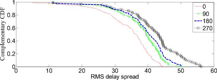
Fig.3. Cumulative CDF of RMS Delay Spread of CM4 for Different Body Directions
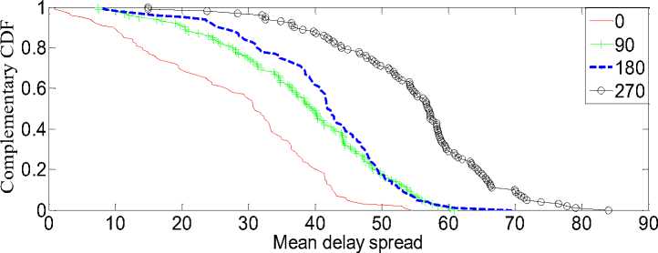
Fig.4. Cumulative CDF of Mean Delay Spread of CM4 for Different Body Directions
0.8
LL 0.6
Q
+S
-P
VS
■е P
1 0.4
0.2
P D F o f re c e i ve r o u t p u t S N R i n C M 4 fo r 0 - d e g re e
R a k e ( 2 T a p s)
R a k e ( 2 T a p s)
R a k e ( 1 6 T a p s)
R a k e ( 1 6 T a p s)
0-6 -4 -2 0 2
0.8
IL 0.6
Q
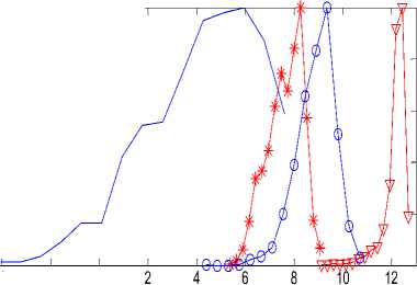
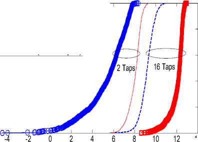
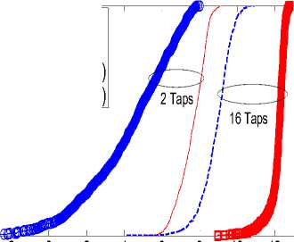
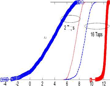
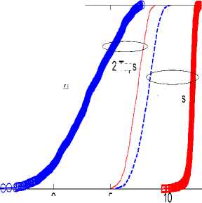
Fig. 6 shows the CDF of the output SNR for the S-Rake and P-Rake structure for different body directions of body area network. The slope of CDF in S-Rake and P-Rake is quite different, which is attributes to fading i.e. relative difference in amplitude of multipath delay bins. The slope of the CDF depends upon the shadowing effect caused by the human body in body area networks. This cause the average received SNR in 270-degree body direction reduced compares to other body directions. The almost steep slope obtained with S-Rake structure as compares to P-Rake structure affirms their improved performance. Example, the average SNR obtained with 2-taps structure is 2.6 dB more in case of S-Rake as compared to P-Rake. The average received SNR has been observed to be diminished in 2-taps receiver structure compared to 16-taps receiver structure scenario because of absence of strong MPC in the first few bins. The improved performance of 16 finger partial structure compares to 2 finger selective structure explains that the performance of best two multipath components is far poorer than the first 16 multipath components. Alternatively, the energy captured by the 16 finger partial structure is much more than the 2 finger selective structure.
O u t p u t S N R ( d B ) (a)
P D F of re ce i ve r o u t p u t S N R i n C M 4 fo r 9 0 - d eg re e
0.2
0-6 -4 -2 0
O u t p u t S N R ( d B )
(b)
♦S R a k e ( 2 T a p s )
P R a k e ( 2 T a p s )
V S R a ke ( 1 6 T a p s )
-e- P R a k e ( 1 6 T a p s )
й- 0.4
0.8
*S R a k e ( 2 T a p s)
P R a k e ( 2 T a p s)
vS R a k e ( 1 6 T a p s)
ш 0.6 -e- P R a k e (1 6 T a p s )
Q
1 0.4
0.2
-5
P D F o f re c e i v e r o u t p u t S N R i n C M 4 fo r 1 8 0 - d e g r e e
O u t p u t S N R ( d B )
(c)
0.6
□
0.8
0.6
+S
P
VS
-O- P
Q d
0.4
0.2
■fl- S ... P
S
C DF of receiver output S NR in CM 4 for 0-degree 1
0.4
0.2
0-6
O u t p u t S N R ( d B ) (a)
R a k e ( 2 T a p s)
R a k e ( 2 T a p s)
R a k e ( 1 6 T a p s)
R a k e ( 1 6 T a p s)
C DF o f re c e iv e r o u t p u t S NR in CM 4 fo r 9 0 - d e g re e 1
0.8
O u t p u t S N R ( d B )
(b)
R a k e ( 2 T a p s)
R a k e ( 2 T a p s)
R a k e ( 1 6 T a p s)
R a k e ( 1 6 T a p s)
S
-e- P
■» S
P
P D F o f re c e i ve r o u t p u t S N R i n C M 4 fo r 2 7 0 - d e g re e
O u t p u t S N R ( d B ) (d)
R a k e ( 2 T a p s )
R a k e (2 T a p s )
R ak e ( 1 6 T a p s )
R a k e( 1 6 T a p s )
0.6
0.4
0.2
0-6
м»
-4
-5
Fig.5. PDF of Rake Receivers SNR Distribution in CM4 for a) 00; b) 900; c) 1800; d) 2700 Body Directions
CDF of receiver output SNR in CM4 for 1 80-degree 1
2 Taps
R a k e ( 2 T ap s )
R a k e ( 2 T ap s )
R a k e ( 1 6 T a p s)
R a k e ( 1 6 T a p s)
0.8
L 0.6
Q
° 0.4
0.2
0-6
S
-е- P
-в- S
P
O u t p u t S N R ( d B )
(c)
C DF o f re c e iv e r o u t p u t S NR in CM 4 fo r 2 7 0 - d e g r e e
2 Taps
0.8
L 0.6
S
-е- P
*S
P
о
0.4
0.2
R a k e ( 2 T a p s)
R a k e ( 2 T a p s)
R a k e ( 1 6 T a p s)
R a k e ( 1 6 T a p s)
16 Taps
№
-5 05
O u t p u t S N R ( d B )
(d)
Fig.6. CDF of Rake Receivers SNR Distribution in CM4 for a) 00; b) 900; c) 1800; d) 2700 Body Directions
So using the 0-degree body direction communication with 16-taps partial rake structure can provide the desirable performance of the channel model CM4 in body area network with the reduced hardware complexity.
-
V. Conclusions
Acknowledgment
We owe our debt of gratitude to our department for the vision and foresight which inspired us to conceive this work. We thank almighty, our parents and teachers for their encouragement without which this project would not be possible.
References On Statistical Behavioral Investigations of Body Movements of Human Body Area Channel
- Sukhraj Kaur, Rachita Sharma and Jyoteesh Malhotra, "Simulative Investigations of Wireless Body Area Network through Varied Channel Conditions", International Journal of Computer Applications (0975 – 8887), Volume 74– No.7, July 2013.
- Zimmerman, T. G., "Personal area networks: near-field intrabody communication", IBM Systems Journal, 35(3.4), pp. 609–617, 1996. doi: 10.1147//sj.353.0609.
- Yazdandoost, K. Y., & Sayrafian, P. K., "Channel Model for Body Area Network (BAN)", IEEE802.15.6 technical contribution, 2009. doc.: IEEE P802.15-08-0780-09-0006.
- Proakis, J. G., Digital Communications (4th edition). New York: McGraw-Hill, 2001.
- Qui, R. C., Lui, H., & Shen, X. (S.), "Ultra-wideband for multiple-access communications", IEEE Communication Magzine, vol. 43, pp. 80-87, 2005.
- M. Sudjai, L. Chung. Tran & F. Safaei, "Performance analysis of STFC MB-OFDM UWB in WBAN channels", 23rd IEEE International Symposium Personal, Indoor and Mobile Radio Communications (PIMRC 2012), pp. 1710-1715, 2012. doi: 10.1109/PIMRC.2012.6362625.
- Wang, J., & Wang, Q., Body area communications- Channel Modeling, Communications and EMC, 2013 edition. Singapore: Wiley, IEEE Press.
- Dr. Jyoteesh Malhotra, "Error Rate Performance in High Data Rate UWB Channels for Wireless Personal Area Networks", International Journal of Computer Applications, vol.10, no.6, pp. 31–37, 2010.
- JJW Siemons, Measurement Based Indoor Radio Channel Model (Koninklijke Philips Electronics, 2000).
- Lingli Xia, Stephen Redfield and Patrick Chiang, "Experimental Characterization of a UWB Channel for Body Area Networks", EURASIP Journal on Wireless Communications and Networking, 2011. doi:10.1155/2011/703239.
- Lu Shi, Ming Li, Shucheng Yu and Jiawei Yuan, "BANA-Body area network authentication exploiting channel characteristics".
- Jyoteesh Malhotra, "Simulative Investigations on Low Data Rate IEEE 802.15.4a UWB Channel for Wireless Personal Area Networks", International Journal of Information and Telecommunication Technology (IJITT), Vol. 2, No. 1, pp. 57-65, 2010.
- Miniutti, D., Hanlen, L., Smith, D., Zhang, A., Lewis, D., Rodda, D., & Gilbert, B. (2008), "Narrowband On-Body to Off-Body Channel Characterization for Body Area Networks", IEEE802.15.6 technical contribution. doc.: IEEE P802.15-08-0559-00-0006.
- Win, M. Z., & Scholtz, R. A., "On the robustness of ultra -wide bandwidth signals in dense multipath environments", IEEE Communication Letter, vol. 2, 51–53, February, 1998. doi: 10.1109/4234.660801.
