On the Role of Overlapping Factor in FBMC-SMT Systems

Author: Saurabh Srivastava, O.P. Sahu
Journal: International Journal of Image, Graphics and Signal Processing(IJIGSP) @ijigsp
Article in issue: 3 vol.7, 2015.
Free access
The overlapping factor has a vital role in determining the optimum bandwidth utilization and the desired side band suppression. In this paper, we review one of the filter bank multicarrier technique-staggered multi tone modulation, discuss its efficient implementation in polyphase form and compare between several performance parameters of the same. We also discuss the role of overlapping factor in staggered multi tone modulation systems. We describe a low complexity procedure for generation of the required overlapping factors based on frequency sampling method. Our simulations describe the effectiveness of the optimum value selection for overlapping factor in a staggered multi tone modulation system. The proposed system is theoretically found to be compatible with the Long Term Evolution standards. The performance evaluation of the proposed system in ideal conditions emphasizes about the reduction in spectrum leakage in sidebands of the staggered multi tone modulation system, along with a little increase in system complexity.
Filter Bank Multi Carrier, spectrum leakage, overlapping factor, complexity, polyphase representation, latency, bandwidth efficiency
Short address: https://sciup.org/15013535
IDR: 15013535
Text of the scientific article On the Role of Overlapping Factor in FBMC-SMT Systems
Recently lot of work has been reported on multicarrier communications. This communication utilizes the large spectrum of wideband signals by dividing the frequency spectrum among narrow bins called subcarriers or tones. Information is transmitted using these subcarriers. For the sake of proper recovery of the transmitted data, these multiple tones are preferred to be orthogonal. The closeness of multicarrier communication with Orthogonal Frequency Division Multiplexing (OFDM) is studied in [1, 2, 3]. OFDM has emerged as a key multicarrier modulation scheme in digital communication systems. Due to some of the limitations such as PAPR and spectral leakage in neighboring sidebands, some modifications in OFDM were suggested that led to the development of
Filter Bank Multi Carrier (FBMC)-Filtered Multi Tone (FMT), Cosine Modulated Multi Tone (CMT) and Staggered Multi Tone (SMT) systems. These are a few choices for FBMC. FBMC finds extensive use in multirate filtering as mentioned in [16]. The emphasis of this paper is on a type of FBMC that has been widely studied in the literature and often referred to as OFDM/OQAM where OQAM stands for offset quadrature amplitude modulation [4]. The word offset reflects the fact that, in OQAM, the in-phase and quadrature components of each data symbol have a timeoffset of half a symbol interval. In [4] it has been mentioned that the term staggered QAM has also been used to refer to OQAM and accordingly it has been called as Staggered Multi Tone (SMT). In this paper, we consider SMT for implementation of FBMC systems.
It was suggested in [5] that filter banks may be used for modulation and as a spectrum sensing device. This has also been stated as the right candidate for cognitive radios [5]. The application of filter banks for spectrum sensing has been studied in [5]; however the performance of filter bank SMT systems depends upon the overlapping factor but has not been studied in any of the reported literatures. This paper suggests a low complexity method for generation of optimum overlapping factor for usage in FBMC-SMT systems. The performance of the SMT system is studied regarding the bandwidth expansion, complexity and side band suppression in the FBMC-SMT system. Our extensive simulations verify the effectiveness of the determined overlapping factor in FBMC communications.
This paper is arranged as follows: Section I gives the basics of filter bank system and its reported applications in digital communication systems. Section II gives the idea of FBMC-SMT systems and the overlapping factor in FBMC systems. Section III describes the polyphase efficient structure of the SMT system, section IV gives the performance evaluations of the proposed system with various overlapping factors. Section V presents the simulation results and finally Section VI summarizes the contribution of the paper with results and discussion.
II. Background
s i = _ s 0, i
s 1, l
SM - 1, l
T
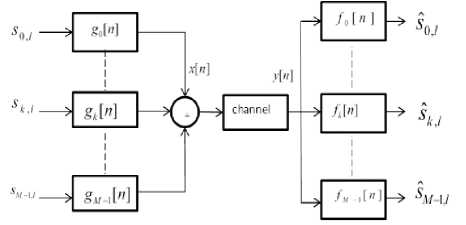
Fig. 1. Block diagram for a general FBMC system
The corresponding output signal vector from the transmitter as xl =[x[(l -1)L] x[(l -1)L + 1] ...... x[lL -1]f (5)
The corresponding received signal vector at the receiver as:
y l = [ y [( l - 1) L ] y [( l - 1) L + 1] ...... y [ lL - 1] ] r (6)
A general filter bank multicarrier transmitter and receiver section is shown in Fig. 1. The complex input x [ n ] consists of a given set of symbols spread over given number of tones (multi-carriers), and then processed through a given set of synthesis filter. The transmitted signal passing through the noisy channel is then processed by a given set of analysis filters to provide an estimate of the given symbol in a specific carrier. The analysis and synthesis filters, commonly called as a filter bank, are related mathematically so as to minimize the effects of the channel.
As shown in Fig. 1, the transmitted signal x [ n ] can be expressed as:
M - 1
4 n ] = EE s k , i g k [ n - L ] (1)
l k = 0
where m is the number of subcarriers, s is the lth symbol in the kth subcarrier, L is the number of samples per transmit symbol spacing, and g [n] is the synthesis filter for the kth subcarrier. At the receiver, the estimated lth symbol sˆ in the kth subcarrier is sk,l = (y[n] * fk[n])n = lLs (2)
where y [ n ] is the received signal and f [ n ] is the impulse response of the analysis filters for the k th subcarrier. In OFDM, the input symbols s are QAM symbols and Ls = L , where L is the number of samples per symbol duration, and L > M . For an ideal channel with y [ n ] = x [ n ] , a QAM symbol sk , equals sk z, if the filter satisfies orthogonal condition:
(gk [ n - mLs ] , f [ n - lL ]) = S ki S mi (3)
Where S b is the Kronecker delta function. Defining the l th input symbol vector along all subcarriers as
and the estimated l th symbol vector as
~ Г л
S l = _ s 0, l
^
s ˆ1, l
SM - 1, l
The synthesis and analysis filters are defined in [6] as:
g k [ n ] = f k [ n ] = p[ n ] W kn (8)
where j w kn = e - j2 n / L . The prototype filter p[n ] = 1/ V L for n=0, 1, 2^.L-1 and zero elsewhere. Substituting (8) into (1), the transmitted signal for the l th symbol is obtained as:
x l = ^Д^ F L [ I M 0 M x( L - M )] Г s l
Where the (i,j)th element of the LxL DFT matrix F is
( PL)tj. = W(i - 1X- j - 1) i ,. j = 1,2... L . (10)
and the IDFT matrix is given by: F H / L . Similarly the estimated l th symbol is obtained as:
•^ l = ,j£[ I M 0 M x ( L - M )] F L y l (11)
The OFDM transmitter can be implemented by using zero padding, IFFT and P/S conversion. The OFDM receiver can be implemented by using S/P conversion and FFT.
In OFDM-OQAM or SMT, the input symbols s are
OQAM symbols and L = L / 2 , where L is the number of samples per symbol duration, and L > M . The OQAM symbols are defined as:
5 = ik+lsR sk,l j sk,l ’
where s R is the real input sequence
sR =Я{j—k+1) sk, 1} and the l’th input QAM symbol sˆ is given as:
RR sk 1 - = s + js(15)
k,1 k ,21' J k ,21 '+1
The analysis and synthesis filters are given as:
gk [ n ]=fk [ n ]=p[ nWWT(16)
where b = ( L — 1) / 2 , and the length Lp prototype filter p [ n ] is a square root Nyquist filter with roll off not greater than 1.
-
A. FBMC-SMT System and Overlapping Factor
In this paper we use the frequency sampling based prototype filters [6, 7] for our simulation. Using this method, we first determine the L desired values of H ( k / L ),0 < k < L — 1 in the frequency domain as H (0) = 1, H (1/ L ) = 0.971960 H (2 / L ) = sqrt (2) / 2, ,
H (3/ L ) = 0.235147and H ( k / L ) = 0,4 < k < L — 1 .
These particular values are chosen in accordance with the spectral response of the desired prototype filter. We assume the prototype filter length l = kl — । , where the integer K is the overlapping factor (the number of symbol durations in the prototype filter length. The synthesis and analysis filters can be implemented in efficient polyphase form as given in section III. Prototype filters are characterized by the overlapping factor K, which is the ratio of the filter impulse response duration to the multicarrier symbol period T. The factor K is also the number of multicarrier symbols which overlap in the time domain. Generally, K is an integer number and, in the frequency domain, it is the number of frequency coefficients which are introduced between the FFT filter coefficients [8], [9]. K also determines the achievable stop band attenuation [10].
A large value of K represents long filter impulse response duration than the multicarrier symbol period.
This means the filter response extends to various symbols. This also requires a large number of frequency coefficients that increases the system complexity at the expense of filter bank’s attenuation characteristics. On the other hand, a small value of K represents less complex system, but a poor filter attenuation response. Hence it justifies the requirement of proper selection of the overlapping factor for optimum tradeoff between attenuation characteristics of the filter bank and its complexity requirements.
-
III. E fficient I mplementation O f F bmc -S mt
Efficient polyphase implementations of FBMC-SMT for synthesis filter bank (SFB) and analysis filter bank (AFB) have been investigated in the literature. To make a system operable using with either OFDM or FBMC-SMT, the IFFT-based SFB and FFT-based AFB should be chosen.
-
A. Synthesis filter bank:
The Z-transform’s of the synthesis filters are:
Gk ( z ) = W k [1 W — k ..... W — k ( L — 1) ] A ( z L ) c ( z ) (17)
where
A ( z L ) = diag { A o ( z L ) A 1 ( z L ) ..... A l _ , ( z L )} (18)
c ( z ) = |^ 1 z —1 z — L J (19)
The polyphase filters in (18) are defined as:
A ( z ) = ^ p [ q + mL ] z — m q = 0,1,...., L — 1 (20)
m
Defining the Z transform of the input symbols s as S ( z ) , and the Z transform of x [ n ] as
L
X ( z ) = c T ( . -) A (?) F H Л , ь [ I M 0 M , ,L — M , ] S ( -■ !) (21)
Where
A , b = diag {1 WbL ...... W LL — ') b } (22)
Then X ( z ) can be rewritten as:
L
X(z ) = c T ( z ){ A 2 P , b F £ " [ I M 0 „ , ( l — „ ) ] S }( z =)(23)
Where
A 2 ( z ) = A ( z 2) (24)
and the matrix P (Permutation matrix) is given by:
P n b L - b ) OI b ! = 1 F H Л п ь F l (25)
_ I L - b 0 ( L - b ) x b J L
Based on (23), the FBMC-SMT SFB can be implemented by using zero padding, IFFT, permutation matrix P , polyphase filters A ( z 2) , and P/S conversion. The polyphase structure is as shown in Fig. 2.
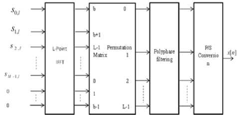
Fig. 2. Polyphase FBMC-SMT SFB
-
B. Analysis Filter Bank:
Defining the Z transform of the received signal y [ n ] as Y [ z ] and that of estimated symbols s ˆ as S ( z ) . Since the analysis filters are same as the synthesis filters, in an AWGN channel, the IFFT based AFB could be written as:
LL
S ( z 2 ) = {[ I M 0 M x ( L - M ) ] F H P ^ A 2 }( z 2) c ( z ) Y ( z ) (26)
The permutation matrix P relates the DFT and IDFT matrix as:
filters A ( z 2 ) , permutation matrix P , FFT and discarding irrelevant outputs. Its polyphase structure is given in Fig. 3.
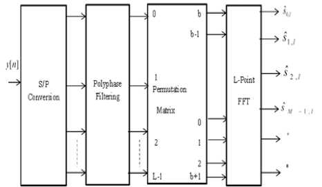
Fig. 3. Polyphase OFDM-SMT AFB
Note that the inputs to the SFB (resp. the outputs from the AFB) are purely real or imaginary, and so, a L/2-point cosine modulated filter bank and a L/2-point sine modulated filter bank could be used to replace the IFFT at the SFB (resp. the FFT at the AFB), as in the critically sampled exponentially modulated filter bank.
As such, the AFB’s complexity could be reduced almost by half. However, if the system design strategy is to make it operable using either OFDM or FBMC-SMT, the IFFT-based SFB and FFT-based AFB structure should be chosen.
IV. Comparison Of Bandwidth Efficiency, Computational Complexity And Latency
-
A. Bandwidth Efficiency
10..0
0..01
0.010
Defining the total time spacing for transmitting one QAM symbol ( 2 PAM symbols) as T QAM , and the total frequency spacing for transmitting one QAM symbol as F QAM . The bandwidth efficiency [11] is defined as:
P , o
F LH F L
Y =-------
QAM QAM
Substituting (27) into (26),
LL
S ( z 2) = {[ I M 0 M x (L - M ) ] F l P n c A 2 }( z 2) c ( z ) Y ( z ) (28)
where the permutation matrix
P = P P T, nc na nb
Based on (28), the FFT-Based FBMC-SMT AFB can be implemented by using S/P conversion, polyphase
Denoting one symbol duration as T, and assuming OFDM with CP, F QAM as subcarrier spacing 1/T, and T QAM = T + T CP where T CP is the CP duration.
In FBMC-SMT, F QAM is subcarrier spacing 1/T, and T QAM = T (symbol duration). Hence, OFDM with CP is less bandwidth efficient than FBMC-SMT.
-
B. Computational Complexity
The complexity is described for critically sampled case (M=L). For OFDM, the number of real multiplications of an L-point FFT/IFFT with L complex inputs is given as: nmu / = L log2 L - 3 L + 4 . Hence, the total number of real multiplications of OFDM per M QAM symbols is c OFDM = 2 n mul = 2 L log 2 L - 6 L + 8 .
For FBMC-SMT, the number of real multiplications of an L-point IFFT with L purely real or imaginary inputs is cRг = L log^ L — з L + 4. Therefore, the total number of real multiplications of FBMC-SMT per M QAM symbols (2M PAM symbols) is cFBMC—SMT 2(cFFT + 2Lp ) + 2(cFFT + 2Lp )
= 3 L log2 L + (8 K - 10) L + 24
Table 1. Complexity Comparison of OFDM and FBMC-SMT System
|
L |
c OFDM |
c FBMC — SMT ( Lp = KL + 1 ) |
||
|
K=3 |
K=4 |
K=5 |
||
|
128 |
1032 |
4504 |
5528 |
6552 |
|
512 |
6152 |
21016 |
25112 |
29208 |
|
2048 |
32776 |
96280 |
112664 |
129048 |
-
C. Latency
Let the sample duration be T = T / L . In OFDM, latency arises due to S/P and P/S conversion and CP. The latency due to an L: 1 P/S and 1:L S/P conversion pair is LT = T . Hence, the total latency for OFDM is:
-
T OFDM 1 + CPP .
In FBMC-SMT, latency due to the prototype filter is ( L — 1) T = KT . Latency also comes from OQAM modulation (T/2), P/S and S/P conversion pair, and filtering. The total latency is: Tfbmc — SMT = - + T + KT = ( K + 1.5) T
Table 2. Latency in OFDM system
|
T CP |
0 |
5.2μs |
4.7 μs |
16.7 μs |
|
T OFDM |
0.0667ms |
0.0719 ms |
0.0714 ms |
0.0834 ms |
Table 3. Latency in FBMC-SMT System
|
K |
3 |
4 |
5 |
|
T FBMC — SMT |
0.3000 ms |
0.3667 ms |
0.4334 ms |
V. Simulation results
Fig. 4 shows the magnitude response of prototype filter in OFDM and FBMC-SMT system. Note the sharp transition from main lobe to first adjacent lobe in the FBMC-SMT system.
Within a normalized frequency of 0.2 n radians/sample, the magnitude characteristics of FBMC-SMT shows more than 60 dB attenuation, that increases to about 85 dB attenuation at 0.5 n radians/sample. Fig. 5 shows the magnitude response of prototype filters for various values of K in an FBMC-SMT system.
The decay in FBMC-SMT system is much more than the OFDM system. This verifies that the adjacent side band attenuation between main lobe and first side lobe in FBMC-SMT systems is more than twice of corresponding OFDM system.
VI. Discussion And Conclusion
As seen from Fig. 4 and Fig. 6, rapid decay is observed across sidebands or sub channels in the frequency response of the SMT system for both values of K, which is much larger than for OFDM system. This suggests large sub channel isolation in FBMC-SMT systems.
From Fig. 5, it is found that the optimum value of overlapping factor in terms of sideband suppression is K=4. The difference between main lobe and first side lobe for K =4 is about 40 dB.
Fig. 7 shows the complexity is least in OFDM system, and complexity increases significantly while opting for SMT modulation. However, in SMT, if polyphase structure is adopted, this would lower the otherwise high complexity requirement of the system. Moreover, our simulations show that for OFDM transmit spectrum the difference is about 14 dB.
From the application point of view, our paper suggests the viability of using filter banks instead of the OFDM system in multicarrier systems. The formulations and the simulations in the paper suggest that using a moderate value of K =4, would provide sufficient side band spectral attenuation characteristics as desired by the MC systems, while keeping the system complexity low. The latency in FBMC-SMT system for a value of K=4 is found to be 0.3367 ms , which is 5 times that of latency in OFDM with a CP duration of 5.2 μs.
Although the high latency of FBMC-SMT system appears to be a disadvantage, but that is well versed with the round trip latency requirements of 5ms recommended by the LTE. Additionally, the FCC requirements of the sideband spectrum attenuation and the significant reduction in system complexity employing polyphase representation very well justify the application of FBMC-SMT system in wideband MC systems.
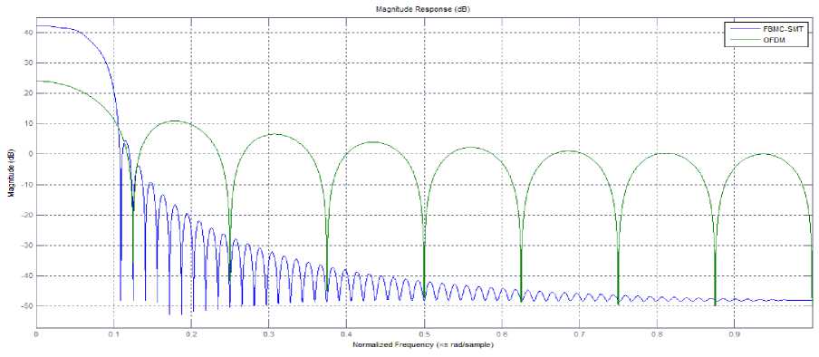
Fig. 4. OFDM and FBMC-SMT filter response for K=8.
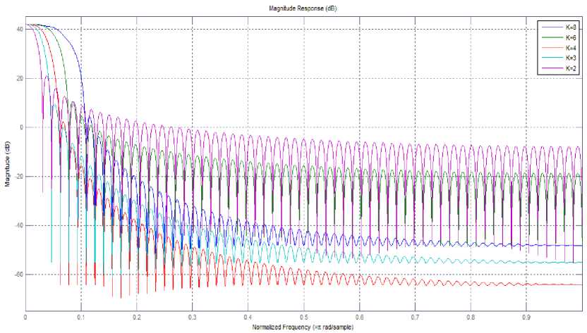
Fig. 5. Filter response for various values of K.
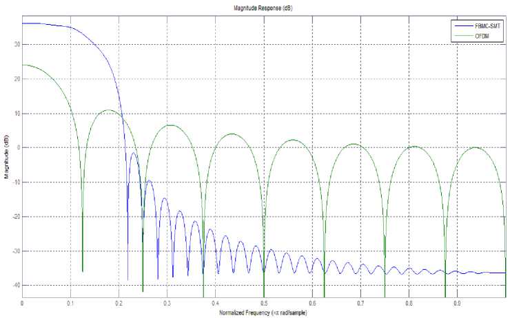
Fig. 6. OFDM and FBMC-SMT filter response for K=4.
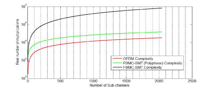
Fig. 7. Complexity comparison of OFDM, FBMC-SMT and FBMC-SMT (Polyphase) representations
References On the Role of Overlapping Factor in FBMC-SMT Systems
- Viholainen, M. Bellanger and M. Huchard, "Prototype filter and structure optimization", Physical Layer for Dynamic Spectrum Access and Cognitive Radio, Jan. 2009.
- George J. Miao, "Signal processing in digital communications", Artech House, 2007.
- P. Siohan, C. Siclet and N. Lacaille, "Analysis and design of OFDM/OQAM systems based on filter bank theory", IEEE Transactions on Signal Processing, vol.50, no.5, May 2002, pp.1170-1183, 2002.
- B. Farhang-Boroujeny and C. H. G. Yuen, "Cosine modulated and offset QAM filter bank multicarrier techniques: A continuous-time prospect", EURASIP Journal on Advances in Signal Processing, vol. 2010, Article ID 165654, 16 pages, DOI: 10.1155/2010/165654, 2010.
- B. Farhang-Boroujeny, "Tutorial: Filter Bank Multicarrier for Next Generation of Communication Systems", Wireless Symposium and Summer School at Virgina Tech, June 3, 2010.
- Ari Viholainen, Tero Ihalainen, Tobias Hidalgo Stitz, Markku Renfors, and Maurice Bellanger, "Prototype Filter Design for Filter Bank Based Multicarrier Transmission", 17th European signal processing conference, EUSIPCO, Glassgow, pp. 1359-1363, 2009.
- T. W. Parks and C. S. Burrus, Digital Filter Design. NY, USA: Wiley-Interscience, 1987.
- M. Bellanger, "FBMC Physical Layer: a primer" ,PHYDYAS, crowncom, pp. 1-31, 2010.
- A. Viholainen, M. Bellanger, M. Hutchard, report on Prototype filter and structure optimization, work package 5, phydyas doc. No. :PHYDYAS_ 007, pp. 1-102, 2009.
- Tero Ihalainen, Tobias Hidalgo Stitz, Ari Viholainen, and Markku Renfors, "Performance Comparison of LDPC-Coded FBMC and CP-OFDM in Beyond 3G Context", ISCAS 2006.
- Ahmad R.S. Bahai & Burton R. Saltzberg, Multicarrier Digital Communications: Theory and applications of OFDM, Kluwer Academic publishers, New York, 2002.
- L. Lin and B. Farhang-Boroujeny, "Cosine-modulated multitone for very-high-speed digital subscriber lines", EURASIP J. Applied Signal Processing, vol. 2006, Article ID 19329, 16 pages, 2006.
- M. G. Bellanger, "Specification and design of a prototype filter for filter bank based multicarrier transmission", Proc. IEEE Int. Conf. Acoustics, Speech, and Signal Processing, Salt Lake City, USA, May 2001, pp. 2417–2420, 2001.
- T. Saram?ki and R. Bregovi, "Multirate Systems: Design and Applications", Idea Group Publishing.
- A. Viholainen, J. Alhava, and M. Renfors, "Efficient implementation of complex modulated filter banks using cosine and sine modulated filter banks", EURASIP Journal on Advances in Signal Processing, vol. 2006, Article ID 58564, 10 pages, DOI: 10.1155/ASP/2006/58564, 2006.
- Ogale Jyotsna v. ,Jain Alok, "Cosine Modulated Non-Uniform Filter Bank with Improved Computational Efficiency", IJIGSP, Vol. 4, No.2 , pp.1-8, 2012.
