Operator Design Methodology and Application in H.264 Entropy Coding

Author: Ziyi Hu, Teng Wang, Kuilin Chen, Zheng Xie, Xin'an Wang
Journal: International Journal of Information Engineering and Electronic Business(IJIEEB) @ijieeb
Article in issue: 1 vol.2, 2010.
Free access
Currently ASIC applications, such as multimedia processing, require shorter time-to-market and lower cost of Non Recurring Engineering (NRE). Also, with the IC manufacturing technology developing continually, from transistor level to logic gate level, the size of design cells in digital circuits is increasing correspondingly. New design methodology is in urgent need to meet the requirement for the developing processing technology and shorter time-to-market in IC industry. This paper proposed the concepts and principles of operator design methodology, then focused on the entropy coding application based on the operators and finally presented the implementation results. The results show that with the proposed methodology, a comparable hardware performance can be obtained against the traditional standard cell based design flow. Furthermore, the design speed can be improved efficiently.
Operator design methodology, rapid design, H264, entropy coding
Short address: https://sciup.org/15013048
IDR: 15013048
Text of the scientific article Operator Design Methodology and Application in H.264 Entropy Coding
Published Online November 2010 in MECS
The processing technology of IC (integrated circuit) has been increasingly improved according to the Moore’s Law, and the average annual growth rate can approach 58%, but the annual growth rate of design efficiency is about 20%~21%[1]. The efficiency of IC design is seriously lagging behind the progress of manufacturing process. On the other hand, Non-Recurring-Engineering (NRE) and time-to-market have taken a more important role on IC design, and the traditional IC design, taking unbearable time with engineers’ personal intelligence and unique understanding, is difficult to satisfy this requirement.
Aiming at speeding up the IC design, novel methodologies are proposed constantly by worldwide researchers. One of the most significant technologies is High-Level Synthesis (HLS), which can speed up IC design largely based on target cells with various granularities. In this area, there are several commercial tools delivered in the last few decades. These tools cover several market segments from the traditional behavioral synthesis [2] (e.g. Mentor’s Catapult, Forte, Synfora, etc) to new applications such as FPGA-based coprocessor design[3] (e.g. Impulse CoDeveloper or Altera’s C2H) and synthesis of DSP algorithms (e.g. Mathworks’s MATLAB). However, HLS has not been widely accepted in the engineering practice, which is primarily due to the quality loss against artificial designs and the various limits on using HLS[4].
To verify the practicability of operator design methodology, entropy coding for H.264/AVC video encoder is implemented, which is widely used in multimedia applications. The results can fully prove that the proposed methodology has advantage of accelerating IC design and has comparable performance with other IC designs.
-
II. P RINCIPLE OF O PERATOR D ESIGN M ETHODOLOGY
The most important problem that an operator methodology will solve is how to shorten the time-to-market in a quickly changeable environment and obtain comparable performance with traditional IC methods. There are two main factors that influence the design speed. Firstly, custom standard cells are too fine-grained and coarse-grained design cells are in need, just like building a skyscraper only by bricks. In contrast, slab of stone and an existing and complete set of components can do great help to this work. Secondly, IC design engineer used to spend too much time on understanding the algorithms that was to be implemented, and translating them into RTL description manually. Hence, operator methodology will define a special cell named operator and develop a set of auto translate mechanism. Design engineers only need to have a rough understanding of the algorithm and do some timing analysis and annotating, and then mapping and optimization work will be done by compiler and optimizer automatically or by engineers more easily.
-
A. Completeness of Operator Methodology[7]
Four types of operator are proposed: Controlling Operator, Algebra Operator, Storage Operator and Link Operator. Integrated circuits are composed of a set of controlling logic units and processing logic units. The former is used to deliver configure instruction, and the later which is composed of algebra operator, storage operator and link operator executes the task according the instruction settled. The controlling operators give configurable instructions to the algebra operators for processing tasks. Algebra operator performs an operation on the input data. Storage operator performs data storage and readout. Link operator performs as data input and output paths of the channel selection. The circuit based on operator is any one of or any combination of algebra operator, storage operator, link operator and even controlling operator. The four categories of operators are complete and they can achieve any form of IC circuit design.
-
B. Structure of Operator
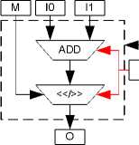
Algebra operator is composed of operation configuration register and algebra logic operation cell. The operation configuration register receives and stores the operation configuration dictates from the controlling operator. The algebra logic function of algebra operator consists of but is not limited by basic arithmetic and logic operation (such as addition, minus, multiply, divide, accumulation addition, bit shift, comparison, fetching high, fetching low and so on). The reconfiguration function of algebra operator also includes algebra proper operation (such as fetching absolute value after dividing, average, filter operation for proper coefficient and so on). As a example, ADDS operator can carry out the operation of addition and bit shift according to different configuration information. The structure is shown in Figure 1. It can accelerate greatly the executable capability of video compression arithmetic. Algebra operator deals with the input data directly and gives the output result.
input datas

algebra logic
operation cell configuration register
-^-------output datas
Figure 1. The structure of ADDS algebra operator
Storage operator includes storage configuration register and a storage cell. It can configure the readin and/or read-out of the storage operator memorizer (various storage mediums: register, MEM such as RAM and so on) and the working mode of the address generator which the storage corresponds to by the configuration register. According to the address generated by the address generator, MU stores directly the input data in scheduled location, and outputs the data in need from the storage location. The general structure of storage operator is shown in Figure 2.
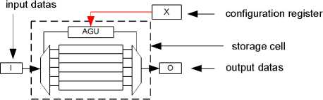
Figure 2. The general structure of storage operator
Link operator includes a router configuration register and a router selection cell. The links between input data and output data can be setup by the configuration register. Link operator contains a set of data registers and switches. Data registers are used to store temporary input and output data of algebra operators and storage operators. Link operator are controlled by controlling operator, to setup links between different operators. Its general structure is shown in Figure 3.
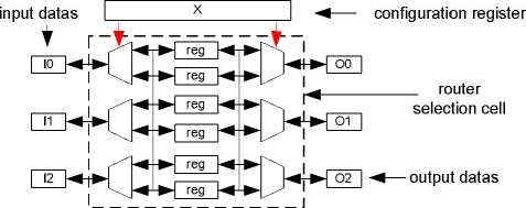
Figure 3. The general structure of link operator
Controlling operator is used to deliver configuration information to relevant configuration registers, choose certain functions of algebra operators, storage operators or link operators, in order to implement the corresponding algorithm. There are three type of CU, including counter, FSM(finite state machine) and microinstructions. Figure 4 illustrates the structure of FSM controlling operator.

Figure 4. The structure of FSM controlling operator
-
C. Operator Methodology Process
A regular process based on operator methodology are proposed to conduct IC design, as shown in Figure 5. Compared with the similar flow which is proposed in [6], this process is more efficient. The key steps are illustrated as follows.
generate operator time marking structure graph
▼ operator library
aggregation verification and optimization finish: HDL output
-
Figure 5. Standard design flow of operator methodology
Key Step 1: Algorithm analysis. In this step, a sort of computer language, such as C programming language, is the input of the design flow. The task of this step is to analyze each segment of the high level language to obtain the information of input and output variables, functional calling relationship, and that of the subfunctions recursively.
Key Step 2: Generating operator structure graph. The task of this step is unfolding the whole algorithm into parallel hardware structure based on special operator design library, without considering any performance and advanced architecture like pipeline. The control and data flow graph (CDFG), which can illustrate the data dependences and hazards, is a helpful pattern to generate the operator structure graph.
Key Step 3: Aggregation and timing-marked. The task of this step is extracting timing information from data dependency and application requirement, as well as the constraint of the technology and frequency in operator design library. After that the timing information is drew into space-timing diagram.
Key Step 4: Verification and optimization. An autooptimization program will be employed to finish the step, from timing-modified space-timing diagram to the operator circuit and instruction code if necessary.
-
III. P RINCIPLE OF H.264 E NTROPY
-
A. Introduction to H.264
The Moving Picture Experts Group and the Video Coding Experts Group (MPEG and VCEG) have developed a new standard that promises to outperform the earlier MPEG-4 and H.263 standards, providing better compression of video images. The new standard is entitled Advanced Video Coding (AVC) and is published jointly as Part 10 of MPEG-4 and ITU-T Recommendation H.264[8]. With the wide breadth of applications considered by the two organizations, the application focus for the work was correspondingly broad – from video conferencing to entertainment (broadcasting over cable, satellite, terrestrial, cable modem, DSL etc.; storage on DVDs and hard disks; video on demand etc.) to streaming video, surveillance and military applications, and digital cinema[9]. Hence, it is meaningful to implement H.264 by the proposed design methodology.
In practice, a compliant H.264 encoder is likely to include the functional elements shown in Figure 6. The encoder includes two dataflow paths, a ‘forward’ path (left to right) and a ‘reconstruction’ path (right to left). With the exception of the deblocking filter, most of the basic functional elements (prediction, transform, quantization, entropy encoding) are present in previous standards (MPEG-1, MPEG-2, MPEG-4, H.261, H.263) but the important changes in H.264 occur in the details of each functional block.[10]
In H.264 video coding, one of the most functional elements is entropy coding, which is used to transform the range of the elements of video sequences into a symbol that is stored or transmitted as the compressed bit stream.
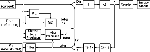
Figure 6. Top-level block diagram of H.264 encoder
-
B. Introduction to Entropy Coding
In H.264/AVC, there are two entropy coding modes. One is the context-based adaptive binary arithmetic coding (CABAC), which can be used to code all syntax elements in H.264/AVC. The other mode consists of two entropy coding tools: context-based adaptive variable length coding (CAVLC) and universal variable length coding (UVLC). Unlike CABAC, CAVLC is only used to encode quantized transformed coefficients (QTCs) while UVLC is adopted to encode header data, such as motion vectors (MVs), macro-block (MB) types, intra prediction type, and other flags.[11]
-
IV. H.264 E NTROPY E NCODER D ESIGN B ASED ON O PERATOR M ETHODOLOGY
Based on the theory of operator methodology, this paper has completed the implementation of IC hardware of H.264 entropy coding. The relationship between each function under the slice layer is shown in Figure 7 [12] [13].
I bs_write_ue (mb type );
х264_ macroblock _write_cavlc()
I4x4
I bs_write_ue h
I (i mode); ||
I bs_write_ue [I (ch mode);
I bs write se II | (4*4cbp);
.116x16
bs_write_ue
(mb typej 16*16);
bs_write_ue (ch mode);
P16x16
bs_write_se (qp);
bs_write_se (qp);
I bs_write_ue | (mb type);
I bs_write_se I]
| (mvd);
bs_write_ue (16*16cbp);
| bs_write_se h
Figure 7. Call relationship of function under the SLICE layer
In X264 code for entropy coding, we use the function bs_write_ue as an example to illustrate operator design process.
Bs_write_ue complete the unsigned Index of Columbus coding. Val is a parameter to be encoded, it is written to the structure bs_t from higher bits to low ones.
Table I is generated by parsing the function, which displays the relationship between signals of inputs and outputs for the function bs_write_ue.
Figure 8. The overall data flow structure of bs_write function
After the generation of CDFG, the next step is mapping the CDFG to the operator structure graph based on operator design library. The bs_write_ue function mainly uses algebra operators to achieve the structure, including ALU, shift-sub, sub-shift, and the corresponding operator structure are described as follows:
ALU algebra operator completes the irregular operations so that this sort of algebra operator is configurable and universal. Whereas, ALU algebra operator takes more resources, such as area, power, performance and so on. Hence, the scheduler will map the algorithm on to ALU only if necessary. The function and configuration coding is shown in Table II.
TABLE I. T HE I NPUT A ND O UTPUT S IGNALS O F B S _ WRITE _ UE FUNCTION
|
Signal |
Data type |
Directi on |
Description |
|
val |
uint32_t |
IN |
// Parameter values to be encoded |
|
i_size |
int |
IN |
//Identify the number of bits to write |
|
*s->p |
uint8_t |
IN |
// Register to be written |
|
p |
uint8_t * |
IN |
// The current bitstream position |
|
p_end |
uint8_t * |
IN |
// The end of bitstream position |
|
i_left |
int |
IN |
// Write a useful bit of target register |
|
*s->p |
uint8_t |
OUT |
// Register to be written |
|
p |
uint8_t * |
OUT |
// The end of bitstream position |
|
i_left |
int |
OUT |
// Write a useful bit of target register |
TABLE II. THE D ESCRIPTION OF ALU FUNCTIOIN
|
Function |
Coding X[15:0] |
Description |
|
ADD |
11100000_0000_0000 |
//Adder |
|
ADDC |
11101000_0000_0000 |
//Adder with carry |
|
SUB |
11110000_0000_0000 |
//Subtracter |
|
SUBC |
11111000_0000_0000 |
//Subtracter with carry |
|
ABS |
10110000_0000_0000 |
//Absolute value |
|
OPP |
10110100_0000_0000 |
//Opposite number |
|
MIN |
11110010_0000_0000 |
//Minimal value |
|
MAX |
11110001_0000_0000 |
//Maximal value |
|
SHLA |
01100000_1000_0000 |
//Shift arithmetical/logic left |
|
SHRA |
01100000_1110_0000 |
//Shift arithmetical right |
|
SHRL |
01100000_1100_0000 |
//Shift logic right |
|
ROT |
01100000_1001_0000 |
//Cycle shift |
|
AND |
01100000_ 0000_0001 |
//And |
|
OR |
01100000_ 0000_0010 |
//Or |
|
XOR |
01100000_ 0000_0100 |
//Exclusive-OR |
|
NOT |
01100000_ 0000_1000 |
//Not |
The operator function block of bs_write_ue can be generated according to X264 description after optimization on control and data flow graph, as shown in Figure 8. The operator block is the combination of the algebra operators, which is shown in three-dimensional block, storage operators, which is shown in rectangle, and link operators to link the operators together.
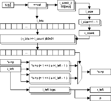
Figure 9 illustrates the structure of SUBS algebra operator, which is used to implement functions of subtraction and shift operations. Algebra operators are configurable and can be configured for a variety of algebra functions through the special kind of operator configuration bits, in which the control bits are used to choose a certain kind of calculation, that is, algebra operators are composed of arithmetic unit, logic unit and the configuration register, which is configured to receive and store operational instructions. According to the needs of different applications, it can carry out the algebra operators by controlling the configuration bit to achieve different functions.
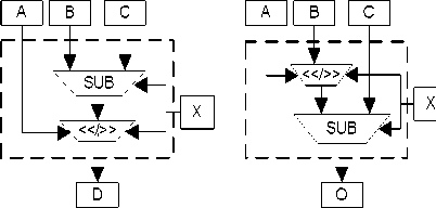
Figure 9. The structure of ADDSM algebra operator
The operator structure graph of bs_write_ue function is shown in Figure 10. The parameters involved in computing and the results of variables can be expressed
as registers, and complex operations are also decomposed into two ALU operations, with inserting a register in the two ALU operations.
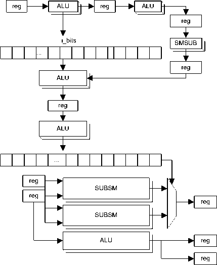
Figure 10. The operator structure graph of bs_write_ue function
-
V. T HE O VERALL H ARDWARE A RCHITECTURE OF
H.264 E NTROPY C ODING
As shown in Figure 11, for UVLC, the syntax parameters, values from the data bus, are firstly registered in the cache, and then parsed for UVLC coding. The syntax analysis includes the calculation of the type of the macroblock and the selection of coding mode. For CAVLC, the coding objection is a 4 × 4 sub-block registered in the cache in certain format at first, and then parsed for CAVLC coding. The analysis mainly refers to a residual sub 4 × 4 block by scanning data to extract the information between them (including the non-zero factor, tailing factor, non-zero coefficients, the total zeros before the last non-zero coefficient, and the number of zeros before each non-zero coefficient) for encoding. Finally, the two parts of bit stream are stitched and exported.
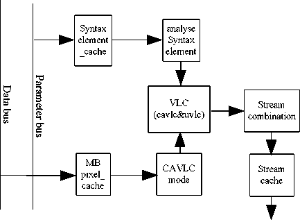
Figure 11. The overall structure of the entropy encoder
There are many operations such as shift-add, add-shift, which are suitable for the unit of operator in the entropy coding algorithm. For hardware sharing of entropy encoding , which consists of a series of operator function blocks, mainly including the Index of Columbus coding, Context-adaptive variable-length coding function block and the bit stream stitching function block, these are used repeatedly to complete the entropy coding function[14].
Operators can construct different blocks with the internal basic structures to implement different functions, these operators function blocks are regular and flexible. Columbus index encoding has two blocks: a signed Columbus index encoding function block and unsigned; for context adaptive variable length coding(CAVLC) block, there are three types: residual coefficients encoded as sub-block 16, 15 and 4. For Stream stitching, there is just one splicing block to complete the task of stream combination.
In the entropy encoder, the function x264_macroblock_write_cavlc complete macroblocklevel coding. The C program is as follows:
264_macroblock_encode_IFrame( h );
if( IS_SKIP( h->mb.i_type ) )
{ i_skip++;
} else { if( h->sh.i_type != SLICE_TYPE_I ) { bs_write_ue( /× skip run ×/ i_skip = 0;
}
The final operator structure is shown in Figure 12 and the core function is x264_macroblock_write_cavlc, which complete slice-level coding, including the coding of the macroblock header and macroblock residual coefficients. The function of bs_write_ue has been illuminated as an example above.
| h->sh.i type [ ■ | h->mb.i_type |
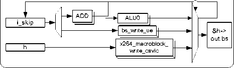
Figure 12. x264_macroblock_ encode_IFrame operator structure
For macroblock type of P-SKIP, the number of the macroblock is recorded, and the i-skip counter will plus one, after which the macroblock coding is over. If it is not P-SKIP macroblockbut non-I frame in the next prediction, the value i-skip recorded in the counter will be encoded by Columbus index coding, and then i-skip register will be cleared, and then carry out the UVLC and CAVLC coding.
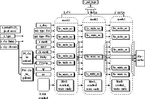
Figure 13. The overall structure of entropy encoder
Through the C code to hardware mapping, shown in Figure 13, x264_macroblock_write_cavlc function completes the macroblock coding. It is divided into two separate units, UVLC and CAVLC, of which UVLC unit is primarily responsible for the Index of Columbus coding, and CAVLC unit is responsible for the macroblock data coding, within the index lookup table coding and the Index of Columbus coding. The specific units included are as follows:
-
a) L0 logic: the mapping of the macroblock type
-
b) I4_cbp_to_golomb: the mapping of index of Columbus coding in I4 macroblock type
-
c) P16_cbp_to_golomb: the mapping of index of Columbus coding in P16 macroblock type
-
d) mux logic: the stitching of bitstream
-
e) bs_write_ue logic: unsigned Index of Columbus coding
-
f) bs_write_se logic: signed Index of Columbus coding
-
g) x264_residual_write_cavlc logic: Context-adaptive variable-length coding
The logic cells constitute the function block of the operator.
The operators used in entropy encoder consist of algebra operators, storage operators, link operators and controlling operators. The result shows that the implementation by operators is regular and clear.
-
VI. E XPERIMENTAL R ESULTS
The proposed hardware architecture was implemented with Verilog-HDL and the functionality of the design was testified correct with RTL simulations using Mentor Graphic ModelSim SE 6.0 by comparing the results with that of the X264 model. Meanwhile, the design was mapping onto a Xilinx Virtex6 XC6VLX240T for FPGA prototyping with a frequency of 88.7MHz and it costs 8879 LUTs, as shown in Table III, which also proved the correctness of the design.
TABLE III. FPGA V ERIFICATION R ESULTS
|
Item |
Report Type |
xc6vlx240t-1ff1156 |
Available Resource |
|
Performance Summary |
Timing constraints |
11.204 ns |
-- |
|
Slice Logic Utilization |
Slice Registers (Flip-Flops) |
3645 (1%) |
301440 FFs |
|
Slice LUTs (6in LUTs) |
10396 (6%) |
150720 6inLUTs |
|
|
Memory: LUTs (For Distributed RAM) |
2 (1%) |
58400 6inLUTs |
|
|
Occupied Slices |
3113 (8%) |
37680 Slices |
The design was finally synthesized with SMIC 0.13um CMOS technology with a clock frequency of 167MHz (6ns). Table IV demonstrates the comparison between the proposed design and several other designs in terms of hardware resources and working frequency. According to Table IV, the proposed design can handle a real-time application of 720P at 60frames/sec with relatively less resource. The performance of HD1080 30fps, mentioned in [8], is the same with that in this paper, which are both superior to that in [9] and [10]; however, it only implemented the CAVLC part of entropy coding. This paper has implemented the combination of CAVLC, UVLC and bit stream stitching MUX, among which CAVLC occupies 40 percents of the whole design. The number of gates in [8] should be revised to 32785, which is comparable with that in this paper, and also the proposed design can work at a higher frequency, which both explicates the superiority in performance of the proposed design architecture and methodology based on operators.
TABLE IV. FPGA V ERIFICATION R ESULTS AND C OMPARISON
|
this paper (UVLC& CAVLC& MUX) |
paper[8] (CAVLC) |
paper [9] (CAVLC) |
paper[10] (CAVLC) |
|
|
Technology |
0.13 pn |
0.18 pn |
0.18µm |
0.35µm |
|
Gate Count |
32998 |
13114 |
17635 |
9171 |
|
Clock Frequency |
167MHz |
133MHZ |
100MHz |
66MHz |
|
clk period |
6ns |
7.5ns |
10ns |
15ns |
|
Performance |
HD720P 60fps |
HD1080 30fps |
HD1080 30fps |
QICF 10fps |
For the proposed CAVLC entropy coder, a set of operator function blocks can be reconfigured for different numbers of residual coefficients for the sub 4 × 4 block coding, with which not only can the proposed design save the hardware resource, but also can it improve the regularity, flexibility and efficiency of the encoder.
As can be seen from Table IV, the proposed design can provide a comparable if not better performance with the previous work, which shows good evidence for the efficiency of the novel design methodology based on operators. The proposed operators can be applied to other multimedia applications and will be added to our HPVOL (High performance video operator library).
Figure 14 shows the comparison between one of the original frame from a 1080P@30fps video sequence and the corresponding decoded frame of the same video sequence encoded by the proposed entropy coder.

Figure 14. Original frame(left) VS decoded frame(right)
The implementation of the proposed design has been accomplished with only 1.5 man-months, which includes C program synthesis, operator structure design and netlist design but not function verification. It shows that the procedure of design has been largely accelerated.
-
VII. C ONCLUSION
Novel design methodology based on operators is proposed and the implementation of H.264 entropy coding with the operator-based design methodology proves the practicability and efficiency of the methodology. The analysis results show that the performance of the implementation is comparable to other ASIC designs based on standard cells. Also, the operator structure is integral and flexible for further modification and optimization. More importantly, the implementation has been accomplished with only 1.5 man-months, which means that the procedure of design has been largely accelerated in the overall flow. The proposed operatorbased design methodology can provide a good approach for the need of rapid design in integrated circuits, as well as obtaining suitable hardware performance. Further works should be done for the platform-based verification of the proposed design methodology in the future.
A CKNOWLEDGMENT
The authors thank all the members of IMS, especially the teammates of S-ASIC group in Peking University Shenzhen graduated school.
References Operator Design Methodology and Application in H.264 Entropy Coding
- Liangwei Ge, Song Chen, Takeshi Yoshimura, “Automatic Implementation of Arithmetic Functions in High-Level Synthesis”. In: 9th international conference on solid-state and integrated circuit technology, 2008.
- Dai Peng, Wang Xin’an, Zhang Xing, “A Novel Reconfigurable Operator Based IC Design Methodology for Multimedia Processing”. In: TENCON, 2009.
- Ziyi Hu, Kuilin Chen, Xin’an Wang. “Operator design methodology and implementation for H.264 entropy encoder”. In :the 2nd international conference on information engineering and computer science, 2010.
- Patent(PCT);“Based on reconfigurable components integrated circuit and design method”;Xin’an Wang, Peng Dai, Ziyi Hu, Yuzhong Jiao;Patent NO. 200810217465.7. (in Chinese)
- ISO/IEC 14496-10 and ITU-T Rec. H.264, Advanced Video Coding, 2003.A. Hallapuro, M. Karczewicz and H. Malvar, Low Complexity Transform and Quantization – Part I: Basic Implementation, JVT document JVT-B038, Geneva, February 2002.
- Gary J. Sullivan, Pankaj Topiwala, and Ajay Luthra, “The H.264/AVC Advanced Video Coding Standard: Overview and Introduction to the Fidelity Range Extensions”, the SPIE Conference on Applications of Digital Image Processing XXVII, August, 2004.
- Iain E. G. Richardson, “H.264 and MPEG-4 Video Compression”, The Robert Gordon University, Aberdeen, UK,pp-160
- Szu-Wei Lee and C.-C. Jay Kuo, “Complexity Modeling of H.264/AVC CAVLC/UVLC Entropy Decoders”, 2008 IEEE,pp-1616
- Houjie Bi. “A new generation of video compression coding standard—H.264/AVC”. Beijin: Posts & Telecom Press.2005. (in Chinese)
- ITU-T. H.264 Recommendations. March,2005.
- Dong Tan. “H.264 baseline profile entropy encoder FPGA Implementation. Electronics and Communication Engineering”.2006. (in Chinese)
- Hongqi Hu, Jiadong Xu. “Novel high efficiency VLSI implementation of CAVLC in H.264/AVC. Computer Engineering and Applications”. 2008, 44(32). (in Chinese)
- Chen T C, Huang Y W,Tsai C Y,etc. “Dual-bloek-Pipelined VLSI architecture of entropy eoding for H.264/AVC baseline profile”, Proeeeding of International SymPosium on VLSI Design, Automation and Test(VLSI-DAT), 2005:271-274.
- Lai Yeong-Kang, Chou Chih-Chung, Chung Yu- Chieh. “A simple and cost effective video eneoder with memory-redueing CAVLC”, ISCAS 2005.
- Yangyuan Wang, Yunwen Wang. “China's IC Industry Development - from the country of consumption to the power industry”. Science Press, pp. 241.May, 2008.(in Chinese)
- P. Coussy, A. Morawiec, “High-Level Synthesis: from Algorithm to Digital Circuit”. Springer, 2008.
- D. Pellerin and S. Thibault, “Practical FPGA Programming in C”, Prentice Hall, 2005.
