Optical-digital system for real-time fingerprint identification

Author: Khonina S.N., Kotlyar V.V., Nalimov A.G., Skidanov R.V., Soifer V.A.
Journal: Компьютерная оптика @computer-optics
Section: Обработка изображений: Восстановление изображений, выявление признаков, распознавание образов
Article in issue: 24, 2002.
Free access
Performance of the optical-digital system for real-time fingerprint identification using a method of the optical construction of the direction field is reported.
Short address: https://sciup.org/14058540
IDR: 14058540
Text of the scientific article Optical-digital system for real-time fingerprint identification
Among systems for fingerprint identification most promising are those that employ both the general structure (correlation comparison, fingerprint Fourier spectrum analysis) and local peculiarities [1, 2]. However, the majority of such systems are at the development stage. In the meantime, the currently applied systems rely exclusively upon the local features for identification (line bifurcation). Such systems feature a very high reliability but as a rule lack an adequate rate of comparison with the database. Consequently, despite a rather short period of less than 1 second the system requires to generate the features (for the present purpose and in further text the time is indicated for the Pentium III processor, 633 Hz) the general identification time for large databases may be too long. The rate of exhaustive search through the database using the fingerprint line bifurcations is no greater than 500 samples per second. With huge modern databases containing tens and hundreds of thousands of samples even structuring the databases in terms of fingerprint types - with use of only local features - is unable to provide the real-time identification.
In this paper we discuss a two-stage fingerprint identification scheme via constructing the direction field followed by the decomposition into the orthogonal basis and determination of global and local special points.
1. The computer-simulation results
The direction field [3, 4] of an image is a function of point coordinates, equal to the angle of tangent to the image intensity level line. For example, if I ( x, y ) is the light intensity over the image the direction field ф x, y ) is given by the expression:
. , _ di(x,y)/dx , _ tgф(x,y) = ,0 < Ф(x,y) < П. (1) di (x, y)/ dy
Obviously, the angle ф x, y ) gives the direction perpendicular to the gradient vector ( d i ( x , y ) / d x , 5 1 ( x , y ) / d y ) .
If the intensity function at a certain local area Q of
fingerprint defined as
q(x, y ) =
1,(x, y )eQ 0,( x, y )gQ ’
is ap-
proximated by a cosine grating we can write cos ( ® x x + to y y ) =
Then, the Fourier transform of the intensity function is
+B ^ A {^ (^ - ®x, n - ®y) + ^(^ + ®x, n + ®y)}+ (3) +B5 (£, n), where (x,y) and (^,n) are the Cartesian coordinates at the input and output planes, 3 is a 2D Fourier transform, and 5(x,y) is the Dirac function.
Thus, the grating produces a 5 -impulse at the center of the Fourier plane and two 5 -impulses found symmetrically on a line that passes through the center of the Fourier plane at an angle 9 :
®v tge = - -y. (4) ®x
In this case, the angle 9 and the angle ф of the carrier direction are related as follows:
7T e = ф+2, (5)
which means that the angle 9 is perpendicular to the inclination angle ф of the grating grooves.
If the grating is limited by some area q(x, y) in the frequency plane we obtain the convolution of the Fou-rier-image of the function that describes this area, Q( ^ , n ), with the 5 -impulses.
It has been known that the convolution of the 5 -function with any function produces the same function with a corresponding displacement:
5(5 - rnx, n - toy)® Q(^, n)^q(- x,-y). (6)
Thus, at the output plane the non-zero intensity will be found only in an area corresponding to a grating with the groove inclination angle of ф .
Note that this effect takes place irrespective of the frequency of the grooves because 5 -functions found on the same ray – closer to or further from the center – will correspond to them. Hence, a segment cut along the
Г n direction e = modп 1ф + -21 will contain the spectra coming from all the gratings with the groove direction of ф, irrespective of the groove frequency and the limiting areas.
By cutting the segments at the top part of the Fourier-plane we are able to scan all line directions found in the image within the range [0, n ).
The numerical implementation has also allowed the method's parameters to be somewhat improved. For example, if in the optical-digital unit the direction field was constructed with regard to four directions the digital method allowed the direction field of eight directions to
be generated at a reasonable time. To input the fingerprints we have developed an input device (Fig. 1) that allows the fingerprint images of 256x256 pixels to be entered.
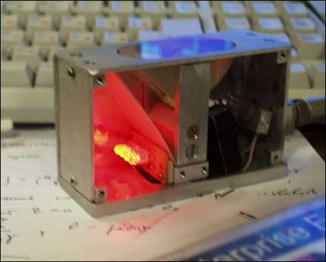
Fig. 1. Unit for fingerprint input
The entered fingerprint is being processed in several stages (Fig. 2). At the first stage, the direction field is generated using the above-described procedure (Fig. 2b). At the second stage, the special points are identified (Fig. 2c). The feature vector is formed using the coefficients of the direction field decomposition in the Ha-damard basis (Fig. 2d) and information on the special points. The feature-vector-aided identification procedure is based on finding a minimal Eucledean distance from the feature vector under study to each database feature vector [3, 4].
The fingerprint special points are points where the direction is not defined. Let us consider the identification of the special points in more detail.
-
2. Special points
The intensity function of a "fringy" image, I(x,y), has a lot of local maximums and minimums and can be characterized by its gradient vI (x, y ) =
5 7 5 7
d x ’ 8y
which is a vector that shows the direction of the greatest intensity change. The gradient can be considered as a complex function:
V I ( x , y ) =V I ( x , У ) ё ф ( x ' y ) =| I + i , (8)
dx dy where
p ( x , y ) = arctg

A is the direction field or
the function of the complex gradient's argument. Obvi- d 7 d 7
ously, at points where — = — = 0, the direction field is dy 9x indeterminate
, 0 ,
which mean that the gradient direc- tion at these points is not determined. It is these points that are called the special points. When passing around these points, the direction field can change its value m times in the range from 0 to 2n, thus the change of the direction field around the special points is Аф(x, y) = 2nm , where m is the index of the special point.
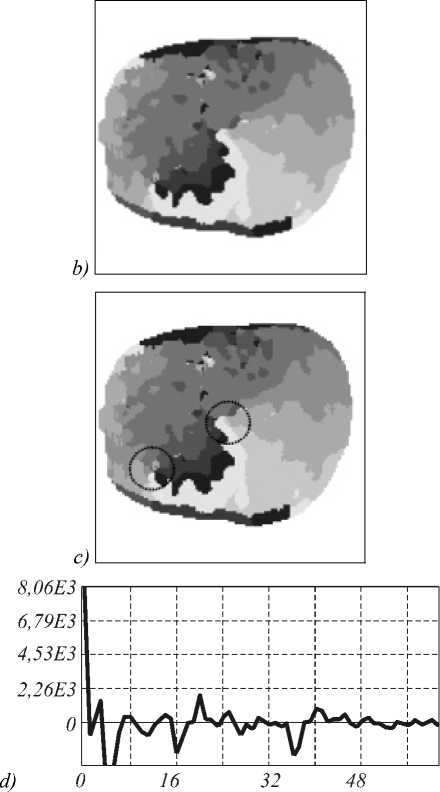
Fig. 2. Fingerprint processing stages:
(a) the entered fingerprint, (b) the direction field,
(c) identifying the special point coordinates, and (d) the resulting feature vector
In Lyapunov's theory of stable solutions, the special points are characterized using the solutions of a characteristic equation. By way of illustration, for a set of two differential equations of the first order
^ x=P ( x • y )
l|=Q (x,y) Idt the characteristic equation takes the form:
d P 8 P
8x dx _ n
dQ dQ -5 -0,
8 x 8 y
where s is the parameter of the characteristic equation.
Since in our case, the indeterminacy of the relation
5y = Q dx P
is equivalent to the indeterminacy of the rela- tion

, we can use the projections of the intensity
81 „ dI function gradient, Q = —, P = —, instead of the func-8x 8y tions P and Q, which gives the characteristic equation in the form dxdy
8 x 2
8 y 2
8 x 8 y
= 0.
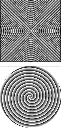
Using the roots of the characteristic equation, S1 and S2, we can identify the type of a special point. Saddle (referred to as "delta" in criminology) takes place under the condition that Im S i = 0, S 1 S 2 < 0 (Fig. 3a). Focus ("spiral") takes place when S * = S 2 ,Re S 1 Re S 2 > 0 (Fig. 3b). Center (no exact equivalent in criminology, with a "loop" matching best) is shown in Fig. 3c.
Depending on the combination of special points, various fingerprint patterns are extracted, which allows undoubtedly non-matching fingerprints to be sifted off as early as at this stage.
In identifying the special points, the direction field quantized in 8 levels is used. To exclude the noise points, the initial direction field undergoes rank filtration. The filtered direction field is scanned with a mask of specified size. At each mask position, the number of directions found within the mask and the number of points for every direction are calculated. For every mask position, a number that defines the probability for a given point (at the mask center) to be special is determined. This number is equal to the product of the numbers equal to the number of points of a given direction. As a result of such a definition of the "specialty" factor (probability), the value of P at the special points attains its local maximum.
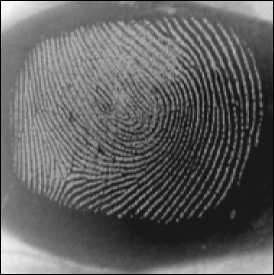
Figure 4b shows an example of processing of the direction field that was derived for the fingerprint in Fig. 4a, with the special spots extracted.
The special points are used for a previous structuring of the fingerprint database. Once the special points have been identified, a feature vector graphically shown in Fig. 2d is being constructed.
I^^B)
c)
Fig. 3. Major types of special points: (а) saddle (delta), (b) focus (spiral), and (c) center (loop)
The direction field also makes it possible to find local peculiarities in the fingerprint images, namely, the line bifurcations. Figure 5 depicts the result of operation of an algorithm that finds the line bifurcations using the direction field.
In the direction field areas are being identified where three or more directions are found in proximity. It is this location that is taken to be the line bifurcation. From Fig. 5, the majority of bifurcations can be identified using the direction field. This property of the direction field enabling the determining of minute fingerprint features can be employed for constructing a two-stage identification scheme.
-
3. Two-stage identification scheme
A two-stage identification scheme is proposed. First, a small group of fingerprints with minimal Eucle-dean distance to the base vector in the global feature space is extracted. The required computational efforts for such a procedure are by four orders of magnitude less compared to the identification based on fingerprint line bifurcation. Then, the refined identification is conducted within the extracted group using the local features.
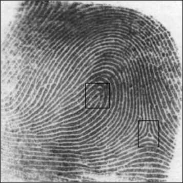
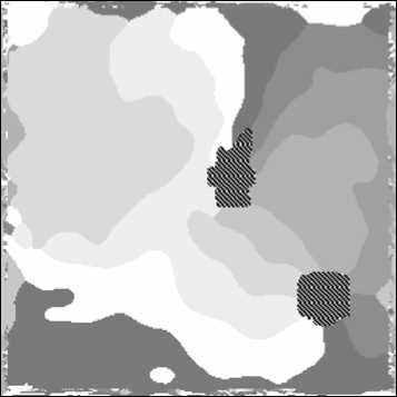
Fig. 4. An example of direction field processing:
(b) threshold processing. The positions of the corresponding special points are within squares in the fingerprint image (a)
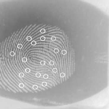
Fig. 5. Fingerprint bifurcations found using the direction field
Thus, the two-stage procedure aimed at reducing the identification time is as follows:
-
1. The global features vector is constructed based on the direction field decomposition into the orthogonal basis and information on the special points. A group of fingerprints is extracted for which the distance in the global feature space to the database fingerprint is less than a specified threshold distance.
-
2. The fingerprints in the extracted group are additionally processed in order to identify the bifurcations' location (local special points). The fingerprint is then identified based on the maximal number of matching bifurcation points (i.e. using a classical technique).
The algorithm's operation was computer simulated. The database used consisted of 57 fingerprint samples. 120 newly taken samples of every fingerprint contained in the database were analyzed. Thus, 6840 experiments were conducted. With a one-stage identification based solely on the Hadamard coefficients the reliability was 99.4%. With the two-stage identification, first groups of best matching samples composed from one to three candidates found within the distance R p from the fingerprint under analysis were extracted. The final decision was then made via analyzing the bifurcation positions - on the basis of the maximum number of matches. With this method, only two false identifications took place, pushing the reliability to 0.9997%. The global-feature-aided identification has taken only 16 ms, whereas the identification based on the fingerprint line bifurcation analysis requires 231 ms.
Conclusion
We have demonstrated a possibility of using the direction field for real-time fingerprint identification. The use of a two-stage identification scheme has been justified. High reliability of the two-stage scheme has been experimentally proved.
