Optimal choice of design parameters of the umbrella-type antenna spoke to reach maximal bending stiffness

Author: Lopatin A.V., Rutkovskaya M.A.
Journal: Сибирский аэрокосмический журнал @vestnik-sibsau
Section: Авиационная и ракетно-космическая техника
Article in issue: 3 т.19, 2018.
Free access
The paper is devoted to cross-section geometrical parameters optimization of thin-walled spokes of large-size, um- brella-type deployable satellite parabolic antennas with radial spokes. The spokes in the structures mentioned above must have maximal bending stiffness and minimal mass. Spokes with uniform thickness of walls both in the section and along their lengths are not optimal to achieve the maximal stiffness while keeping predetermined mass, because they have the same bending stiffness in any direction. In the given paper the authors suggest changing the shape of the spoke cross-section by using sections of different thicknesses. This would allow increasing the bending stiffness of each spoke in the perpendicular to the antenna surface direction while preserving the same mass of the complete structure. The thickness will be increased stepwise in the cross-sectional areas of the maximum distance from each other in the bend plane; in the remaining part of the section it will be reduced. The main objective of this paper is to obtain analytical dependences for assessment of the bending stiffness of the cross section of the umbrella-type antenna spoke with a stepwise change in its thickness. Formulas were obtained within the framework of the beam theory of bending. The obtained analytical dependencies were verified by numerical simulation in the finite element software Ansys. Verification of the obtained results by numerical simulation showed good convergence with theoretical conclusions. The formulas obtained in the paper make it possible to give practical recommendations for design of large deploy- able space antennas with improved parameters, namely maximum stiffness with minimum mass of the structure.
Deployable structures, umbrella-type antenna
Short address: https://sciup.org/148321863
IDR: 148321863 | UDC: 539.3 | DOI: 10.31772/2587-6066-2018-19-3-504-509
Выбор геометрических параметров спицы зонтичной антенны для обеспечения максимальной изгибной жесткости
Рассмотрена оптимизация геометрии поперечного сечения тонкостенных спиц крупногабаритных разво- рачиваемых спутниковых параболических антенн зонтичного типа с радиальными спицами-ребрами. В подоб- ной конструкции спицы должны обладать максимальной изгибной жесткостью при минимальной массе. Спицы с постоянной толщиной стенки как в отдельном сечении, так и по длине не являются оптимальными для достижения максимальной жесткости при заданной массе, так как имеют одинаковую жесткость при изгибе в любом направлении. Предлагается изменить форму поперечного сечения спицы за счет использования участков различной толщины. Это позволит увеличить изгибную жесткость спицы в направлении, перпендикулярном поверхности антенны при сохранении заданной массы конструкции. В областях сечений, максимально удалённых друг от друга, в плоскости изгиба толщина будет ступенчато увеличена, в оставшейся части сечения - уменьшена. Основной целью данной работы явилось получение аналитических зависимостей для оценки изгибной же- сткости поперечного сечения спицы зонтичной антенны со ступенчатым изменением ее толщины. Формулы были получены в рамках балочной теории изгиба. Полученные аналитические зависимости были проверены численным моделированием в универсальной программной системе конечно-элементного анализа Ansys. Вери- фикация полученных результатов численным моделированием показала хорошую сходимость с теоретически- ми выводами. Полученные в статье формулы позволяют дать практические рекомендации по конструированию больших разворачиваемых космических антенн с улучшенными параметрами, а именно, максимальной жесткостью при минимальной массе конструкции.
Text of the scientific article Optimal choice of design parameters of the umbrella-type antenna spoke to reach maximal bending stiffness
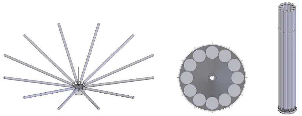
Introduction. Large deployable parabolic antennas are widely used in satellite communication systems. Umbrella-type constructions with radial spokes-ribs connected at one end to the base are the most widespread among such systems (fig. 1).
Spokes are the main supporting elements of an umbrella-type antenna. They must have bending stiffness sufficient to open the antenna and to tense the netting both during the orbital operation and during ground testing of the structure. There are several approaches to the design of the spokes of the umbrella-type antenna [1–14]. Winding is the most technologically feasible method for manufacturing a thin-walled spoke. In the process of winding a strip of unidirectional composite material is laid layer by layer on a cylindrical mandrel at the angle ±ϕ to the longitudinal axis (fig. 2). With a large number of thin, alternating layers with angles +φ and –φ, the structure of a spoke wall can be considered homogeneous and orthotropic.
The main types of spoke deformation are bending in the zoy plane and bending in the zox plane. Bending in the zoy plane occurs when the spoke is loaded with forces that arise during the process of membrane tension. The membrane tension is the main load case for the umbrellatype antenna's spoke. Therefore, the stiffness of the spoke bending in the zoy plane should be greater than the stiffness of the spoke bending in the zox plane. Cross section
of constant thickness is not optimal for achieving maximum stiffness with a given mass.
Optimization of the cross-section geometric parameters of the umbrella-type antenna’s spoke. The authors propose to change the shape of the spoke crosssection by using sections of different thicknesses to increase the bending stiffness of the thin-walled spoke of the umbrella-type antenna while maintaining the specified design mass (fig. 3). An important circumstance is the fact that such a design is technologically feasible.
We connect the longitudinal axis of the spoke passing through the centers of the cross sections with the coordinate z counted from the base (fig. 2) and assign the crosssection of the spoke to the coordinate system xoy (fig. 4). To maintain the specified mass of the structure, it is necessary to ensure the equality of the cross-sectional areas of the spokes in question (fig. 4, 5), which can be achieved by using the cross-section shown in fig 4, 5. Formulas are obtained that allow estimating the bending stiffness of the spoke cross section in the case when the thickness varies stepwise (fig. 5).
Let us define the bending stiffness of the cross section of the spoke. Calculation of a thin-walled rod with a closed cross-sectional contour is carried out on the basis of the hypotheses of the beam theory, according to which the cross section is not deformed and turns like a hard disk when bending.
а b
Fig. 1. An umbrella-type antenna with spokes with a circular cross section: a – an antenna in the deployed position; b – the start position of an antenna
Рис. 1. Зонтичная антенна со спицами с круглым поперечным сечением: а – в развернутом положении; б – в стартовом положении
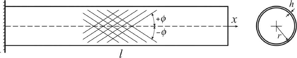
Fig. 2. A cantilever thin walled spoke with a round cross-section
\\\\\\\\\\\\\\\
Рис. 2. Консольная тонкостенная спица с круглым поперечным сечением
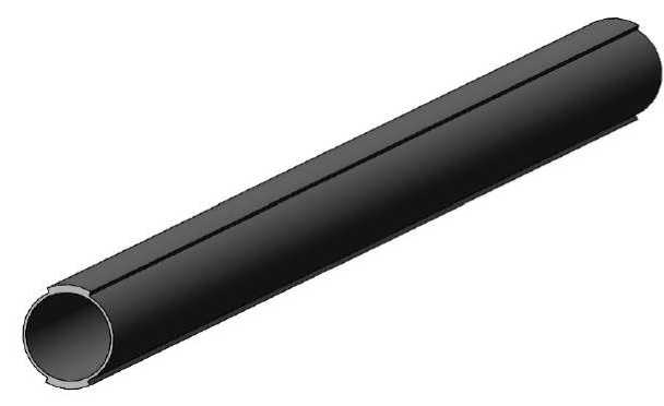
Fig. 3. An isometric view of the spoke with variable thickness
Рис. 3. Общий вид спицы с переменным сечением
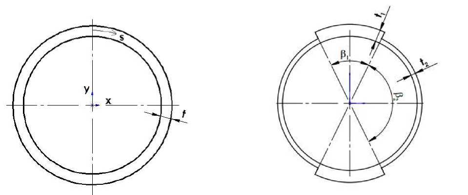
Fig. 5. A thin-walled round spoke with variable thickness in the cross section
Fig. 4. A thin-walled round spoke with constant thickness in the cross section
Рис. 4. Спица с гладким поперечным сечением
Рис. 5. Спица с переменным поперечным сечением
Within the framework of the beam theory [15], the bending stiffness of the cross-section in the planes zoy and zox are defined as follows:
D x = ( Bii y 2 ds , D y = ( Bii x 2 ds . (1)
Here s is the contour coordinate, which is calculated from the formula s = R β, respectively ds = Rd β. The value В 11 denotes the stiffness of the spoke wall when stretched or compressed in the axial direction.
After some transformations (5) we obtain the following expression:
Dx = AnR 3 ( t i ( p i + sin p i ) + 1 2 ( n- ( p i + sin p i ))). (6)
Taking into account the equality of the cross-sectional areas of the two spokes under consideration, we obtain expressions for the bending stiffness of a spoke with a smooth cross-section:
x = R sin P , y = R cos P . (2)
Substituting (2) into (1), we obtain the following expressions:
Dx = ( Bii R 2 cos2 P Rd P = R 3 ( Bii cos2 P d P ,
D
y
=
The rigidity of a spoke with a smooth cross-section will be expressed with the following form:
D = A n R 3 1 2 ( n + P i ( a- i)), (7)
and a cross-section with variable thickness:
D x = A n R 3 1 2 (( a- i)( P i + sin p i ) + n ), (8)
where α = t 1 / t 2 .
The bending stiffness relations can be written in the following form:
n =
D x D
= i +
sin P i
n
P i +---- 7
a- i
D = n Bii R 3 = n AutR 3 . (4)
For a spoke with a complex cross-section (fig. 5), the expression for the bending stiffness of the cross section in the zoy plane takes the form:
Dx = 2 R 3
(
Ant i J cos P d P + An1 2
V
^+₽ 2
J cos2 p d P +
5 l
+ A ii t i
2 22
J cos2 p d P
Pi у+e2
where β2 = π – β1.
The results of the calculations are shown in the graph (fig. 6) for different thickness ratios α. Here α1 = 1.5, α 2 = 2.0, α 3 = 3.0, α 4 = 4.0, α 5 = 5.0.
As it can be seen from the graph, the maximum stiffness is achieved when the ratio of the thicknesses of the spoke with the variable cross-section is 5 and the angle β 1 is equal to 62°.
Modal analysis of the spokes by the finite element method was carried out (fig. 7) to verify the results. The spokes are made of CFRP (Carbon Fiber Reinforced Polymer) with the following characteristics: modulus of elasticity is 100 hPa, Poisson’s ratio is 0.3, and density is 1500 kg / m3. The internal diameter of the spoke is 200 mm, the length is 6 m, the thickness of the smooth cross-section is t = 2 mm.
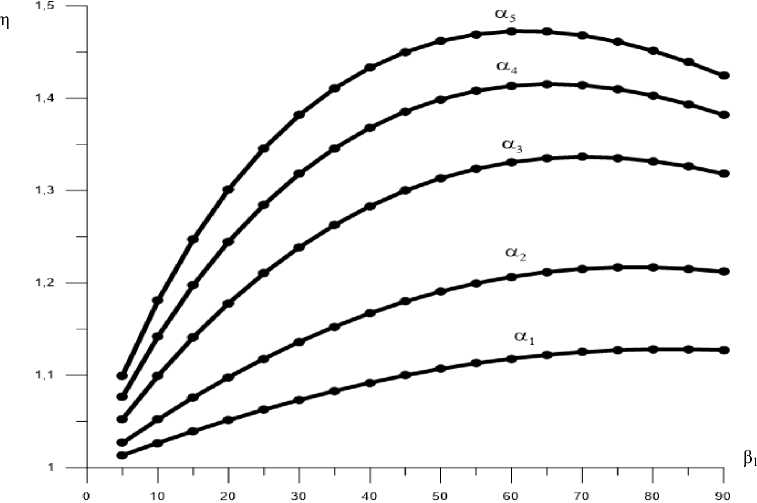
Fig. 6. The dependence of the stiffness parameter on the angle β 1 at different thickness ratios
Рис. 6. Зависимость жесткостного параметра от угла β 1 при разных соотношениях толщин
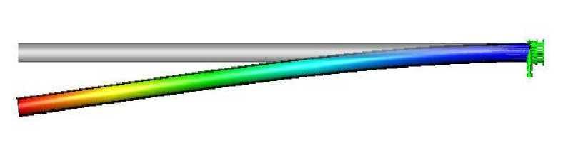
Fig. 7. The modal analysis of a spoke with a variable cross-section
Рис. 7. Модальный анализ спицы с переменным поперечным сечением
Taking into account the equality of the areas of the two cross-sections, we obtain the parameters for a spoke with a variable cross-section: the angle β1 is 60°, the thickness t 1 = 4 mm and t 2 = 1 mm. With these geometric parameters, the masses of the spokes are practically equal.
The first frequency of a spoke with a smooth crosssection is 8.69 Hz, and that of a spoke with a variable cross-section is 10.64 Hz. As a result of the calculation it can be seen that the stiffness of a spoke with a variable cross-section significantly increased in comparison with a spoke with a smooth cross-section. The ratio of stiffness obtained numerically is 1.47.
The conclusion. Substituting the calculated parameters of the spokes into expression (9), we obtain η1 =1.41. Verification of the results obtained showed good convergence with theoretical conclusions.
Thus, the formulas obtained make it possible to estimate the bending stiffness of the cross-section of the umbrella-type antenna spoke when its thickness varies stepwise and give practical recommendations for the design of large expandable space antennas with improved parameters, namely, maximum stiffness with a minimum mass of the structure.
Acknowledgments. This work was supported by the Ministry of Education and Science of the Russian Federation № RFMEFI57517X0144.
References Optimal choice of design parameters of the umbrella-type antenna spoke to reach maximal bending stiffness
- Akira M. In-orbit deployment performance of large satellite antennas // J. Spacecraft and Rockets. 1996. Vol. 33, № 2. С. 222-227.
- Barho R. Investigations into deployment complications of the ERS-1 SAR antenna // 5th European Space Mech. and Tribol. Symposium (Noordwijk, 28-30 Oct., 1992). Paris, 1993. С. 61-64.
- Freeland R. E. Survey of deployable antenna concepts // Proceedings of the large space antenna systems technology workshop. NASA CP-2269. Pt. 1. 1983.
- Gantes C. J., Konitopoulou E. Geometric design of arbitrarily curved bi-stable deployable arches with discrete joint size // International Journal of Solids and Structures. 2004. № 41. С. 5517-5540.
- Imbriale W. Spaceborne Antennas for Planetary Exploration. NJ.: John Wiley and Sons, 2006. 592 c.
