Optimal control of deployment of the spoke of a transformable reflector in the presence of disturbance

Author: Kabanov S.A., Kabanov D.S., Nikulin E.N., Mitin F.V.
Journal: Siberian Aerospace Journal @vestnik-sibsau-en
Section: Aviation and spacecraft engineering
Article in issue: 4 vol.22, 2021.
Free access
One of the promising types of spacecrafts are large-size transformable reflectors. Such apparatuses are delivered to a target orbit folded, and then deployed to a working condition. The large aperture allows sig-nificantly expanding the capabilities of the antenna. In this case, the tasks arise of a smooth and reliable deployment, adjusting the shape of a radio-reflecting net, and adjusting the orbital position. Due to the fact that the deployment process takes a long time, accounting for disturbing influences is an important prob-lem. The presence of radiation, large temperature differences, solar wind affect the entire system and main-ly on the directional diagram. It is also necessary to smoothly deploy the structural elements, since with an increase in the diameter of the radio-reflecting surface, the moments of inertia of the antenna increase, which leads to prolonged oscillations. In this paper, the process of deployment of the reflector spokes in the presence of disturbances and measurement errors is considered. The solution to the problem is presented using the separation theorem. To estimate the parameters of the system in the presence of measurement noise, the Kalman filter is applied. Its performance is shown at various values of the noise intensity. A ran-dom process such as white noise was selected as external disturbances and measurement noises. The con-trol problem is solved using the optimal control algorithm according to the hierarchy of target criteria. The possibility of minimizing energy costs by means of interval switching on of measuring sensors is shown. The results of numerical simulation are presented.
Sequential optimization algorithm, large-size transformable reflector, optimal filtration, mathematical model, modeling
Short address: https://sciup.org/148329596
IDR: 148329596 | UDC: 517.977.5-629.783 | DOI: 10.31772/2712-8970-2021-22-4-649-659
Text of the scientific article Optimal control of deployment of the spoke of a transformable reflector in the presence of disturbance
Space antennas play an indispensable role in aerospace communications, military reconnaissance, deep space sensing, global broadcasting, Earth remote sensing, and climate forecasting. Because of the limitations imposed by a launch vehicle, deployable antennas are widely used [1–3]. They are placed in the fairing during the launch phase, after reaching the orbit the deployment process begins, and finally the parabolic reflecting surfaces are formed. Stable and reliable deployment of the reflector largely ensures the success of the space mission.
Since the late 1960s, large-sized transformable antennas have been actively used because of their large aperture and low mass. At present, the Astro Mesh Reflector is the most perfect and reliable deployable antenna available [4; 5]. The deployment process is completed by fixing the truss and forming the desired shape of the reflective surface.
For the vast majority of such designs, deployment is irreversible and there are no effective ways to maintain and actively adjust the radio-reflective net in orbit. It is important to study and simulate the deployment process at the design stage to get a deep understanding of the deployment dynamics [6]. The complex kinematic and dynamic behavior of the system, high nonlinear stresses and different cable network topologies, as well as energy dissipation caused by friction, damping, and gaps significantly affect the deployment dynamics of large-sized transformable antennas. Research in dynamic modeling for the deployment of different types of structures is actively being conducted [7; 8].
Here we consider the realization of a large-sized space construction using a cable system to create the necessary shape of the radio-reflecting surface of the reflector (Fig. 1) [9–12]. A large-size trans- formable reflector (LTR) consists of a spacecraft (SC) 1. It has deployable elements attached to it, such as solar panels 2, irradiating system 3. To provide a given directional pattern, the boom 4 extends the reflector 5 to the required focal distance. The reflective surface is the netweave 6.
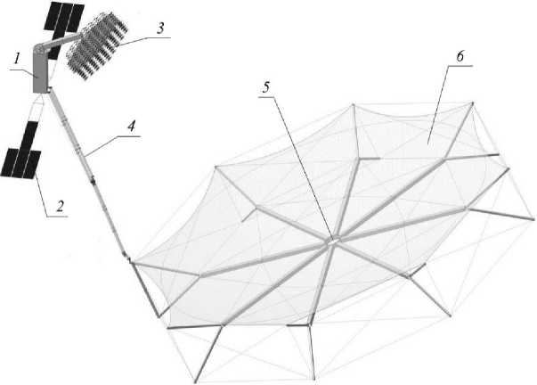
Рис. 1. Конструкция КТР
Fig. 1. The design of the LTR (Large-sized transformable reflector)
The important problem at opening of the LTR from the folded position into the set position with high accuracy of an output to stops is the account of perturbing influences. Also it is necessary to smoothly open elements of the structure, as with increase in diameter of a radio-reflecting surface the moments of inertia of the antenna increase, that leads to long damping oscillations. The presence of radiation, large temperature differences, and solar wind affect the entire system, and mainly the direc- tional diagram [13; 14]. Therefore, it is necessary to solve the problems of filtering and control of the reflector opening.
Mathematical description of the problem
Consider the process of direct opening of a LTR spoke. It is necessary to change the position of the spoke by a given angle φ under the action of force M (Fig. 2). The spoke is rigidly fixed with one end to the SC, the rotation is carried out under the action of an electric motor.
The mathematical model describing this process has the form X = f ( X , u , t ) + ξ x , where X = (φ ω a 1 V 1 a )T is state vector; ξ x = [ ξ x 1 ξ x 2 ξ x 3 ξ x 4 ]T are disturbances with intensity B x = diag ( B x 1 , B x 2 , B x 3 B x 4 ); u is control vector; t is time; φ is spoke rotation angle; ω is spoke rotation
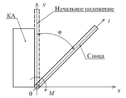
Рис. 2. Разведение спицы рефлектора
Fig. 2. Spreading of the reflector spoke
angular velocity; a 1 and V 1 a are time-dependent bending and spoke bending velocity, respectively. In the element-by-element form, the system is represented as follows [15]:
Ф = ®+^ x1 ,
M (U , ф , Й )
® =----- J-----+ S x 2
a 1 ( t ) = V i a ( t ) + ^ x 3 ,
V 1 a ( t ) = - E bend q 4 [ a 1 ( t ) + Y V a ( t ) ] + M ( U ^) + ^ x 4 ,
P S L J P Sb1( L) Rd where I is the moment of inertia of the spoke; E is the modulus of elasticity; Ibend is the bending moment of inertia; ρ is the material density of a spoke; S is the area of a spoke in a cross-section; l is the spoke length coordinate; γ is the damping coefficient; M is total moment acting on the spoke: M(U, φ, ω) = Mp(U) – Mfr – Mstop(φ, ω) – Мf(φ, ω); Mp is the net torque produced by the commutatorless machine; U is the supply voltage of the commutatorless machine; Mfr is the friction torque; Mstop is the moment created by a stop; Мf is the moment created by a fixer; h(t, l) = a1(t)b1(l) is spoke bending [10; 11; 15; 16]; a1(t) are functions of time t only; b1(l) are functions of coordinate l only; q1 = Z/L, where Z1 = 1,875, L is the total length of the spoke; Rd is the radius of the motor shaft.
The control is performed by changing the supply voltage of the commutatorless machine U , | U | ≤ U max ( U max = 12.5 V). The net torque depends on the control U [10] M p = m ph pE 0 U sin 3 / (Ш р Х ), where m ph is the number of rotor phases; p is the number of pole pairs of magnetic field; E 0 is the effective value of electromotive force (EMF) on stator winding; 3 is the mismatch angle (between U and E o , for motor it is within [0, π/2]); ω p is the angular speed of motor rotor; X s is the synchronous resistance.
We consider the spoke as a cylindrical tube. Let's take it as a single-link construction. The angle of rotation of the spoke and the bend at its end are available for measurement. For the problem of spoke separation, we consider the equations of observation in the form of z = h (x, t) + § z, (2)
where z = [ z 1 z 2 ]T, h ( x , t ) = [φ d ( L )]T, ( d ( L ) = a( t ) b ( L )), ξ z = [ ξ z 1 ξ z 2 ]T are random processes of white noise type with intensity B z = diag ( B z 1 , B z 2 ).
In accordance with the separation principle, the control problem is preceded by the problem of estimating the state vector by incomplete data given by equation (2) [17 –19] . The optimal estimation can be obtained with a Kalman filter, the equations of which for this problem will be of the form
л
^ = ® + R 11 B z! ( Z1 ф ) + R 13 b i ( L ) B z2 ( Z 2 d ) ,
^ = — + R 21 B Z1 ( Z 1 - ф ) + R 23 b 1 ( L ) B z - 2 ( z 2 - d ) , dt I
J = V 1 a + R 31 Bz 1 ( Z 1 ф) + R 33 b 1 ( L ) Bz2 ( Z 2 d ) ,
dV ˆ 1 a dt
EI
--из- q 1 ( a 1 P S x
+ Y V 1 a ) +
2 M
P Sb 1 ( L ) R d
+
+ R 41 B^ ( Z 1 - ф ) + R 43 b ( L ) B z ’2 ( z 2 - d ) ,
R = f x R + Rf T - Rh T B - 'h x R + B x ,
R ( 1 0 ) = R 0 .
Here fx = df /dx , hx =dh/5x, h
10 0 0
0 0 b 1 ( L ) 0
The spoke is driven by an actuator, which is represented by a Phytron phySPACE series commutatorless electric motor [20]. The accuracy is 3–5% for 1.8º. A RangeVision Standard Plus laser scanner with an accuracy of ±0.03 mm is used to measure the spoke deflection h [21]. A LIR-MA208 encoder [22] with an accuracy of ±1º is used as an angular position sensor.
Требуется перевести спицу из начального положения X (0) = (0 0 0 0)T в конечное X ( t f ) = (π/2 0 0 0)T с отсутсвием перерегулирования по углу разворота φ за время t f = 90 c при наличии внешних возмущений ξ x и шумов измерений ξ z .
It is required to move the spoke from the initial position X (0) = (0 0 0 0)T to the final X ( t f ) = (π/2 0 0 0)T with no overshoot in the rotation angle φ for a time t f = 90 s in the presence of external perturbations ξ x and measurement noise ξ z .
Statement of the control problem
We consider a hierarchy of target functionals of the form
J 1 = V f 1 ( X , t f ), (5)
tf
J 2 = V f 2 ( X , t f ) + f L f o ( X , t ) + 0,5( u 2 + u 2 )2 k -2 ] dt , (6)
t 0
where V f 1 = 0,5β 1 [ω( t f ) – ω f ]2; V f 2 = 0,5Δ X f T ρ k Δ X f ; f 0 = 0,5β 2 [φ( t ) – φ f ]2 + 0,5β 3 h 2; α = diag (α 1 , α 2 , α 3 , α 4 ); β 1 , β 2 , β 3 , k are given coefficients; Δ X f = X ( t f ) – X f , X f = (φ f ω f a 1 f V 1 af )T are the given final values of the corresponding variables in (1). Since h ( t , L ) = a 1 ( t ) b 1 ( L ), V 1 a ( t , L ) = V 1 a ( t ) b 1 ( L ), then a 1 ( t ) = h ( t , L )/ b 1 ( L ) and a 1 ( t f ) = h ( t f , L ) / b 1 ( L ).
The solution of the control problem of spokes dilution according to a hierarchy of criteria in deterministic formulation is presented in detail in [16]. The control problem was also solved by control algorithms by the maximum principle using numerical methods of Newton and Krylov – Chernousko, an algorithm based on the PID control structure, and an algorithm of control structure parameter correction [10; 11; 15]. The application of the sequential optimization algorithm according to the hierarchy of target criteria makes it possible to solve the problem in real time with the absence of long damping oscillations after the spoke reaches a given angle of turn. With the help of this algorithm, it is possible to achieve the required accuracy and quality of system control.
Modeling
We take the time of opening of a spoke t f = 90 s, the maximum permissible amplitude of deflection h max = 10 mm. Value of attenuation coefficient γ = 0.04 s. Number of rotor phases m ph = 2, number of pole pairs of magnetic field p = 2, effective value of EMF in stator winding E 0 = 2,5 V, synchronous resistance X; = 2240-3Ohm, mismatch angle between rotor and stator field & = n/10 at any load, ω p =247 rad/s.
The following parameters of the spoke were taken at modeling [10]: material ABS plastic QHF -0140: material density ρ = 1600 kg/m3, modulus of elasticity (Young) E = 1,2∙1011 Pa, spoke length a
= 9,75 m, spoke mass (all the nested links) m = 32 kg. We consider a spoke with ring-shaped crosssection with outer radius R = 0.26 m and inner radius r = 0,25 m. The moment of inertia I will be equal to I = mR 2 /2 + ma 2 /3 = 1015,4 kg • m2. Bending moment of inertia I bend = n R 35 = 5,5240-4 m4, where 5 is the thickness of the pipe (spoke) wall.
We assume that the perturbations do not exceed ±1 % of the maximum values of the corresponding variables. In the calculations, noises ξ x and ξ z were assumed to be white with intensities B x = diag (0,02, 0, 0.0001, 0), B z = diag (0,02, 0,0005) respectively. The initial values of the estimation errors were given as: ф( 1 0) = ф( 1 0) + А ф( 1 0) , и( 1 0) = и( 1 0) + А и( 1 0), a 1 ( 1 0) = a 1 ( 1 0) + A a 1 ( 1 0), V a ( 1 0 ) = V a ( 1 0 ) + A V a ( 1 0 ), where Аф( t o ) = 0.1 rad, A®( t o ) = 0.002 rad/s, Aa 1 ( t o ) = 5 • 10-5 m, A V 1 a ( 1 0 ) = 0.01 m/s.
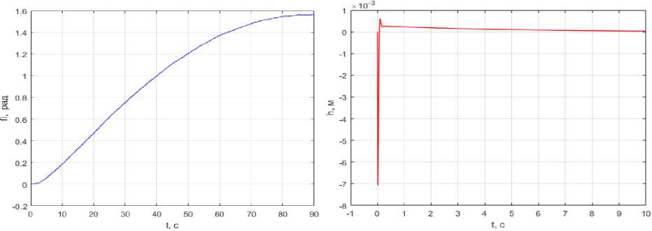
Fig. 3 shows the simulation results: graphs of dependences φ( t ) (over the entire optimization interval) and h(t) (over the first 10 s). One can see that it was possible to solve the problem, i.e. to open the spoke from the initial position by a given angle π/2.
а б
Рис. 3. Графики: a – φ( t ); б – h ( t )
Fig. 3. Graphs: a – φ( t ); b – h ( t )
The maximum deflection of the spoke h ( t ) = 7∙10–3 m is observed at the initial moment of time, thereafter, it smoothly tends to zero. When using the algorithm of sequential optimization according to the hierarchy of two target criteria, the stop and fixing mechanisms do not lead to additional oscillations of the unfolded antenna because of the smooth approach to the final state.
The optimal filtering and control algorithms successfully solve the problem under the selected perturbations and measurement noise. The deviations of the initial values of the variables can be chosen from the range ±7 % of the maximum values of the corresponding quantities, otherwise the correction of the weighting coefficients is required.
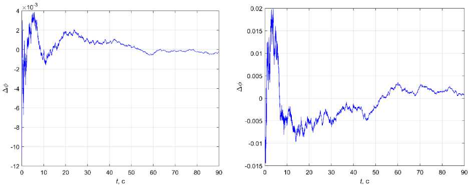
Fig. 4, a shows a graph of the change in the estimation error Δφ at B z = diag (0,02, 0,0005) and in the absence of external disturbances. Fig. 4, b shows a similar curve when the intensity of B z is tripled. The largest error is reached at the beginning of the modelling, then it tends to zero (also for other Δφ( t 0 )). In the presence of external perturbations, the errors have a mathematical expectation equal to zero and a variance not exceeding the variance of the perturbations.
б
Рис. 4. Графики Δφ при различных уровнях интенсивности шума
Fig. 4. Graphs of Δφ at different levels of noise intensity
а
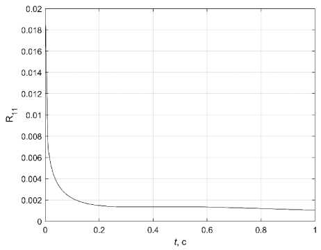
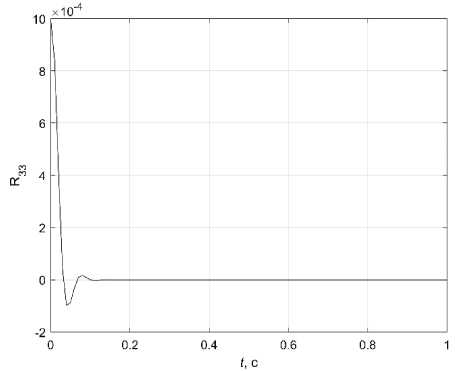
Fig. 5 shows the diagonal elements of the covariance matrix at R 11 (0) = 0,017; R 22 (0) = 0,0002; R 33 (0) = 0,001; R 44 (0) = 0. Rather quickly they come to steady-state values. A simulation with different initial values of diagonal elements of the covariance matrix and different intensity of noise measurements was performed, and the Kalman filter successfully worked out for all variants.
б
Рис. 5. Графики: а – R 11 ( t ); б – R 33 ( t )
Fig. 5. Graphs: a – R 11 ( t ); b – R 33 ( t )
To minimize energy costs, it was proposed to periodically turn off the operation of the sensors and to calculate the state estimation at these sections by predicting using equations (3), (4) at B - 1 = 0 and B - 1 = 0. This made it possible to successfully solve the control problem at lower energy costs. When the sensors are turned off, no energy is expended for their operation and data transmission.
Fig. 6 shows a graph of R 11 ( t )
A1 =- V B z 1 - 1 - R 132 b 1 B z 2 - 1 + 2 R 12 + B x1
with periodic disconnection of measurements from the sensors. Each time the measurements are switched on, the elements of the covariance matrix reach a steady-state value. In the equation for R 11
the summands R 2 B - 1 and R 2 b B - 1 characterize the rate of arrival of information, their absence when the measurements are switched off leads to the increase of R 11 .
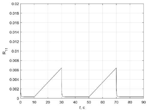
Рис. 6. График R 11 ( t )
Fig. 6. Graph R 11 ( t )
For successful solution of the problem and accurate fulfillment of the terminal conditions it is necessary to switch on the sensors measuring the state of the system at the final section of the optimization interval. The longer the sensor inclusion time at the end of the simulation, the more accurately the problem can be solved. Determining the optimal interval for switching on measurements is an independent scientific and technical task. If the intensity of external disturbances B x increases, it is necessary to measure the system state for a longer time. At a given B x = diag (0,02, 0, 0,0001, 0) for successful solution of the problem it is enough to switch on sensors in the period from 85 to 90 sec. If the disturbance values are doubled, it is necessary to increase the observation time in the final section to 15 s. Sensor operation time depends on type and intensity of external disturbances, requirements to permissible energy consumption value. As a result of statistical modeling the estimation of mathematical expectation of criterion (5) is M ( J 1 ) = 0, criterion (6) M ( J 2 ) = 0,035, where for one of the variants the following value φ( t f ) = 1.576 is obtained.
A separate task is to determine the switching off time of the sensors measuring the angular position of the spoke and the deflection value independently of each other. Thus, in order to fulfill the terminal condition for the angle φ for a given perturbation, it is necessary to observe the last 5 s of the simulation, whereas for the deflection h , 3 s of observation are sufficient. The values of φ and h depend on the applied moment M . The value of h at the end of the opening with the selected control does not exceed 5∙10-5 m, which corresponds to the accuracy of the sensor. Therefore, the value of the deflection at the final moment can be neglected.
Conclusion
As a result of this work, the solution of the problem of optimal control of the stochastic LTR spoke opening model by incomplete data using the separation principle was confirmed. Using a sequential optimization algorithm with the data estimated using the Kalman filter allowed us to solve the problem under different intensities of disturbances and measurement noise. The interval switching off of measurements allows to reduce the energy consumption for sensor powering and measurement processing. Further work involves setting and solving the problem of optimizing the observation intervals to minimize the energy costs [23].
The presented research was reported at the XXII International Scientific Conference «System Analysis, Control and Navigation» [24].
References Optimal control of deployment of the spoke of a transformable reflector in the presence of disturbance
- Puig L., Barton A., Rando N. A review on large deployable structures for astrophysics missions. Acta Astronautica. 2019, Vol. 67(1), P. 12–26.
- Polyanskij I. S., Arhipov N. S., Misyurin S. Y. [On the solution of the problem of optimal control of an adaptive multi-beam reflector antenna]. Avtomat. i telemekh. 2019, No. 1, P. 83–100 (In Russ.).
- Vlasov A. Y., Amel’chenko N. A., Pasechnik K. A., Titov M. A., Serzhantova M. V. [Static and modal analysis of the power construction of the precision large-sized antenna reflector from polymer composite materials]. Siberian Journal of Science and Technology. 2017, No. 4, P. 897–901 (In Russ.).
- Nie R., He B., Zhang L. Deployment dynamics modeling and analysis for mesh reflector anten-nas considering the motion feasibility. Nonlinear Dyn. 2018, Vol. 91, P. 549–564.
- Thomson M. W. The AstroMesh Deployable Reflector. IUTAM-IASS Symposium on Deployable Structures: Theory and Applications. 2000, P. 435–446.
- Li P., Liu C., Tian Q., Hu H., Song Y. Dynamics of a deployable mesh reflector of satellite an-tenna: form finding and modal analysis. J Comput. Nonlinear Dyn. 2016, Vol. 11(4), P. 549–564.
- Reznik S. V., Chubanov D. E. [Large-sized transformable space antenna reflector made оf com-posite materials dynamic modeling process]. RUDN Journal of Engineering Researches. 2018, Vol. 19(4), P. 411–425 (In Russ.).
- Bakulin V. N., Borzyh S. V. [Modeling the dynamics of the process of deployment large-sized transformable space structures]. Izvestiya vysshih uchebnyh zavedenij. Aviacionnaya tekhnika. 2020, No. 4, P. 50–56 (In Russ.).
- Berns V. A., Levin V. E., Krasnorutsky D. A., Marinin D. A., Zhukov E. P., Malenkova V. V., Lakiza P. A. [Development of a calculation and experimental method for modal analysis of large trans-formable space structures]. Spacecrafts & Technologies. 2018, Vol. 2, No. 3, P. 125–133 (In Russ.).
- Kabanov S. A., Zimin B. A., Mitin F. V. [Development and Research of Mathematical Models of Deployment of Mobole Parts of Transformable Space Construction. Part I]. Mekhatronika, Avtoma-tizatsiya, Upravlenie. 2020, Vol. 21, No. 1, P. 51–64 (In Russ.).
- Kabanov S. A., Mitin F. V. Optimization of the stages of deploying a large-sized space-based reflector. Acta Astronautica, Special Issue on 6th SFS 2019. 2020, 176, P. 717–724.
- Huang H., Cheng Q., Zheng L., Yang Y. Development for petal-type deployable solid-surface reflector by uniaxial rotation mechanism. Acta Astronautica. 2021, No. 178, P. 511–521.
- Ishkov V. N. [Solar geoeffective phenomena: Action on the near-earth outer space and the pos-sibility of the forecast]. Slozhnye sistemy. 2012, No. 4 (5), P. 21–41 (In Russ.).
- Mihalyaev B. B., Derteev S. B., Lagaev I. Y., Osmonov T. T. [Vliyanie solnechnoj aktivnosti na magnitosferu Zemli]. V sbornike: Aktual’nye problemy sovremennoj fiziki i matematiki. trudy. 2017, P. 92–97 (In Russ.).
- Kabanov S. A., Mitin F. V. Optimization of the Processes of Deploymentand Shape Genera-tionfor a Transformable Space-Based Reflector. Journal of Computer and Systems Sciences Interna-tional. 2021, Vol. 60, No. 2, P. 283–302.
- Kabanov S. A., Kabanov D. S. [Deployment the Spoke of a Large-Sized Transformable Refl ector Using a Sequential Optimization Algorithm]. Mekhatronika, Avtomatizatsiya, Upravlenie. 2021, Vol. 22(8), P. 433–441 (In Russ.).
- Spravochnik po teorii avtomaticheskogo upravlenija. Pod red. A. A. Krasovskogo [Handbook on the theory of automatic control. Ed. by A. A. Krasovskij]. Moscow, Nauka Publ., 1987, 712 p.
- Kabanov S. A. Optimizaciya dinamiki sistem pri dejstvii vozmushchenij [Optimization of the dynamics of systems under the action of disturbances]. Moscow, Fizmatlit Publ., 2008, 200 p.
- Kabanov D. S. [Optimal control of a nuclear reactor taking into account random disturbances]. Journal of instrument engineering. 2009, No. 5, P. 27–30 (In Russ.).
- Mikroprivod [Microdrive]. Available at: http://www.microprivod.ru/catalog/phytron/seriya-vssspase-dlya-rabotyi-v-kosmose,diametr-19-125-mm.html (accessed: 10.10.2021).
- Pinter-Plotter.ru [Pinter Plotter.ru]. Available at: https://printer-plotter.ru/3d-oborudovanie/3d-scanners/rangevision/?yclid=5975775935832053836 (accessed: 10.10.2021).
- SKB IS [SKB IS]. Available at: http://www.skbis.ru/index.php?p=3&c=18&d=128 (accessed: 10.10.2021).
- Malyshev V. V., Krasil’shchikov M. N., Karlov V. I. Optimizaciya nablyudeniya i upravleniya letatel’nyh apparatov [Optimization of surveillance and control of aircraft]. Moscow, Mashinostroenie Publ., 1989, 312 p.
- Kabanov S. A., Kabanov D. S., Nikulin E. N., Mitin F. V. [Optimal control of deployment of the spoke of a transformable reflector in the presence of disturbance]. Sistemnyj analiz, upravlenie i navigaciya: Tezisy dokladov. Moscow, Izd-vo MAI Publ., 2021, P. 168–169.
