Optimal control of deployment of the spoke of a transformable reflector in the presence of disturbances

Author: Kabanov S.A., Kabanov D.S., Nikulin E.N., Mitin F.V.
Journal: Siberian Aerospace Journal @vestnik-sibsau-en
Section: Informatics, computer technology and management
Article in issue: 4 vol.23, 2022.
Free access
Currently, the development of large-sized space structures and, in particular, transformable reflectors is actively developing. A feature of these devices is a small volume during transportation and large dimensions in the expanded working condition. Therefore, it is important to carry out a reliable and smooth deployment, adjust the shape of the active radio-reflecting surface with a given accuracy, and adjust the orbital position. In outer space, the system is constantly exposed to radiation, there is a large temperature difference in near-Earth orbit, there is a solar wind, which mainly affects the radiation pattern. In this paper, the process of deployment of the reflector spokes in the presence of disturbances and measurement errors is considered. The solution to the problem is presented using the separation theorem. To estimate the parameters of the system in the presence of measurement noise, the Kalman filter is applied. Its performance is shown at various values of the noise intensity. A random process such as white noise was selected as external disturbances and measurement noises. The control problem is solved using the optimal control algorithm according to the hierarchy of target criteria. The possibility of minimizing energy costs by means of interval switching on of measuring sensors is shown. The results of numerical simulation are presented.
Sequential optimization algorithm, large-size transformable reflector, optimal filtration, mathematical model, modeling
Short address: https://sciup.org/148329655
IDR: 148329655 | UDC: 517.977.5-629.783 | DOI: 10.31772/2712-8970-2022-23-4-602-614
Text of the scientific article Optimal control of deployment of the spoke of a transformable reflector in the presence of disturbances
Space-based reflectors are actively used in various areas of human life. With the help of them, aerospace communications and global broadcasting are carried out. Such antennas are used for climatic forecast, Earth's remote sensing, deep space exploration [1–3]. Large-sized reflectors are stacked in a special way on the ground to be placed in a launch vehicle. After reaching a given orbit, a phased process of structure deployment begins, upon completion of which the required shape of the reflecting surface is achieved.
Since the middle of the XX century increasing attention has been paid to large-sized transformable antennas due to their large aperture and low deployed mass. An example of such a design is the Astro Mesh reflector [4; 5]. Mathematical models and control
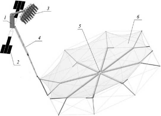
Рис. 1. Конструкция КТР
Fig. 1. The design of the LTR (Large-sized transformable reflector)
algorithms have been developed for the task of spokes deployment, extending them, and providing a given shape of the reflective mesh fabric [6–15]. It is important to study and model the deployment process taking into account the possibility of meters shutdown while minimizing the degradation of the estimation accuracy [16–18].
Consider the implementation of a large-sized space structure using a cable-stayed system to create the necessary shape of the radio-reflecting surface of the reflector (Fig. 1) [10]. A large-sized transformable reflector (LTR) consists of a spacecraft (SC) 1 with deployable elements attached, such as solar panels 2 , irradiating system 3 . To provide a given radiation pattern, the rod 4 extends the reflector 5 to the required focal length. The reflective surface is mesh 6 .
The LTR opening occurs in outer space; thus, it is important to bring the system into working position while minimizing fluctuations, which is achieved by smooth opening and high accuracy of reaching the stops. A large temperature difference, as well as radiation and solar wind, have a perturbing effect on structures, which can lead to distortion of the radiation pattern [11; 12]. Therefore, it is necessary to solve the filtering problems, optimal reflector opening, and correction of observation intervals with an acceptable estimation accuracy, i.e., to investigate the possibility of adjusting the mode of the meters’ active operation.
Mathematical description of the problem
Consider the process of the LTR spoke direct opening. It is necessary to change the position of the
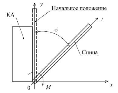
Рис. 2. Разведение спицы рефлектора
spoke to a given angle φ under the force M (Fig. 2). The spoke is rigidly fixed at one end to the SC; the rotation is carried out under the action of an electric motor. Consider the rotation of the spoke in a simplified form, excluding bending vibrations, friction moments created by the stop and the latch. Optimal control of reflector opening taking into account fluctuations is examined in [13; 15].
Fig. 2. The deployment of the reflector spoke
To study the possibilities of optimal automatic adjustment of meters’ active mode of operation, an algorithm was proposed in [17] with optimal correction of control. When applied to the reflector, an appropriate algorithm has been developed [18], which allows saving energy for the meters’ operation.
The mathematical model describing this process has the form x = f (x, u, t) + ^x , under observation
z = a (t, x)[h (x, t) + ^z ], where x – n-dimensional state vector; u – m-dimensional control vector; m ≤ n, ξx, ξz – n- and l- vertors of indignation in the form of white noise with intensities of Bx and Bz respectively; l ≤ n; z – l- vector of measurements; f – h-given continuous vector-function of their arguments of the corresponding dimension, having continuous partial derivative x; t g [10, tf] - variable of continuous time; u g U(t), U(t) - a given area of m-dimentional space.
Let us introduce the time function α( t , τ) which determines the activity of the meters; if α( t , τ) = 1, then at time t the measurement is performed, but if α( t , τ) = 0 – no measurement is performed. Here α( t , τ) = 1 – Δα T ∙1( t – τ 2 j –1 ) + Δα T ∙1( t – τ 2 j ), 1( t – τ 2 j –1 ) = [1( t – τ 1 )1( t – τ 3 ) … 1( t – τ 2 r –1 )] T , 1( t – τ 2 j ) = [1( t – τ 2 )1( t – τ 4 ) … 1( t – τ 2 r )] T , Δα = (Δα 1 Δα 2 … Δα r ) T , Δα j = 1; 1( t – τ 2 j –1 ), 1( t – τ 2 j ) – unit functions;
T 2 j , T 2 j —1 - time points of meters’ turning on and off, j = 1, r .
In this case, the objective functional is minimized, in general, having terminal and integral components, tf
I = M
V f ( x ,x, 1 0 , t f ) + j f 0 ( x , x ,u, t ) dt
t 0
where f 0 , V f – the set positive functions of their arguments with continuous partial derivatives in x , t , function f 0 is also in u . Let us take
V f = V f 1 ( x ’x, t 0 ) + V f 2 ( x , t f ) , V f 1 ( x ,x, 1 0 ) = 0.5 A x o ^ o1 A x 0 ,
V f2 ( x , t f ) = 0.5 A x T pA x f + 0.5 p 0 A x T R ( tf ) A xf + 0.5 p ]T ( t 2 j
\ -2 ---
-T 2 J - 1 ) , J = 1, r , A x 0 = x 0 - x 0 ,
J - 1
Xo = x(tо), xo = x(tо), Axf = x(tf)-Xf, Axf = x(tf)-Xf, p = diag(pi,p2,...,pn), f0 ( x ,x, u, t) = 0.5 Ax T y Ax + 0.5 ( uT k ~2 u + uTk ~2 u 0 ), y = diag (y1, у 2,..., у n ), Ax' = x - x , xf- -the given end value of the vector х, k = diag (ki, к2,..., km); p, p 0, pi, Yi (i = 1,n ), kj (J = l,m ) -
The given coefficients; R 0 , R – matrices of corresponding dimensions.
Here x = (φ ω U) T – state vector. In element by element form, the system is represented as follows:
. . . m ф PE о sin $ fT
Ф = й + £ x , й = U , U = u ,
ωdXcI where φ – spoke angle; ω – spoke angular velocity; ξx – perturbation in the form of a random process with intensity Bx, m^ p En sin 3
M = ф^ 0---U - п ® dXc the effective moment created by a commutatorless machine (equal to the total moment acting on the spoke, excluding friction moments and created by the stop and latch); mф is the number of rotor phases; p is the number of the magnetic field poles pairs; Е0 is the effective value of the electromotive force (EMF); ϑ – mismatch angle (between U and E0, for the engine is within [0, π/2]); ωd is the angular rotation speed of the motor rotor; Xc - synchronous resistance; I is the moment of spoke inertia; U is the supply voltage of the commutatorless machine; u - control.
Consider the spoke as a cylindrical pipe. Let us take it as a one-element construction. The spoke rotation angle is available for measurement. For the problem of spokes deployment, we consider the observation equation in the form (2), where h(x, t) = φ, ξz is a perturbation in the form of a random process with intensity B z .
According to the separation principle [19], control synthesis consists in obtaining an optimal estimate of the state vector and, further, in forming the control itself, assuming that the state vector is precisely known and is equal to the estimate vector x = x, u = u (x, t).
Since the information will not come continuously, it is proposed to optimize the shutdown modes of measuring equipment with the permissible deterioration of the assessment accuracy.
Main result
To develop an optimal control system (1), (2), minimizing criterion (3), it is necessary to have an estimate of the state vector. Let us assume that the evaluation algorithm has the form [16]:
x = f (x, u , t ) + a ( t , t ) Rh T B “1[ z - h ( x, t )],
R = fxR + Rf T - Rh T Bz - 1 hxR + Bx , R ( t 0) = R o. x x xzx x 00
Here x ˆ – n - dimensional evaluation vector. f x = ∂ f /∂ x , h x = ∂ f /∂ x .
Let us introduce an additional control of the moments for turning on and off the measurement device
T = w . (5)
To minimize the cost of the observation time, consider the Krasovsky criterion [19] :
tf
I 1 = I + 0.5 J ( wTk w2 w + w T k W2 № 0 ) dt , k w = diag ( k wi , k w 2,..., k w 2 r ) . (6)
t 0
Assuming f Ф1 = f (x, u, s) + a(s, t)RhXB^[z - h(x, s)], f ф2 = fxR + RfT - a(T, t)RhTB—hxR + Bx.
The original system and the observation equation have the form (1), (2):
x = f ( x , u , t ) + ^ x , x = [ X T Y T ] T , f = [ FT uT ]T , z = a ( t , t)[ h ( x , t ) ■ l z ] .

i = 1, n - matrix columns R and f Ф2 , respectively. Putting Hamiltonian H in the form
H = pT T f Ф 1 + tr [ p T f Ф 2 ] + p T w + p T f + f 0 ( x , u , t )
or
H = p T { f ( x , u , s ) + a ( s , t ) Rh T B —1 [z - h ( x,s )] } + tr { p T [ f x R + Rf T - a ( t , t ) RhT T B ;' h x R + B x ] } + + P T f ( x , u , s ) + p T w + ya ( t , t ) + 0.5( A xTR -1 A x + wTk w w + w T k w w 0 + uTk u — 2 u + u T k - 2u 0) .
Here
n tr pTRfR = E pTRfR , i=1
PR – matrix conjugate to matrix R and composed of columns PRi, pR1i pRni
Then the canonical equations take the form x = f (x, u, t) + q x, Y = u , t = w,
x =
<d P x J
= f Ф 1( x , u , t , R , Bz , t , z ),
R =
' dH
^Pr J
= f Ф 2 ( x , u , t , R , B z , B x , t , z ),
p x = -[d ( P T f ) / d x ] T - f T ,
"gf Ф1' < dx ?
px
—
d tr ( p R f Ф 2) d x
- f0x ,
d H
P r = -Hf I =-a h x B z ( z - h ) P x - P R f x - ft P r +a ( P R R x h x B z h x + h x B z h x RP R ) ,
< d R J 7
p , =-f f T = { - p T Rh X B Z' [ z - h ( x , t ) ] + tr [ Rh B ■ ] } [ ^T .
T T
Here
Ca( t , T ) 1 = -Aa5 ( T - t ) , f о x = y (^) T , f ° x =-у ( Д х ) T ,
Ct
-1 д
P x ( t о ) = R o Д х 0 , P x ( t 0 ) = - R o Д х 0 , P r ( t 0 ) = ^^l Д у TR 0 ^ | = -Д х Д хTR 0 2,
C R
Px ( t f ) = P^ f , P x ( t f ) = P o R ( t f ) ^ f , P r ( t f ) = P o A x f A xT , P t 2 j - 1 ( t f ) = P ( T 2 j- - t 2 j - 1 f*
Pt2 j (tf ) = -Р(Т2 j -Т2 j-1 ) \ ^f = x({f )- xf , Ax = x - X , w(t) = -kWPt(t) , u (t) = -k2 Py (t), Px = ( pX pY )T •
The predictive model in the direct time includes the equations of the dynamics of the reflector spoke deployment and the equation of the Kalman filter with a constant mode of meters operation. Next, the boundary values of the conjugated variables are calculated. When integrating in the reverse time, equations for conjugated variables are added to the forecast equations. After finding the values of the conjugated variables at the moment, control is calculated. Further, the initial control system integrates one step forward. When t < t f calculations are repeated from the current position. With t > t f calculations are completed.
During calculations, the switching sequence т i , i = 1, r remains unchanged. When adjacent values of switching times approach the minimum value (τ i +1 – τ i ) < ε , τ i +1 = τ i is taken and the number of all switchings in the structure (r) decreases by one: (r – 1), where ε > 0 is a given small value.
Here
& + a ( t , t ) Bz 1 R 11 ( z - x * )
f
ф1
т ф pE 0 sin 9- , _
-----—— U + a ( t , t ) Bz R12 ( z - x i )
®dXcI u + a(t,t)BZ-1 R13 (z - x1)
f l2 = 2 R 12 -a ( t , t ) B - R 121 + B x ,
., т ф pE 0 sin9 . .
f 12 = R 22 + 7Г~Г R 13 - a ( t , t) B z R 11 R 12 ,
® dXcI fl2 = R23 -a(t,T)Bz'R11R13 , m^pEp. sin9 , x 1 i fl2 = 2 ф ° R23 -a(t,t)B- R122 ,
® d X c 1
m^pEo sin 9 , . .
f 2l2 = ф 0 T R 33 -a ( t , t ) B - 1 R 21 R 13 ,
® d X c 1
f ф2 - -a (t -IP^R2 ф22 — ф22 ф22 - /~ф2 ф22 - ф22
J 33 = a ( t , Т ) B z R 13 , J 21 = f 12 , f 31 = f 13 , J 32 = J 23 •
The spoke is driven by a Phytron commutatorless motor of the phySPACE series [20] with the accuracy of 3-5% for 1.8º. A LIR-MA208 encoder [21] with the accuracy of ±1º is used as an angular position sensor. But since the rotation of the spoke is considered in a simplified form excluding bending vibrations, it is necessary to increase the intensity of measurement errors B .
It is required to move the spoke from the initial position x (0) = (0 0 0) T to the final position x ( t f ) = (π/2 0 0) T with no overshoot in the turn angle φ in the time t f = 60 s in the presence of external disturbances ξx and measurement noise ξz.
Modeling
Assuming the opening time of the spoke t f = 60 s. The number of the rotor phases m э = 2, the number of the magnetic field poles pairs p = 2, the effective value of the EMF on the stator winding E 0 = 2.5 V, the synchronous resistance Xc = 22∙10-3 Ohm, the mismatch angle between the field of the rotor and the stator ϑ = π /10 at any load, ω p =247 rad/s. We consider a spoke of length a = 9.75 m , a mass (of all nested links) m = 32 kg , a cross section in the form of a ring with an outer radius R = 0.26 m and an inner radius r = 0.25 m . Moment of inertia I = mR 2/2+ ma 2/3 = 1015.4 kg·m2.
In calculations, the noises ξx and ξz were assumed to be white with intensities B x =0.00279, B z =0.0156, respectively.
Figure 3 shows the simulation results for continuous measurements: dependency graphs φ(t), ω(t) . In this case, the estimation errors took the values: R 11 ( t f ) = 0.00683, R 22 ( t f ) = 0.00004. It can be seen that it was possible to solve the problem posed, i.e., to open the spoke from the initial position to a given angle π/2.
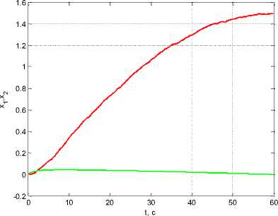
Рис. 3. Графики х 1 ( t ) = ф ( t ) , x 2 ( t ) = го ( t )
Fig. 3. Graphs x 1 ( t ) = ф ( t ) , x 2 ( t ) = ® ( t )
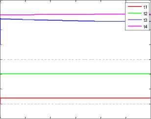
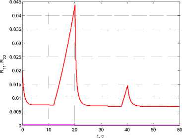
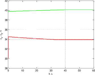
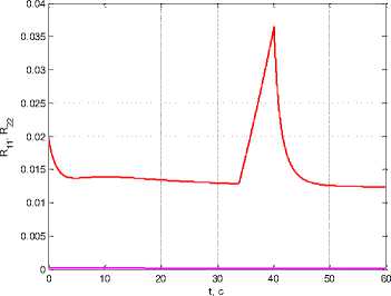
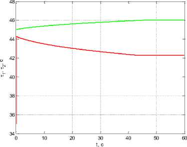
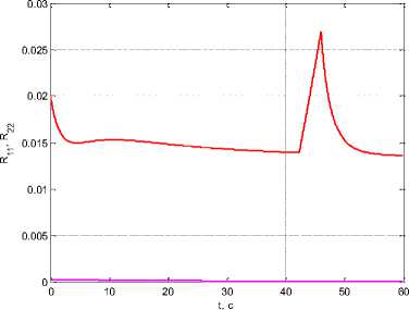
Further, calculations were carried out applying the above algorithm with the observation intervals corrections. Initially, 2 measurement shutdown intervals were taken: from the moment τ1 = 10 s to τ2 = 20 s and from τ3 = 30 s to τ4 = 40 s. With the values of the weight coefficients in the criterion (3) ρ0 = 10-10, в = 10-2, kw 1 = 240-12, kw2 = 2^10-8, kwз = 4, kw4 = 1 in fig.4a shows graphs тi(t), i = 1,4, and in fig. 4b – diagonal elements of the covariance
matrix R11(t), R22(t). As a result, the initial measurement shutdown intervals Δτ1(t0) = τ2(t0) – τ1(t0) = 10 s, τ2(t0) = τ4(t0) – τ3(t0) = 10 s passed at τ1(tf) = 11.998 s ,
T 2 (t f ) = 20.134 s, T 3 (t f ) = 37.863 s, T 4 (t f ) = 40.215 s in Ат 1 ( t f ) = t 2 ( t f ) -т 1 ( t f ) = 8.136 s,
At2 (tf ) = t4 (tf ) — T3 (tf) = 2.352 s, i.e. the sum = 20 s decreased to At( tf ) = Ат1 (tf ) + At2 (tf ) =
10,488s, i.e. there was a narrowing of the intervals for shutdown measurements.
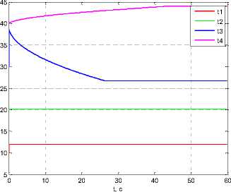
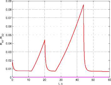
With an increase in the coefficient β, the interval for shutdown measurements should increase.
For example, when β = 1 we get τ 1 (t f ) = 11.978 s, τ 2 (t f ) = 20.126 s, τ 3 (t f ) = 26.648 s, τ 4 (t f ) = 44.034 s and AT i (t ± ) = 8.148 s, AT 2 (t f ) = 17.386 s, i.e. the sum At ( t 0 ) = A^ ( t 0 ) +Дт2 ( t 0 ) = 20 s increased to Дт ( tj. ) = Д^ ( t y ) + Дт2 ( t y ) = 25.534 s. Fig. 5 shows the corresponding graphs.
0 10 20 30 40 50 60
t, c
а
б
Рис. 4. Графики: а - т ( t ) , i = 1,4 ; б - R j j ( t ) , R 22 ( t ) при 2 интервалах отключения измерений и в = 10 2
Fig. 4. Graphs: а - т, ( t ) , i = 1,4 ; b - Rt j ( t ) , R22 ( t ) at 2 measurement shutdown intervals and в = 10 2
а
б
Рис. 5. Графики: а - т i ( t ) , i = 1,4 ; б - R n ( t ) , R 22 ( t ) при увеличении коэффициента в
Fig. 5. Graphs: а - т i ( t ) , i = 1,4 ; b - R 11 ( t ) , R 22 ( t ) when increasing the coefficient в
Consider now one measurement shutdown interval: τ 1 ( t 0 ) = 30 s, τ 2 ( t 0 ) = 40 s, At ( t 0 ) = т ( t 0 ) — т ( t 0) = 10 s. For the values of the coefficients: p 0 =10-6, P=10-2, k w 1 =10, k w 2 =5 we obtain τ 1 ( t f ) = 33.91 s, τ 2 ( t f ) = 40.122 s и Δτ( t f ) = 6.212 s, i.e. narrowing the interval (fig. 6).
а
б
Рис. 6. Графики: а - тД t ) , i = 1,2 ; б - R j j ( t ) , R 22 ( t ) при 1 интервале отключения измерений и в = 10 2
Fig. 6. Graphs: a - тД t ) , i = 1,2 ; b - R j Д t ) , R 22 ( t ) at 1 measurement shutdown interval and в = 10 2
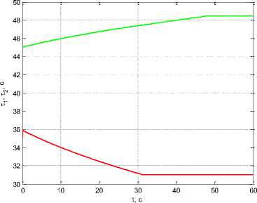
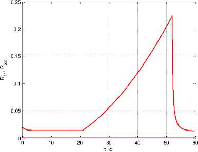
When ρ 0 = 10–6, β = 1, k w 1 = 10, k w 2 = 5 we obtain τ 1 ( t f ) = 20.953 s, τ 2 ( t f ) = 52.05 s and Δτ( t f ) = 31.097 s, i. е. an increase in the coefficient β leads to an extension of the measurement shutdown interval (Fig. 7).
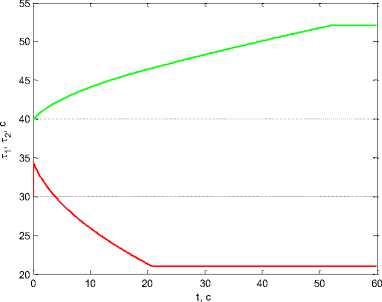
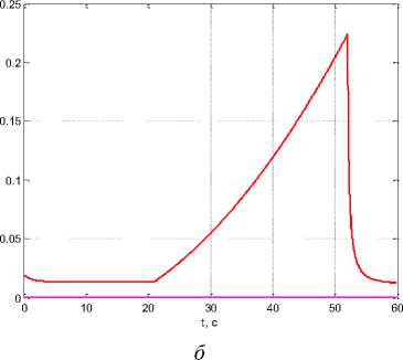
Рис. 7. Графики: а - тД t ) , i = 1,2 ; б - R j Д t ) , R 22 ( t ) при 1 интервале отключения измерений и при увеличении коэффициента β
Fig. 7. Graphics: a - тД t ) , i = 1,2 ; b - R j Д t ) , R 22 ( t ) at 1 measurement shutdown interval when increasing the coefficient β
Now assuming t i ( 1 0 ) = 35 s, T 2 ( 1 0 ) = 45 s, Ат ( t 0 ) = т2 ( t 0 ) -тД t 0) = 10 s. Under coefficient values ρ 0 = 10–5, β = 10–2, k w 1 = 10, k w 2 = 5 we obtain τ 1 ( t f ) = 42.311 s, τ 2 ( t f ) = 46.012 s and Δτ( t f ) = 3.701 s, i. е. narrowing the interval (fig. 8). In this case R 11 ( t f ) = 0.0136, R 22 ( t f ) = 0.0000423.
а б
Рис. 8. Графики: а - тгД t ) , i = 1,2 ; б - R 11 ( t ) , R 22 ( t ) при изменении начальных значений т i ( 1 0)
Fig. 8. Graphs: a - т i ( t ) , i = 1,2 ; b - R 11 ( t ) , R 22 ( t ) when changing the initial values T i ( 1 0)
Under coefficient values ρ 0 = 10–6, β = 0.2, k w 1 = 10, k w 2 = 5 we obtain τ 1 ( t f ) = 31.051 s, τ 2 ( t f ) = 48.47 s and Δτ( t f ) = 17.419 s, i. е. decreasing the coefficient ρ 0 while increasing β lead to the observation shutdown interval extension (fig. 9). At this point R 11 ( t f ) = 0.0137, R 22 ( t f ) = 0.0000423.
As can be seen from the calculation results, the algorithm with optimal correction of observation intervals can be actively used in solving the problem of saving energy costs for measurements with the acceptable estimation accuracy. It is assumed that the sequence of switching moments in the meters’ operation remains ordered along the time scale. The algorithm ensures the merging of approaching switching moments excluding the corresponding area. The results of numerical modeling demonstrate the possibility of reducing the operating time of the measuring instrument with acceptable estimation accuracy.
а
Рис. 9. Графики: а - т, ( t ) , i = 1,2 ; б - R j j( t ) , R 22( t ) при уменьшении коэффициента p0 и увеличении коэффициента β
б
Fig. 9. Graphics: a - t, ( t ) , i = 1,2 ; b - R j j( t ) , R 22 ( t ) when decreasing the coefficient p0 and increasing the coefficient β
At the stage of the control system design, depending on the type and intensity of random disturbances and the requirements for permissible energy costs, studies are carried out on the type of observation structure, the establishment of criterion weights that ensure automatic determination of the measurement shutdown interval. Depending on the obtained values of the criterion weight coefficients, it is possible to correct the operating mode of the measuring instrument. When the sensors are turned off, energy for their operation and data transmission is not expended.
Further refinement of the boundaries of the observation shutdown intervals can be performed autonomously on board the system.
Conclusion
In this paper, we have obtained a solution to the problem of optimizing control processes using the sequential optimization algorithm [14] and observation using the algorithm presented above with correction of the observations structure [17; 18]. As a result of the work done, the solution of the problem of optimal control of the stochastic model of the LTP spoke deployment was confirmed by incomplete data using the separation principle. The use of the sequential optimization algorithm with the data obtained, estimated using the Kalman filter along with correction of the measurement shutdown intervals, helped to solve the problem. The results of the work - reducing the time of switching on the measuring instruments with acceptable accuracy - were obtained by numerical modeling. Interval shutdown of measurements allows reducing energy consumption for sensor power supply and measurement processing. In the future, to improve the presented algorithm, it is also possible to apply the joint solution of navigation and control problems as a hierarchical differential game instead of the separation principle [22].
The presented studies were reported at the XXVI International Scientific Conference "System Analysis, Control and Navigation" [17;18].
Acknowledgment. The reported study was funded by RFBR according to the research project No 20-08-00646a.
References Optimal control of deployment of the spoke of a transformable reflector in the presence of disturbances
- Puig L., Barton A., Rando N. A review on large deployable structures for astrophysics missions. Acta Astronautica. 2019, Vol. 67(1), P. 12–26.
- Polyanskij I. S., Arhipov N. S., Misyurin S. Yu. [On the solution of the problem of optimal control of an adaptive multi-beam reflector antenna]. Avtomat. i telemekh. 2019, No. 1, P. 83–100 (In Russ.).
- Vlasov A. Yu., Amel'chenko N. A., Pasechnik K. A., Titov M. A., Serzhantova M. V. [Static and modal analysis of the power construction of the precision large-sized antenna reflector from polymer composite materials]. Siberian Journal of Science and Technology. 2017, No. 4, P. 897–901 (In Russ.).
- Nie R., He B., Zhang L. Deployment dynamics modeling and analysis for mesh reflector antennas considering the motion feasibility. Nonlinear Dyn. 2018, Vol. 91, P. 549–564.
- Thomson M. W. The AstroMesh Deployable Reflector. IUTAM-IASS Symposium on Deployable Structures: Theory and Applications, 2000, P. 435–446.
- Li P., Liu C., Tian Q., Hu H., Song Y. Dynamics of a deployable mesh reflector of satellite antenna: form finding and modal analysis. J Comput. Nonlinear Dyn. 2016, Vol. 11(4), P. 549–564.
- Reznik S. V., Chubanov D. E. [Large-sized transformable space antenna reflector made оf composite materials dynamic modeling process]. RUDN Journal of Engineering Researches. 2018, Vol. 19(4), P. 411–425 (In Russ.).
- Bakulin V. N., Borzyh S. V. [Modeling the dynamics of the process of deployment large-sized transformable space structures]. Izvestiya vysshih uchebnyh zavedenij. Aviacionnaya tekhnika. 2020, No. 4, P. 50–56 (In Russ.).
- Berns V. A., Levin V. E., Krasnorutsky D. A., Marinin D. A., Zhukov E. P., Malenkova V. V., Lakiza P. A. [Development of a calculation and experimental method for modal analysis of large transformable space structures]. Spacecrafts & Technologies, 2018, Vol. 2, No. 3, P. 125–133 (In Russ.).
- Huang H., Cheng Q., Zheng L., Yang Y. Development for petal-type deployable solid-surface reflector by uniaxial rotation mechanism. Acta Astronautica. 2021, No. 178, P. 511–521.
- Ishkov V. N. [Solar geoeffective phenomena: Action on the near-earth outer space and the possibility of the forecast]. Slozhnye sistemy. 2012, No. 4 (5), P. 21–41 (In Russ.).
- Mihalyaev B. B., Derteev S. B., Lagaev I. Yu., Osmonov T. T. [Vliyanie solnechnoj aktivnosti na magnitosferu Zemli]. Aktual'nye problemy sovremennoj fiziki i matematiki. trudy. 2017, P. 92–97 (In Russ.).
- Kabanov S. A., Mitin F. V. Optimization of the Processes of Deploymentand Shape Generationfor a Transformable Space-Based Reflector. Journal of Computer and Systems Sciences International, 2021, Vol. 60, No. 2, P. 283–302.
- Kabanov S. A., Kabanov D. S. Deployment the Spoke of a Large-Sized Transformable Refl ector Using a Sequential Optimization Algorithm. Mekhatronika, Avtomatizatsiya, Upravlenie. 2021; Vol. 22(8), P. 433–441 (In Russ.).
- Kabanov S. A., Kabanov D. S., Nikulin E. N., Mitin F. V. Optimal control of deployment of the spoke of a transformable reflector in the presence of disturbance. Siberian Aerospace Journal. 2021, Vol. 22, No. 4, P. 649–659.
- Malyshev V. V., Krasil'shchikov M. N., Karlov V. I. Optimizaciya nablyudeniya i upravleniya letatel'nyh apparatov [Optimization of surveillance and control of aircraft]. Moscow, Mashinostroenie Publ., 1989, 312 p. (In Russ.).
- Kabanov D. S. Optimal control of a stochastic system with the correction of observation intervals. Sistemnyy analiz, upravlenie i navigaciya. Moscow, MAI Publ., 2022, P. 119–120.
- Kabanov S. A., Kabanov D. S., Nikulin E. N., Mitin F. V. Optimal control of deployment of the spoke of a transformable reflector in the presence of disturbance. Sistemnye analiz, upravlenie i navigaciya. Moscow, MAI Publ., 2022, P. 117–118.
- Spravochnik po teorii avtomaticheskogo upravleniya. [Handbook on the theory of automatic control.]. Ed. by A. A. Krasovskiy. Moscow, Nauka Publ., 1987, 712 p. (In Russ.).
- Mikroprivod. Seriya phySPACE dlja raboty v kosmose, diametr 19–125 mm [Microdrive. phySPACE Space Series, 19–125 mm diameter]. Available at: http://www.microprivod.ru/catalog/ phytron/seriya-vssspase-dlya-rabotyi-v-kosmose,diametr-19-125-mm.html (accessed: 31 August 2022) (In Russ.).
- LIR-MA208E. Absoljutnyy uglovoy yenkoder [LIR-MA208E. Absolute rotary encoder]. Available at: https://skbis.ru/catalog/rotary/absolute-rotary-encoders/lir-ma208e (accessed: 31 August 2022) (In Russ.).
- Kabanov S. A. Optimizaciya dinamiki sistem pri deystvii vozmushcheniy [Optimization of the dynamics of systems under the action of disturbances]. Moscow, Fizmatlit Publ., 2008, 200 p.
