Optimization of new types of electromechanical converters for mechanisms with fan-type loads

Author: Savosteenko Nikita V., Semenova Kseniya D., Khriukin Dmitry Yu., Maksimov Nikita M.
Journal: Вестник Южно-Уральского государственного университета. Серия: Энергетика @vestnik-susu-power
Section: Электромеханические комплексы и системы
Article in issue: 1 т.22, 2022.
Free access
The article considers the main requirements for pumping stations, in particular, for methods of regulating the water supply at the first lift pump unit. A description of the pumping unit and equipment is provided. The article provides a comparison of the types of the main drive units of pumping stations. It also provides a rationale for the choice of electric drive system between classical asynchronous and synchronous electric drives, as well as a system with a field regulated reluctance machine (FRRM) with a comparison of energy indicators. A description and substantiation of the control system work are also given. The articles provide the technical characteristics of the motor parameters and the daily flow rate of the station fluid. The optimal method for regulating the power supply system was chosen based on research. A mathematical model of the device which implements the chosen control method is presented. The results of mathematical modeling are presented in the graphs. A graph of the transient process is given in the case of changing speeds depending on the required fluid supply. Conclusions about the efficiency of the system are drawn and further action plans are outlined.
Pump, pumping units, electric motor, control system design, field regulated reluctance machine
Short address: https://sciup.org/147237522
IDR: 147237522 | UDC: 621.3
Оптимизация новых типов электромеханических преобразователей для механизмов с вентиляторным характером нагрузки
В статье рассмотрены основные требования, предъявляемые к насосным станциям, в частности к способам регулирования подачи воды на насосной станции первого подъема. Дано описание насосного агрегата и рассматриваемого оборудования. Приведено сравнение видов основных приводных агрегатов насосных станций с обоснованием выбора системы электропривода между классическим асинхронным и синхронным электроприводами и системы с синхронной реактивной машиной независимого возбуждения со сравнением энергетических показателей. Приведено описание и обоснована работа системы регулирования. Приведены технические характеристики параметров двигателя и суточного расхода жидкости станции. На основании проведенных исследований был выбран оптимальный метод регулирования системы питания. Приведена математическая модель устройства, реализующего выбранный метод регулирования. Полученные результаты математического моделирования представлены на графиках. Приведен график переходного процесса при изменении скоростей в зависимости от необходимой подачи жидкости. Сделаны выводы о работоспособности системы и намечены дальнейшие планы действий.
Text of the scientific article Optimization of new types of electromechanical converters for mechanisms with fan-type loads
Дмитрий Юрьевич Хрюкин, , 0000-0001-7854-4989
The technological process of the enterprise sets the operating modes of the pumping units. If the pumping unit operates without intermediate tanks, i.e. directly into the network, the supply is equal to the water consumption. This is provided that there are no leaks and non-productive costs, which in reality can be 15–20% of the total supply. For this reason, the actual supply is slightly higher than water consumption [1].
The process of artificially changing the characteristics of a pipeline or pump, in order to ensure that the pump operates at the required operating point is called pump regulation. In addition, maintaining the required pressure in the network leads to the preservation of the material and energy balance of the “pump – network” system. This also requires regulation of changes in characteristics, the pump impeller speed, the geometry of the pump flow channels and the kinematics of the flow at the impeller inlet [2].
Theoretical part
Serious requirements are imposed on the drive motors of pumping units: from easy control automation and low operating costs, to the need to start the motor under load and countermotion rotation. These parameters are determined by the load characteristic of the pump. Improved operating conditions of power systems where powerful pumping stations are used, require frequent restarting. This places increased demands on the structures of the stator winding and the starting winding of the electric motor [3]. Heating determines the duration of the required pause between starts and the permissible number of starts for the period under consideration.
The pump impeller speed can be changed by a variable speed motor. However, when the pump impeller speed changes, all operating parameters and characteristics of the pump unit change directly. At low speeds, less than 0.1 n nom , the unambiguity of the relationship between head and flow is breached. Due to this, the operating speed range of the pumping units must lie within:
The automation control system of the pump unit depends directly on the technological mode of operation and provides all the operating conditions for uninterrupted operation. An important role is played by the load schedule parameter which must be maintained within the specified limits.
The most common requirement for pump units of urban and regional networks is the continuous replenishment of feed water. The feeding unit pumps water by increasing its pressure, taking into account the resistance of the water. This is achieved by pumps connected in series: one of these is the main feed pump, and the other is a booster (upstream). This is due to one of the main conditions that the water pressure at the inlet to the pumps of the second lift (main feed) should slightly exceed the saturation pressure at the water temperature in front of the pumps, in order to prevent cavitation. Most often, booster pumps are based on an unregulated electric drive. This allows emergency cavitation mode to be prevented only in nominal operating modes [4].
Cavitation reduces the efficiency, head and performance of the pump. The change in the structural flow by cavitation is qualitative and leads to changes in the operating modes of hydraulic machines. If a cavitation zone occurs on surfaces designed to control fluid flows, then both the effective flow shape and the flow path change. This is accompanied by additional losses. It can also lead to a decrease in flow, causing a sharp drop in the efficiency of any hydraulic machine. The emergence of a cavitation zone causes instability and manifests itself in the appearance of secondary flows of liquid and pressure pulsations in flows with dynamic effects on the guiding surfaces – vibrations. The most dangerous and destructive consequences of cavitation are manifested in the appearance of cavitation bubbles at the surface of the blades. This is accompanied by the destruction of the surface of the parts of hydraulic machines [5]. The surfaces of the parts become rough and pitted, which contributes to the rapid abrasion of parts by inclusions contained in the liquid. Long-term operation of the pump in the presence of even minor cavitation phenomena is completely unacceptable [6].
However, the greatest danger is the operation of the pump in an unstable mode (surge). This mode arises due to high back pressure at the pump unit outlet. For example, the pump unit outlet is always con- nected to a heat boiler, where the water is heated to boiling, greatly increasing the pressure in the boiler. Therefore, the back pressure at the outlet of the pump unit increases until the feed pump. If this is operating in nominal mode, it will be unable to create sufficient pressure for water to enter the boiler. In this case, water will be thrown back into the feed pump which will lead to instantaneous failure of the blades and the pump as a whole [7].
Electrical machines overview
Synchronous machines are used to drive powerful pumps under continuous operating conditions. The working rotor winding is powered by an exciter which can be either a DC generator or a thyristor exciter. They are usually located separately from the electric motor. A synchronous electric motor can operate with a power factor close to or equal to unity. This in turn improves the power factor of the network and saves some electricity. However, a significant disadvantage of synchronous motors is the lack of torque on the shaft at start-up and, accordingly, the need to spin them up to synchronous or close to synchronous speed.
Asynchronous squirrel-cage motors, in turn, are widely used in small pumping units up to 100 kW. This is due to their simplicity and relatively low cost. Due to the direct start of the motors, there is no need for additional devices, and, therefore, the control system is much simpler. However, with such a start, the multiplicity of the starting current can reach values 5–7 times higher than the nominal value. This causes a voltage drop in the network, which can have an adverse effect on other consumers [8].
Since the mid-20th century, one of the most promising electric drives is a variant with synchronous reluctance machines (SRM). The advantages are ob- vious – simplicity of design, non-contact, high shaft rigidity. However, the active introduction of an electric drive with a SRM is hampered by the low specific indicators of reactive machines, and the existence of a torque limit in terms of overload capacity as in an asynchronous electric drive. One option which resolves a number of problems described above is an electric drive with an FRRM. Just like in a DC drive, there is no need to pass a sinusoidal current through the stator windings. Unlike IM machines with sinusoidal excitation, the harmonic components of the excitation field interact in an electric drive with FRRM and create useful torque. The reason for this phenomenon is the constancy of the moment angle. It is estimated that higher harmonics increase the developed torque by about 23% [5].
Table 1 presents the comparative data of various electric motors. According to this data, a field regulated reluctance machine was chosen in view of many positive aspects. Fig. 1 shows the comparison of energy parameters, calculated by the strategy, described in [7, 8] and Table 2 shows the results of calculation.
The main electrical losses in the stator winding are calculated by
P Ei = m^ I l • т 1 , (1)
where т1 is an active resistance of the stator winding;
I ^ - stator current;
m is the number of phases.
Main losses in stator steel can be calculated as:
P ' = P l/50 • g^) 1'3 X
x (kDA •Bl^ma + kDZ • Bl • mzi), (2)
where p 1/50 - specific losses at an induction of 1 T and a frequency of magnetization reversal / 1 = 50 Hz;
kDA and kDZ are coefficients that take into account the increase in losses in steel due to technological reasons;
Table 1
Differences and similarities of FRRM with other electric motors
|
The electric machine to which the FRRM was compared |
Distinction |
Similar signs |
|
|
Feature |
Where it is used |
||
|
DC motor |
No commutator, windless salient pole rotor, control system with power sources |
Trapezoidal field shape at no load and distorted shape due to armature response under load |
Electromagnetic calculation, mathematical model of a machine, synthesis of control systems |
|
IM motor |
Rotor without winding, stator winding with full pitch, rectangular current waveform, control system with power sources |
Multiphase stator winding, stator magnetic system |
Electromagnetic calculation, machine manufacturing technology |
|
Synchronous Reluctance Machine |
Simple rotor with small L d / L q , special laws of stator current control, rectangular current waveform |
Multiphase winding on stator, salient pole, winding-free rotor |
Machine manufacturing technology |
|
Synchronous Motor |
Non-sinusoidal field shape, windless massive rotor |
Stator magnetic system, salient pole rotor |
Electromagnetic calculation, mathematical model, manufacturing technology |
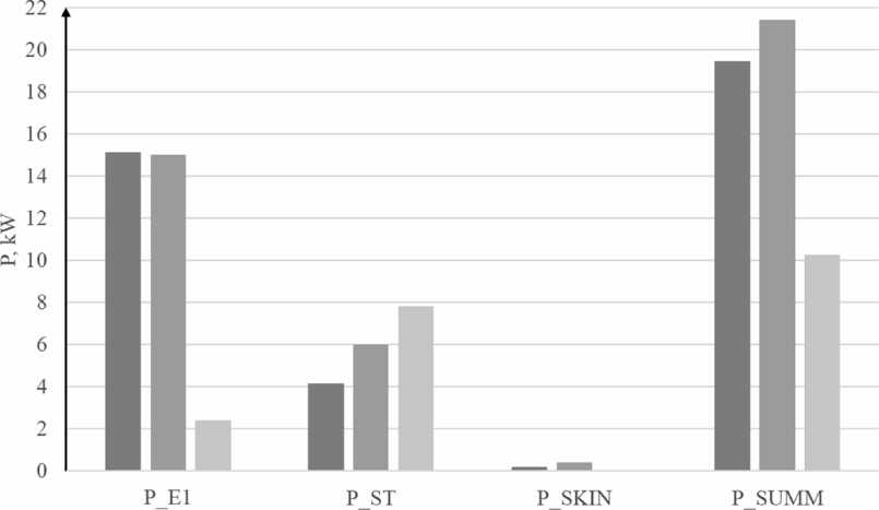
■ IM 1SM I FRRM
Fig. 1. Diagram of energy parameters comparison
Table 2
Calculated values
|
Parameter |
IM |
SM |
FRRM |
Unit |
|
РE1 |
15.11 |
15 |
2.415 |
kW |
|
Рst |
4.14 |
6 |
7.8303 |
kW |
|
Рskin |
0.2 |
0.4 |
0.01484 |
kW |
|
Рsum |
19.45 |
21.4 |
10.26014 |
kW |
|
Efficiency |
85 |
88 |
91 |
% |
B0=B , • (k , - 1);
Bs - induction in the gap;
ma - number of phases in the armature zone.
Rotor skin losses calculated as:
Pskln = 0,5 • 2 • P • ap • T ‘Is ‘ko‘ (7^) X x (Bo • tzl • 103)2 • 10-3, (3)
where ls - calculated length of the magnetic circuit;
k o = 23.3 for massive rotor poles;
-
n is the rotor speed, rpm;
-
ap = 0,5 - pole arc;
-
τ – pole division;
-
tzl - tooth pitch of the stator.
Total losses:
-
P x = PE l +P st +P skin . (4)
FRRM and its control system design
The parameters of the feeding pump station and the drive motor installed on one of the units are used in mathematical modeling [9, 10]. This station faces frequent equipment failures due to cavitation overloads. The equipment is old and needs to be refurbished. Failure of equipment and frequent failures in the operation of pumping units required modernization [11].
The parameters of the pumping station were obtained from the characteristics of daily water consumption: supply control range [12, 13] Q min … Q max = = 130…170 m3/h.
The parameters of the new pumping station and the parameters of the drive motor parameters on it are presented in Table 3.
Pump station and motor parameters
Table 3
|
Feed regulation range Q min… Q max, m3/h |
Power, kW |
n , Rpm |
Current at 380 V, А |
Effectiveness, % |
Power factor |
^ ST ^ nom |
^ max ^ nom |
|
130…170 |
75 |
3000 |
134.6 |
93 |
0.90 |
7.0 |
2.6 |
Mathematical modeling of the FRRM was carried out according to [14]. Since this type of drive is not typical, the design of the FRRM was also carried out in the ANSYS software environment, in order to confirm the mathematical justification. The design of the FRRM was carried out in the ANSYS software environment. The FRRM electric motor was developed in the ANSYS Maxwell software product (Fig. 2). The booster pump control system was simulated in the ANSYS Electronics Desktop software (Fig. 3, 4).
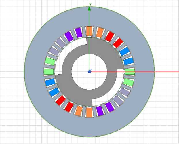
Fig. 2. Designed FRRM

Fig. 3. Model of the control system FRRM pump drive
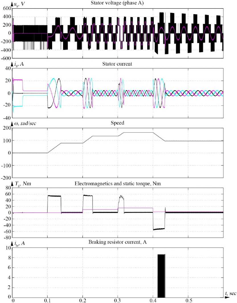
Fig. 4. Transient characteristics of the control system FRRM pump drive
Results
The paper presents the rationale for the use of a field regulated reluctance machine as a pump feeding drive. Based on the results obtained, we recommended the use of FRRM in the pump unit systems. This is due to its more successful energy parameters, which extend the regulated liquid flow rate and also increase of the accuracy of the pump unit electric drive. The surge mode is eliminated by installing the pump electric drive and regulating its speed as a function of torque.
References Optimization of new types of electromechanical converters for mechanisms with fan-type loads
- Leznov B.S. Energosberezheniye i reguliruyemyy elektroprivod v nasosno-nagnetatel'nykh ustanovkakh [Energy saving and variable electric drive in pumping and injection installations]. Moscow: Energoatomizdat Publ.; 2006. 358 p. (In Russ.)
- Karolin V.Ya., Minayev A.V. Nasosy i nasosnyye stantsii [Pumps and pumping stations]. Moscow: Stroyizdat Publ., 1987. 315 p. (In Russ.)
- Leznov B.S. Energosberezheniye nasosnykh agregatov [Saving energy in pumping units]. Moscow: Energoatomizdat Publ., 1991. 144 p. (In Russ.)
- Ryzhkin V.Ya. Teplovyye elektrostantsii: ucheb. dlya vuzov [Power Plants: Textbook for Universities]. Moscow: Energoatomizdat Publ., 1987. 328 p. (In Russ.)
- Grigoryev M.A. Extreme indexes of electric drive with field regulated reluctance machine and with other electrical machine. Bulletin of the South Ural State University. Ser. Power Engineering. 2009;12(34):51-55. (In Russ.)
- Usynin Yu.S. Sistemy upravleniya elektroprivodom: ucheb. [Electric drive control systems. Textbook]. Chelyabinsk: SUSU Publ.; 2004. 328 p. (In Russ.)
- Gorozhankin AN, Kushnarev VA, Gryzlov AA. Assessment of electromechanical conversion efficiency in synchronous reluctance machines. Russ Electr Eng. 2021;92(5):233-7. DOI: 10.3103/S1068371221050047
- Protopopov A., Belov N., Kalugina M., Mukhlaeva A. Research of dependence centrifugal pump efficiency of impeller slit seal design parameters. IOP conference series: Materials science and engineering; 2020. DOI: 10.1088/1757-899X/963/1/012003
- Beygi S., Tabesh M., Liu S. Multi-Objective Optimization Model for Design and Operation of Water Transmission Systems Using a Power Resilience Index for Assessing Hydraulic Reliability. Water Resources Management. 2019;33(10):3433-3447. DOI: 10.1007/s11269-019-02311-x
- Candelieri A, Perego R., Archetti F. Bayesian optimization of pump operations in water distribution system. Journal of Global Optimization. 2018;71(1):213-235. DOI: 10.1007/s10898-018-0641-2
- Agathokleous A., Christodoulou C.A., Christodoulou S.E. Influence of intermittent water supply operations on the vulnerability of water distribution networks. Journal of Hydroinformatics. 2017;19(6):838-852. DOI: 10.2166/hydro.2017.133
- Usynin Yu.S., Bychkov A.E., Funk T.A. et al. Sistema upravleniya elektroprivodom nasosnoy ustanovki i sposob raboty sistemy [The control system of the electric drive of the pumping unit and the way of the system operation]. Patent RU 2687175, 2019.
- Semenova K.D., Savosteenko N.V., Maksimov N.M., Belov N.A. Mathematical modelling of pump station. Paper presented at the IOP Conference Series: Materials Science and Engineering. 2020;919(6). DOI: 10.1088/1757-899x/919/6/062063
- Semenova K.D., Chenfei, W., Xiaoli, L., Savosteenko N.V., Savosteenko G.A. The Analysis of Pump Unit Equipment. In: Proceedings of the 2021 IEEE Conference of Russian Young Researchers in Electrical and Electronic Engineering, ElConRus 2021; 2021. P. 1073-1076. DOI: 10.1109/elconrus51938.2021.9396355
