Optimization the position of the spacecraft instrument panel mounting points based on modal analysis

Author: Kolga V. V., Lykum A. I., Marchuk M. E., Filipson G. U.
Journal: Siberian Aerospace Journal @vestnik-sibsau-en
Section: Aviation and spacecraft engineering
Article in issue: 2 vol.22, 2021.
Free access
The paper presents optimization of the location of interface points of the spacecraft instrument panel using modal analysis, as well as a quasi-static calculation of the panel under study, confirming effective-ness of proposed changes in the panel design. The instrument panel is a three-layer honeycomb structure consisting of two aluminum plates and a honeycomb filler. Cellular panels have a number of advantages: a small weight of the structure, high rigidity, specific strength. Using finite element modeling, the range of natural frequencies and vibration patterns of the instrument panel was determined, which made it possible to determine optimal location of the panel fixing points to the spacecraft body to increase the lower limit of natural frequency range and increase its carrying capacity.
Instrument panel, optimization, mode, natural frequencies, interface points.
Short address: https://sciup.org/148321808
IDR: 148321808 | UDC: 629.7.062 | DOI: 10.31772/2712-8970-2021-22-2-328-338
Text of the scientific article Optimization the position of the spacecraft instrument panel mounting points based on modal analysis
Engeneering of modern spacecraft (SC) is characterized by a high density of placement of instruments on panels to reduce the size of the spacecraft.
Determination of fixing points of instruments on the panel and fixing points of the on-board panel to spacecraft power elements affects the range of natural frequencies of the spacecraft and its individual elements.
To fulfill the requirements for ensuring spacecraft carrying capacity, its parameters for comparing characteristics with an allowable range, determined by technical task requirements, are required.
In the process of engeneering rocket and space technology, in general, and spacecraft, in particular, one of the stages in the analysis of bearing capacity of a structure is to simulate its natural frequencies and the frequencies of its individual elements, for example, instrument panel, in order to ensure the requirements for values of the lower limit of investigated frequency range [1–6].
Research objective
Let us consider an instrument panel, which is part of the Ka-band antenna as a power element, for installing responder equipment on it. The design is a three-layer honeycomb package, consisting of two loadbearing elements in a form of aluminum plates, between which cells of hexagonal aluminum foil are located (Fig. 1). The total panel thickness is 22 mm.
Рис. 1. Модель приборной панели космического аппарата
Fig. 1. Spacecraft instrument panel model
The panel experiences main loads during its transportation and in the spacecraft launching section. Based on the requirements of strength standards for similar devices, when engeneering, it is necessary to ensure a minimum natural frequency of at least 150 Hz.
In many cases, the conclusion about bearing capacity of honeycomb structures is accepted as a result of processing the results of field tests, which are quite expensive and intensive. Therefore, assessment of design parameters based on the results of numerical modeling simulating the conditions of full-scale tests is an urgent task to reduce the cost of engeneering process [7].
To carry out a parametric analysis of spacecraft instrument panel, we identified the following tasks:
-
- to form a finite element model of instrument panel;
-
- to carry out its modal analysis and compare the range of natural frequencies with the permissible lower value;
-
- to assess bearing capacity of instrument panel from the action of quasi-static loads;
-
- to study the influence of location of the panel fixing points on changing natural frequency range of the panel and increasing its bearing capacity.
The finite element discretization of instrument panel surface is shown in Fig. 2.
Рис. 2. Конечно-элементная дискретизация приборной панели КА: 1 – расположение приборов; 2 – точки крепления приборной панели – интерфейсные точки; 3 – приборная панель
Fig. 2. Creating a finite element instrument panel model:
-
1 – device location; 2 – instrument panel fixing points-interface points;
-
3 – instrument panel
Table 1 a and 1 b show the physical and mechanical characteristics of the materials used in instrument panel.
Physical and mechanical properties of an aluminum plate
Table1а
|
Material grade |
Modulus of elasticity, GPa |
Tensile strength, MPa |
Yield stress, MPa |
|
Aluminum plate В95 |
74 |
520 |
440 |
Physical and mechanical properties of honeycomb filler
Table 1b
|
Material |
Tensile strength, MPa |
Shear modulus of elasticity, MPa |
Volume weight, kg / m3 |
|||
|
When compre ssed |
When shifting |
Parallel to adhesive strips |
Perpendicular to adhesive strips |
|||
|
Parallel to adhesive strips |
Perpendicular to adhesive strips |
|||||
|
Aluminum honeycomb filler 5056-2.623p |
1.177 |
0.981 |
0.588 |
147.1 |
78.5 |
40.0 |
As ultimate loads, we took the mass forces from weight of the panel with instruments at overload n = 20g, applied alternately in the direction of three coordinate axes, in accordance with regulations of requirements for such structures.
Parametric analysis of the panel structure allows solving the problem of determining stress-strain state in its main structural elements, efforts and deformations in characteristic systems, analysis of the natural shapes and frequencies of the panel as a whole and its individual parts in particular.
Design model of instrument panel
When compiling the calculation model, we made the following assumptions:
-
– all materials of structural elements are considered to be solid and homogeneous;
-
– metal alloys are assumed to be isotropic and linearly elastic materials;
-
– deformations at points of the structure are considered small (geometrically linear system) and rigidity of the structure does not change during loading;
-
– thickness and dimensions of the parts correspond to nominal value (a safety factor has been introduced for deviations from the nominal dimensions).
In the finite element model (FEM), the real object is replaced by a discrete model, which is a collection of systems and associated finite elements with specified properties.
FEM of the instrument panel, developed taking into account accepted assumptions, is shown in Fig. 2. The properties of FEM materials are specified in accordance with the Table 1 a and 1 b . Rigid termination at nineteen interface points was taken as boundary conditions (Fig. 2).
Finished FEM for calculating the panel was generated using FEMAP software package [8–10]. Fixing of devices at interface points was implemented using a rigid connection - the Rigid element, the mass of the devices was distributed among the panel elements. The instrument panel is composed of finite elements of laminate type (Fig. 2).
For analytical calculation of natural frequencies, let us consider classical equations of plates vibrations [11; 12]. If damping is neglected, differential equation of motion of free vibrations of a system with n degrees of freedom is described by the equation [11; 12]:
[ M ]{u} + [ K ]{u } = 0, (1)
where [ K] are [ M] are stiffness and mass matrices; { u } and { u } are vectors of accelerations and displacements in FEM elements.
Equation (1) has a real periodic solution of the form
{ u } = { u 0 } cos ю t . (2)
When fulfilling conditions
( [ K ] -rn 2 [ M ] ) { u 0 } = 0. (3)
The problem of calculating eigenmodes and frequencies of oscillations is reduced to the problem of eigenvalues ®k and vectors {u0 } , that vanish the determinant det |[K]-o2 [M]| = 0. (4)
A similar problem for a multilayer plate made of composite materials and rectangular orthotropic plates has already been solved earlier [13; 14]. Deformation process is prescribed by equations of the nonlinear theory of plates, the resulting system of equations is solved using the Galerkin method. The resulting formula allows to determine displacements, deformations and stresses at given points in the structure. In addition, a formula was derived to determine the natural frequencies of a plate.
Let us use the analytical formulas derived in [13; 14], to calculate the natural frequencies of the plate.
To verify the results obtained using analytical formulas, let us solve the problem of modal analysis of an inhomogeneous isotropic plate using the finite element method. Let us determine natural frequencies of the structure using the MSC Nastran package [8; 10]. The values of natural frequencies found using the finite element method are compared with the values obtained analytically. The maximum relative error between these displacements does not exceed 5%, which confirms the correctness of our adopted finite element model of the instrument plate.
The results of the modal analysis of finite element model of the plate are given in Table 2. The first value of the natural vibration frequency was 76.13 Hz.
Table 2
Source panel modal analysis results
|
Tone number |
Frequency, Hz |
Effective mass, % |
|||||
|
X |
Y |
Z |
RX |
RY |
RZ |
||
|
1 |
76.13 |
— |
— |
15.29 |
— |
6.16 |
— |
|
2 |
173.00 |
— |
— |
5.10 |
— |
2.03 |
— |
|
3 |
189.10 |
— |
— |
9.53 |
— |
7.36 |
— |
|
5 |
276.34 |
— |
— |
2.12 |
— |
— |
— |
|
6 |
282.97 |
— |
— |
6.98 |
— |
3.82 |
— |
|
7 |
291.93 |
— |
— |
1.04 |
— |
— |
— |
|
8 |
297.15 |
— |
— |
24.67 |
— |
16.26 |
— |
|
9 |
336.53 |
9.79 |
10.18 |
— |
10.06 |
4.26 |
8.61 |
|
Total |
9.79 |
10.18 |
68.71 |
10.82 |
43.40 |
8.61 |
|
Strength calculation from quasi-static loading
To check bearing capacity of the panel, we calculated stress-strain state of the structure from mass forces at overload n = 20g applied in the direction of three coordinate axes. Below are the results of a quasi-static calculation, which reflect the maximum stresses in the instrument panel and its safety margin (Tables 3 and 4).
In this case, the safety margin for finishing material was determined by the formula (5):
n = -^-, ^экв where [σ] is allowable stress.
The safety margin for honeycomb filler was determined by the formula (6):
' y^wF
|
П = |
kms 1 |
• 100 %, |
|
■\l T xz * T yz |
||
|
I / |
where т^ , т are calculated shear stresses in a plane parallel to the adhesive strips and a plane perpendicular to the adhesive strips, respectively, Pa; t1 , tw - shear strength in the plane parallel to adhesive strips and the plane perpendicular to adhesive stripes, respectively, Pa [15].
Table 3 Results of the quasi-static calculation of finishing material before the panel modification
|
Material |
σ |
η |
|
Aluminum plate |
216 |
1.65 |
Table 4
Results of quasi-static calculation of honeycomb filler before panel modification
|
Material |
τ yz |
τ xz |
η |
|
Aluminum honeycomb filler |
0.29 |
0.18 |
2.63 |
Note. η – coefficient of safety; σ – normal voltage; τ – shear stresses.
S tress distribution over the instrument panel surface is shown in Fig. 3.
Рис. 3. Зона максимальных напряжений до модификации расположения точек крепления панели
Fig. 3. Maximum stress zone before modifying the location of the panel fixing points
The calculation results showed an admissible margin of safety, which confirms provision of load-bearing capacity of the panel during its operation.
Instrument panel design changes
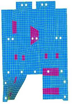
Since the minimum value of natural vibration frequency of the panel with base position of the brackets does not meet necessary requirements for frequencies and, therefore, the limiting values of linear displacements, it was decided to change the initial configuration of the panel by adjusting the location of the interface fixing points. Analysis of vibration modes of the panel (Fig. 4) by zones with maximum linear deviations allowed us to determine the places of correction of the interface points. By changing the location of the points for fixing the panel to the spacecraft body (Fig. 5), we managed to achieve an increase in the natural vibration frequency of the entire structure.
Table 5 shows the values of the parameters of the modal analysis of the panel with changed points of the location of the mounting brackets. The minimum natural vibration frequency of the modified instrument panel was 212.96 Hz.
а
Si»:-::!
■■1| ||ИИмМаВЦ MIM ■!'■!!■ '■■ ■■ W" "■■ ■■ Sue”l
SgH|g|iii™№iiMgi i
Tl! 0"'
Bgs%ffi »sasss BSSsSSiKKSiSI
в
б
iiii;i^:^
1-
lllм■■н■l»^”м■■M«S| ii™nim™8«ffl»gn!! 1ИМНН1Ы1НИМ*™
щ-дижеевенееее; иншдаик S!i!81l8^««S
H?№:
hs^ss::
Bi^^ „ gB
S Hi
■■■■Illi
SB ■■■■nullin'^
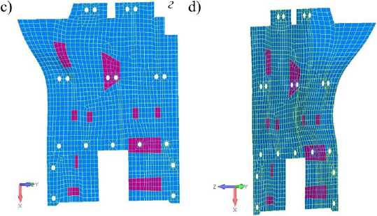
Рис. 4. Основные формы колебаний панели до модификации:
а – первая; б – вторая; в – третья; г – пятая
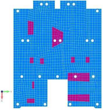
Рис. 5. Измененная конфигурация приборной панели
Fig. 4. Basic panel forms of oscillation before modification: а – first; b – second; c – third; d – fifth
Fig. 5. Modified dashboard configuration
Fig. 6 shows the first mode of vibration of a modified panel with changed interface points for mounting the brackets.
Table 5
Modal analysis results of the modified panel
|
Tone number |
Frequency, Hz |
Effective mass, % |
|||||
|
X |
Y |
Z |
RX |
RY |
RZ |
||
|
1 |
212.96 |
— |
— |
18.21 |
— |
7.43 |
— |
|
2 |
238.35 |
— |
— |
12.58 |
— |
9.62 |
— |
|
3 |
282.14 |
— |
— |
19.43 |
— |
11.19 |
— |
|
5 |
313.60 |
— |
— |
8.85 |
— |
6.08 |
— |
|
6 |
322.80 |
— |
— |
8.63 |
— |
3.73 |
— |
|
7 |
373.70 |
— |
— |
2.73 |
— |
1.23 |
— |
|
8 |
399.98 |
— |
— |
3.44 |
— |
1.68 |
— |
|
9 |
421.65 |
— |
— |
1.44 |
— |
— |
— |
|
10 |
448.78 |
7.73 |
17.01 |
— |
16.81 |
3.37 |
14.31 |
|
Total |
7.73 |
17.01 |
75.72 |
17.66 |
45.22 |
14.31 |
|
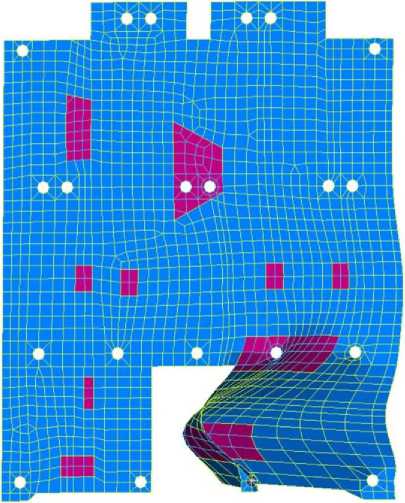
Рис. 6. Первая форма колебаний модифицированной панели
Fig. 6. The first form of oscillation of the modified panel
Calculation of the strength of a modified panel against quasi-static loading
Conducted quasi-static calculation of the instrument panel design (Tables 6, 7) confirms presence of required margin of safety for its safe operation, which is confirmed by stress distribution pattern (Fig. 7).
Table 6
Results of quasi-static calculation of finishing material after panel modification
|
Material |
σ |
η |
|
Aluminum plate |
65 |
5.44 |
Table 7
Results of quasi-static calculation of honeycomb filler after panel modification
|
Material |
τ yz |
τ xz |
η |
|
Aluminum plate |
0.05 |
0.16 |
6.65 |
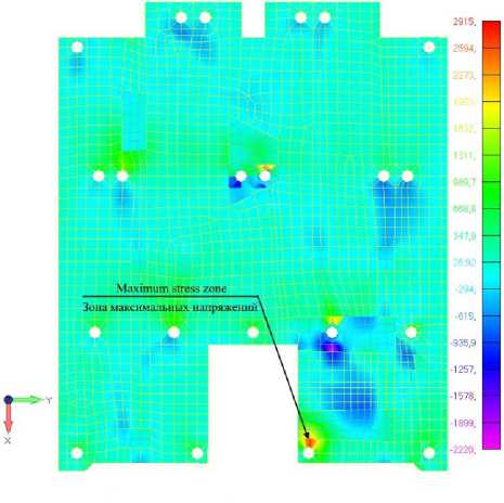
Рис. 7. Зона максимальных напряжений после модификации расположения креплений панели
Fig. 7. Maximum stress zone after modification of the panel mounting configuration
Conclusion
Our modal analysis made it possible to modify the spacecraft instrument panel and bring it in line with the requirements for natural vibration frequencies. With the help of rational redistribution of the interface points, it was possible to achieve an increase in the lower limit of natural vibration frequencies to 212, 96 Hz without increasing the mass of the structure. Quasi-static analysis confirmed the presence of a sufficient margin of safety for instrument panel and possibility of placing additional instruments on it by increasing the safety margin after changing locations of attach points of the panel to a spacecraft body. The proposed approach to modal analysis of structural elements can be used in engineering calculations for spacecraft design.
References Optimization the position of the spacecraft instrument panel mounting points based on modal analysis
- Daneev A. V., Rusanov M. V., Sizykh V. N. [Conceptual schemes of dynamics and computer modeling of spatial motion of large structures] Sovremennyye tekhnologii. Sistemnyy analiz. Modelirovaniye, 2016, No. 4, P. 17–25 (In Russ.).
- Kolga V. V., YarkovI. S., Yarkova E. A.Development of the heat panel of the small space apparatus for navigation support.Siberian journal of science and technology. 2020, Vol. 21, No. 3, 382–388. DOI: 10.31772/2587-6066-2020-21-3-382-388.
- Testoyedov N. A., Kolga V. V., Semenova L. A.Proyektirovaniye i konstruirovaniye bal-listicheskikh raket i raket nositeley [Design and construction of ballistic missiles and launch vehicles].Krasnoyarsk, 2014, 308 p.
- Zamyatin D. A., Kolga V. V. [Construction of anisogrid power structure of the spacecraft adapter] Мaterialy XХII Mezhdunar. nauch. konf. “Reshetnevskie chteniya” [Materials XХII Intern.Scientific.Conf “Reshetnevreading”].Krasnoyarsk, 2019, P. 26–28 (In Russ.).
- Vasiliev V. V., Barynin V. A., Rasin A. F., Petrokovskii S. A., Khalimanovich V. I.Anisogrid composite lattice structures – development and space applications.Composites and Nanostructures. 2009, Vol. 3, P. 38–50.
- Lopatin A. V., Morozov E. V., Shatov A. V.Axial deformability of the composite lattice cylindrical shell under compressive loading: Application to a load-carrying spacecraft tubular body.Composite Structures. 2016, Vol. 146, P. 201–206.
- Gaidachuk V. E., Kirichenko V. V., Kondratyev A. V. [Conceptual approach to the formation of physical and mechanical characteristics of sandwich structures of composite structures of rocket and space technology] Otkrytyye informatsionnyye i komp'yuternyye integrirovannyye tekhnologii. 2014, P. 27–36 (In Russ.).
- Rychkov S. P.Modelirovaniye konstruktsiy v srede Femap with NX Nastran [Modeling of structures in the Femap with NX Nastran environment]. Moscow, DMK Press Publ., 2013, 784 p.
- Shimkovich D. G. Femap & Nastran. Inzhenernyy analiz metodom konechnykh elemen-tov[Femap & Nastran. Engineering analysis by the finite element method]. Moscow, DMK Press Publ., 2012, 702 p.
- MSC Nastran.User’s guide: MSC. – Siemens Product Lifecycle Management Software Corporation; 2014. P. 886. Available at: https://docs.plm.automation.siemens.com/data_services/ resources/nxnastran/10/help/en_US/tdocExt/pdf/User.pdf.
- Timoshenko S. P. Kolebaniya v inzhenernom dele [Oscillations in engineering]. Moscow, NAUKA, 1957, 444 p. (In Russ.).
- Biderman V. L.Teoriya mekhanicheskikh kolebaniy[Theory of mechanical vibrations]. Moscow, Vysshaya shkola Publ., 1980, 408 p.
- Lopatin A. V., Morozov E. V.Fundamental frequency of an orthotropic rectangular plate with an internal centre point support.Composite Structures. 2011, Vol. 93, P. 2487–2495.
- Lopatin A. V., Morozov E. V.Fundamental frequency of an orthotropic rectangular plate with an internal centre point support.Composite Structures. 2011, Vol. 93, P. 2487–2495.
- Malmeyster A. K., Tamuzh V. P., Teters G. A.Soprotivleniye polimernykh i kompozitnykh materialov[Resistance of polymer and composite materials]. Riga, Zinatne Publ., 1980, 572 p.
